


 Stratos® 100
Operating Instructions |
Istruzioni d’uso |
Page 3 |
Pagina 57 |
Bedienungsanleitung |
Instrucciones de uso |
Seite 21 |
Pagina 75 |
Mode d’emploi |
|
Page 39 |
|

2

Stratos® 100
|
|
|
Page |
Views of the Unit and Parts List |
4 |
||
– |
Description of components |
4 |
|
– |
Accessories |
6 |
|
– Accessories for average model transfer |
7 |
||
– Accessories for personalized model transfer |
7 |
||
1 |
|
Introduction / Signs and Symbols |
8 |
1.1 |
|
Preface |
8 |
1.2 |
|
Signs and symbols |
8 |
1.3 |
|
Information on the Operating Instructions |
8 |
2 |
|
Safety First |
9 |
2.1 |
|
Field of application |
9 |
2.2 |
|
Health and safety instructions |
9 |
3 |
|
Product Description |
9 |
3.1 |
|
Functional description |
9 |
3.2 |
|
Indication, contraindication |
9 |
4 |
|
Installation and Initial Start-up |
10 |
4.1 |
|
Unpacking and checking the contents |
10 |
4.2 |
|
Assembly and initial set-up |
10 |
5 |
|
Handling and Operation |
10 |
5.1 |
|
Centric position |
10 |
5.2 |
|
Lateral and Bennett movement |
11 |
5.3 |
|
Protrusion |
11 |
5.4 |
|
Retrusion |
12 |
6 |
|
Model Orientation in the Stratos 100 |
13 |
6.1 |
|
Average orientation of dentulous and edentulous cases with a rubber band |
13 |
6.2 |
|
Average orientation of dentulous cases with the set-up table |
13 |
6.3 |
|
Average orientation of edentulous cases with the horizontal guide |
14 |
6.4 |
|
Average orientation of dentulous cases with the horizontal guide |
14 |
6.5 |
|
Personalized model transfer with the registration joint holder |
15 |
6.6 |
|
Personalized model transfer with the UTS transferbow |
16 |
6.7 |
|
Personalized setup of anterior guidance |
16 |
7 |
|
Maintenance and Cleaning |
17 |
7.1 |
|
Monitoring and maintenance |
17 |
7.2 |
|
Cleaning |
17 |
8 |
|
What If ... |
18 |
8.1 |
|
Technical malfunctions |
18 |
8.2 |
|
Repairs |
18 |
9 |
|
Product Specifications |
19 |
9.1 |
|
Delivery form |
19 |
9.2 |
|
Technical data |
19 |
10 |
Miscellaneous |
20 |
|
10.1 |
Tips on the coordination of articulators |
20 |
|
english
3

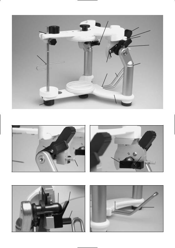
Parts List
Stratos® 100
1.1Incisal plate
1.2Incisal guide rod
1.3Incisal indicator
1.4Guide rod holder
1.5Guide rod retaining screw
1.6Guide rod initial set position (red)
1.7FI knurled screw
1.8Hole for incisal indicator
2.1GI knurled screw
2.2Lower frame
2.3Upper frame
2.4Incline supports
2.5Notch for rubber band
2.6Non-slip base
2.7Joint bolt
3.1Bennett inserts
3.2B knurled screw
4.1Centric fixation lock (activable centric locking system)
4.2Centric rubber band
4.3Centric rubber band holder
5.0Protrusion insert (fix)
6.0Locating hole for transferbow
7.1Holding device for incline support holder
7.2Incline support holder
8.0Articulator number
9.0Opening stop
10.0 Protrusion screw with spring
33 Retentive base block
4

|
|
|
|
|
|
|
|
|
|
|
|
8.0 |
2.1 |
3.1 |
|
|
|
|
|
|
|
|
||||||||
1.7 |
|
|
|
2.3 |
|
|
|
|
|
3.2 |
|
|
|
4.1 |
||||||||||||||||
|
|
|
|
|
|
|
|
|
|
|
|
|
|
|
|
|
|
|
|
|
|
|
|
|||||||
|
|
|
|
|
|
|
|
|
|
|
|
|
|
|
|
|
|
|
|
|
|
|
|
|
|
|||||
1.6 |
|
|
|
|
|
|
|
|
|
|
|
|
|
|
|
|
|
|
|
|
|
9.0 |
||||||||
|
|
|
|
|
|
|
|
|
|
|
|
|
|
|
|
|
|
|
|
|
4.2 |
|||||||||
1.4 |
|
|
|
|
|
|
|
|
|
|
|
|
|
|
|
|
|
|
|
|
|
|
|
|
||||||
|
|
|
|
|
|
|
|
|
|
|
|
|
|
|
|
|
|
|
|
|
|
|
|
|||||||
1.5 |
|
|
|
|
|
|
|
|
|
|
|
|
|
|
|
|
|
|
4.3 |
|||||||||||
|
|
|
|
|
|
|
|
|
|
|
|
|
|
|
|
|
|
|||||||||||||
|
|
|
|
|
|
|
|
|
|
|
|
|
|
|
33 |
|
|
|
|
|
|
|
|
|||||||
|
|
|
|
|
|
|
|
|
|
|
|
|
|
|
|
|
|
|
|
|
|
|
|
|
|
|
|
|||
1.8 |
|
|
|
|
|
|
|
|
|
|
|
|
|
|
|
|
|
|
|
|
|
|
|
|
10.0 |
|||||
|
|
|
|
|
|
|
|
|
|
|
|
|
|
|
|
|
|
|
|
|
|
|
|
|||||||
|
|
|
|
|
|
|
|
|
|
|
|
|
|
|
|
|
|
|
|
|
|
|
6.0 |
|||||||
|
|
|
|
|
|
|
|
|
|
|
|
|
|
|
|
|
|
|
|
|
|
|
||||||||
|
|
|
|
|
|
|
|
|
|
|
|
|
|
|
|
|
|
|
|
|
5.0 |
|
|
|
2.5 |
|||||
|
|
|
|
|
|
|
|
|
|
|
|
|
|
|
|
|
|
|
|
|
|
|
|
|
|
|
|
|
||
1.3 |
|
|
|
|
|
|
|
|
|
|
|
|
|
|
33 |
|
|
7.1 |
7.2 |
|
|
|
|
|
|
|
||||
|
|
|
|
|
|
|
|
|
|
|
|
|
|
|
|
|
|
|
|
|
|
|
||||||||
|
|
|
|
|
|
|
|
|
|
|
|
|
|
|
|
|
|
|
|
|
|
|
|
|||||||
1.2 |
|
|
|
|
|
|
|
|
|
|
|
|
|
|
|
|
|
|
|
|
|
|
|
|||||||
|
|
|
|
|
|
|
|
8.0 |
|
|
|
|
|
|
|
|
|
|
|
|
|
|
|
|
2.4 |
|||||
|
|
|
|
|
|
|
|
|
|
|
|
|
|
|
|
|
|
|
|
|
|
|
|
|
|
|
|
|||
|
|
|
|
|
|
|
|
|
|
|
|
|
|
|
|
|
|
|
|
|
|
|
|
|
|
|
||||
|
|
|
|
|
|
|
|
|
|
|
|
|
|
|
|
|
|
|
|
|
|
|
|
|
|
|
|
|
||
1.1 |
|
|
|
|
|
|
|
|
|
|
|
|
|
|
|
|
|
|
|
|
|
|
|
|
|
|
|
|
||
|
|
|
|
|
|
|
|
|
|
|
|
|
|
|
|
|
|
|
|
|
|
|
|
|
|
|
|
|||
|
|
|
|
|
|
|
|
|
|
|
|
|
|
|
|
|
|
|
|
|
|
|
|
|
|
|
|
|
|
|
|
|
|
|
|
|
|
|
|
|
|
|
|
|
|
|
|
|
|
|
|
|
|
|
|
|
|
|
|
|
|
|
|
|
|
|
|
|
|
|
|
|
|
|
|
|
2.1 |
|
|
|
|
|
|
|
|
|
|
|||||
1.7 |
|
|
|
|
|
|
|
|
|
|
|
|
|
|
|
|
|
2.2 |
|
|
2.6 |
|||||||||
|
|
|
|
|
|
|
|
|
|
|
|
|
|
|
|
|
|
|
|
|
|
|
|
|||||||
|
|
|
|
|
|
|
|
|
|
|
|
|
|
|
|
|
|
|
|
|
|
|
|
|
|
|
|
|
|
|
4.1 
4.3
3.1 |
3.2 |
|
10.0
2.73.1
7.1
7.2
3.2
5

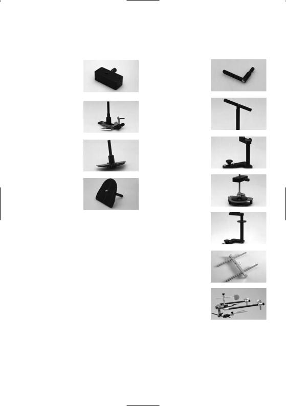
Accessories for the Stratos® 100
3015° incisal plate made of plastic
3130° incisal plate made of plastic
32Incisal plate made of MMA-soluble material for personalized anterior guidance
32
31
30
33 |
Retentive base block |
|
|
34 |
Plaster protection plate |
36 |
|
35 |
Magnetic base block |
||
|
|||
36 |
Collar |
37 |
|
37 |
Retention disk |
||
|
33 34
35
6
Accessories for |
|
Accessories for |
|
||||
average model transfer |
|
personalized model transfer |
|
||||
40 |
Instrument carrier for |
|
50 |
Plane indicator |
|
|
|
40 |
|
|
|||||
|
horizontal guide, set-up |
|
|
|
50 |
||
|
|
|
|
|
|||
|
table, 2-D setting up |
|
|
|
|
||
|
|
|
|
|
|
||
|
template and bite fork |
|
|
|
|
|
|
|
support |
|
|
|
|
|
|
|
|
|
|
|
|
|
|
|
|
|
|
|
|
|
|
41 |
Horizontal guide |
|
|
51 |
Bite fork support |
|
|
|
|
|
|
||||
|
|
|
|
|
|
||
41.1 Symphysis fork |
|
41 |
|
|
|
51 |
|
|
|
|
41.1 |
|
|
|
|
|
|
|
|
|
|
|
|
|
|
|
|
|
|
|
|
|
|
|
|
|
|
|
|
42 2-D setting up template |
|
|
52 |
Registration joint holder |
|
|
|
|
|
|
|||||
|
|
|
(CP) |
|
52 |
||
|
|
|
42 |
|
|
||
|
|
|
|
|
|
|
|
|
|
|
|
|
|
|
|
|
|
|
|
|
|
|
|
|
|
|
|
|
|
||
43 Set-up table |
|
53 3-D setting up template |
|
|
|||
43 |
|
||||||
|
|
|
|
||||
|
|
|
|
|
|
53 |
|
|
|
|
|
|
|
|
|
|
|
|
|
|
|
|
|
|
|
|
|
|
|
|
|
|
|
|
|
|
|
||
|
|
|
54 |
FH registration joint |
|
|
|
|
|
|
|
|
holder |
|
54 |
|
|
|
|
|
|
|
|
|
|
|
60 |
Adjustable support pins |
|
|
|
|
|
|
|
|
|||
|
|
|
|
60 |
|||
|
|
|
|
|
(Type 2) for the UTS |
|
|
|
|
|
|
|
|
|
|
|
|
|
|
|
transferbow |
|
|
|
|
|
|
|
|
|
|
|
|
|
|
|
|
||
|
|
|
61 |
UTS transferbow system |
|
61 |
|
|
|
|
|
|
|
|
|
7

1. Introduction / Signs and Symbols
1.1Preface
Dear Customer
Thank you for having purchased the Stratos 100 articulator. The Stratos 100 is an advanced technology product that is characterized by high quality and precision.
The Stratos 100 has been designed according to the latest industry standards. Inappropriate use may be hazardous. Please observe the relevant safety instructions and do read the Operating Instructions carefully.
1.2Signs and symbols
The signs and symbols in these Operating Instructions facilitate the finding of important information. They have the following meanings:
Risks and dangers
Important information
We wish you much success and satisfaction with the Stratos 100. |
Contraindication |
|
1.3 Information on the Operating Instructions
Target group: dentists, dental technicians, dental lab professionals
These Operating Instructions facilitate the correct, safe and economic use of the Stratos 100 articulator.
If you have lost the Operating Instructions, you may order an extra copy at a nominal fee from your local Ivoclar Vivadent Service Center.
8
2. Safety First
This chapter is particularly important for staff who work with the apparatus or who have to carry out maintenance or repair work.
2.1Field of application
The Stratos 100 must only be used for the indications stipulated in Chapter 3. Further instructions to assure the proper use of the Stratos 100 articulator are as follows:
–The instructions, regulations and notes in these Operating Instructions must be observed.
–The unit must be properly maintained (see Chapter 7).
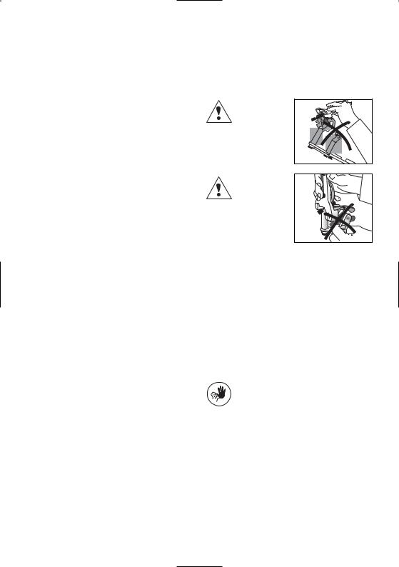
2.2Health and safety instructions
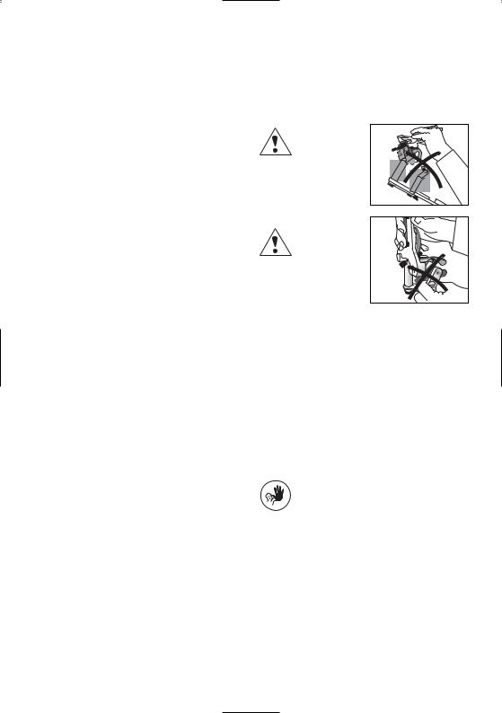
If the centric rubber bands are removed from their retainers and the centric fixation
lock is open, the upper and lower frames may be accidentally separated.
Risk of crushing between centric locking catch and incline support.
3. Product Description
3.1Functional description
The Stratos 100 is an average-value articulator built according to the Camper's plane (CP). It is fully coordinated with the Ivoclar Vivadent Biofunctional Prosthetic System (BPS). Consequently, the articulator facilitates the easy and effective application of a prosthetic system that has been successful for many years.
The device is equipped with a fix protrusion path angle of 30°. The Bennett angle is 15° and 30°.
Furthermore, a retrusive movement of 35° as well as an “immediate side shift” are integrated in the Stratos 100.
A newly developed activable centric locking system permits the articulator to be set to a precise, reproducible initial set position and facilitates separation and connection of the upper and lower frames. Even when the centric lock is open, the upper and lower frames are still connected. Only after removing the centric rubber bands from their retainers can the two parts be separated.
The locating holes for transferbows, automatic centric return and a non-slip base are all standard equipment. In addition, the Stratos 100 features a dirt-and-wear-resistant finish.
A wide range of accessories permits the Stratos 100 to meet the specific needs and requirements of every user.
3.2Indication and contraindication
Indication
The articulator is suitable for the spatial fixation of models for lab-fabricated reconstructions. The basic equipment permits simulation of average movement patterns of the human temporomandibular joint.
Contraindication
No contraindications are known to date provided that the articulator is used strictly according to the Operating Instructions.
9

4. Installation and Initial Start-up |
5. Handling and Operation |
4.1Unpacking and checking the contents
Remove the components of the Stratos 100 from their packaging and check the delivery for completeness.
Stratos 100 basic model:
1 x Stratos 100
1 x Incisal plate 0°
1 x Incisal indicator
2 x Retentive base blocks
1 x Plaster protection plate
1 x Incline support holder
If certain parts are missing or damaged, contact your local Ivoclar Vivadent Customer Service. We recommend keeping the original packaging for possible future transportation purposes.
4.2Assembly and initial set-up
Incline support holder
The incline support holder enables ergonomic handling of the articulator. If mounted, it maintains the articulator at approx. a 45° angle. This position permits a superb overview of the model mounted in the articulator.
7.1
7.2
Insert the incline support holder (7.2) into the holding device (7.1) for the incline support holder. If necessary, the incline support holder can be removed from the apparatus.
Secure the base block (33) to the articulator by means of the GI knurled screw (2.1).
Alternatively, the protrusion screw (5.2) including spring may be mounted.
5.1Centric position
The Stratos 100 features a precise centric locking system that can be activated in the following positions:
5.1.1 Centric fixation (4.1) open
This position permits the simulation of jaw movements.
5.1.2 Centric fixation lock (4.1) closed
In this position, the two frames of the Stratos 100 can no longer be separated and the articulator is fixed in the centric position. The centric fixation can be opened by applying slight pressure. This greatly facilitates handling for the user.
Loosen the centric fixation before carrying out masticatory movements.
4.1
10
If the centric rubber bands (4.2) are removed, the two frames can be separated.
4.3
4.2
5.2Lateral and Bennett movement
5.2.1 Lateral and Bennett movement
The lateral movements can be simulated when the centric fixation (4.1) is open, according to the schematic below.
To perform this movement, press with your thumb unilaterally on the joint of the corresponding side.
By loosening the B knurled screw (3.2) the Bennett insert (3.1) can be removed.
5.3Protrusion
5.3.1 Protrusive movements can be simulated if the centric fixation (4.1) is open, according to the schematic below.
To effect this movement, press with your thumb bilaterally on the joint of the corresponding side.
3.1
3.2
11

5.3.2 Protrusion screw (10.0) for centric shift
The protrusion screw permits each condyle to be incrementally advanced into a protrusive position.
10.0
Important:
In this case, the centric fixation cannot be used.
5.4Retrusion
To simulate retrusive movements, the centric fixation lock (4.1) must be open and the Bennett inserts (3.1) removed.
This allows retrusive movements to be carried out properly.
12

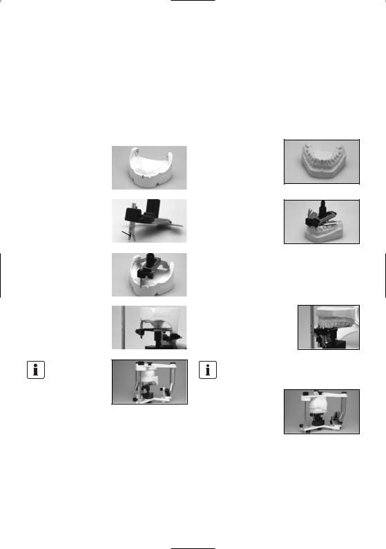
6. Model Orientation in the Stratos 100
6.1Average model orientation of dentulous and edentulous cases with a rubber band
6.1.1 Return articulator to the initial set position
–Check if Bennett inserts (3.1) are secured in place.
–Mount centric rubber bands (4.2).
–Bring centric fixation lock (4.1) into the upper position and secure in place.
–Secure incisal guide rod (1.2) in the initial position (red
mark 1.6) in the guide rod |
1.2 |
|
holder |
||
|
||
|
1.6 |
6.1.2 |
Incisal indicator (1.3) |
|
|
|
Slide the incisal indicator |
1.8 |
1.3 |
||
completely into the incisal guide |
|
|
|
|
rod (1.2). |
|
|
|
|
|
Insert the longer part of |
|
|
|
|
the incisal indicator |
|
|
|
|
(1.3) into the upper hole |
|
|
|
|
|
|
|
|
|
(1.8) of the incisal guide rod (note notch in the rod). |
|||
6.1.3 |
Next, attach the thin rub- |
|
|
|
|
|
|
||
ber band to the incline supports |
1.3 |
|
2.5 |
|
(2.4), notches (2.5), and under the |
|
|
||
longer part of the incisal indicator |
|
|
2.4 |
|
(1.3). |
|
|
|
|
6.1.4 |
Adjust occlusal plane |
|
|
|
|
|
|
||
1.3 |
|
|||
according to the rubber band. |
|
|
|
|
Adjust mesial contact area either |
|
|
|
|
between the mandibular central |
|
|
|
|
incisors or on the wax bite block, |
|
|
|
|
according to the tip of the incisal |
|
|
|
|
|
|
|
||
indicator (1.3). |
|
|
|
|
Example: edentulous case |
|
|
|
|
6.1.5 |
For best results, mount |
|
|
|
|
|
|
||
mandibular model on modelling |
|
|
|
|
material and adjust. After that, |
|
|
|
|
cast maxillary model. |
|
|
|
|
Example: dentulous case |
|
|
|
|
|
|
|
|
|
6.2Average orientation of dentulous cases with the set-up table
6.2.1 Return the articulator to the initial set position
– See 6.1.1 for description
Remove the incisal indicator (1.3).
6.2.2Mount instrument carrier to the upper frame (2.3) and fasten it with the GI knurled screw (2.1).
6.2.3Insert set-up table completely into the instrument carrier and secure it.
6.2.4Place articulator with the upper frame (2.3) facing down on the table. Orientate the dentulous mandibular model according to the mesial contact area and symmetry in the molar region. If necessary, use modelling material to hold it in place.
6.2.5Apply plaster on model and base block and close articulator slowly.
6.2.6Then, orientate maxillary model in the usual manner.
13
6.3Average orientation of edentulous cases with the horizontal guide
6.3.1 Return articulator to the initial set position
– See 6.1.1 for description
Remove incisal indicator (1.3). |
|
||
6.3.2 Mark and bisect the |
|
||
|
|||
Trigonom retromolare on the |
|
||
mandibular model. |
|
||
Bisect the distance between the |
|
||
|
|||
|
|||
upper and lower mucolabial folds |
|
||
and set the symphysis fork (4.1) |
|
||
of the horizontal plane on the |
4.1 |
||
resulting value. |
|||
|
|||
Using the resulting values, |
|
|
|
|
|
||
|
|
||
orientate the mandibular model |
|
|
|
to the horizontal guide and hold |
|
|
|
it in place, e.g. with a rubber |
|
|
|
band. |
|
|
|
6.3.3 Mount instrument carrier |
|
|
|
|
|
||
|
|
||
to the upper frame (2.3) |
|
|
|
Fasten horizontal guide in place |
|
|
|
by means of the knurled screw of |
|
|
|
the instrument carrier. |
|
|
|
Insert horizontal guide completely into the instrument carrier. After that, apply some plaster on the model and base block and close articulator slowly.
6.3.4 Next, orientate maxillary model as usual.
6.4Average orientation of dentulous cases with the horizontal guide
6.4.1 Return articulator to the initial set position
– See 6.1.1 for description
Remove incisal indicator (1.3).
6.4.2 Transfer maxillary mesial contact area vertically to the mandibular model. Mark the tips of both distobuccal cusps of the lower second molars. If these molars are missing, the first molars may be used instead.
–Put mandibular mesial contact area behind the incisal tip of the symphysis fork.
–Adjust horizontal guide in such a way that the rear edges barely cover the mar-
ked cusps of the second molars and align symmetry.
–The retromolar pads are used as reference points for free-end surfaces, similarly to the Trigonum retromolare in edentulous cases.
Subsequently, attach horizontal guide to the model with e.g. wax or a rubber band.
6.4.3Mount instrument carrier to the upper frame (2.3).
Fasten horizontal guide in place by means of the knurled screw of the instrument carrier.
Insert horizontal guide completely into the instrument carrier.
After that, apply some plaster on the model and base block and close articulator slowly.
6.4.4 Next, orientate maxillary model as usual.
14

6.5Personalized model transfer with the registration joint holder
6.5.1 Return articulator to the initial set position
– See 6.1.1 for description
Remove incisal indicator (1.2).
6.5.2Mount the plane indicator (50) instead of the incisal guide rod (1.2).
6.5.3Mount bite fork support (51) to the lower frame (2.2) by means of the instrument carrier (40).
6.5.4Insert registration joint holder (52) instead of the incisal
plate (1.1) and secure it. |
52 |
|
6.5.5 6.5.5 Mount UTS registration to the registration joint holder and secure bite fork with the bite fork support.
Example: Centric Tray
Example: UTS bite fork (dentulous case)
6.5.6 Mount maxillary model to the bite fork and cast. Close articulator until the plane indicator lies on the registration joint holder.
Example: UTS bite fork (edentulous case)
FH registration joint holder |
|
|
(54) |
|
|
The procedure is the same as with |
50 |
|
the CP registration joint holder. |
||
|
||
The plane indicator (50) lies on |
54 |
|
the relevant support of the FH |
||
registration joint holder (54). |
|
6.5.7 Subsequently, orientate mandibular model in the usual manner.
15
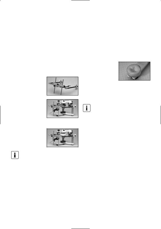
6.6Personalized model transfer with the UTS transferbow
6.6.1 Return articulator to the initial set position.
– See 6.1.1 for description
Remove incisal guide rod (1.2).
6.6.2Mount the plane indicator (50) instead of the incisal guide rod (1.2).
6.6.3Mount bite fork support to the lower frame (2.2) by means of the instrument carrier.
6.6.4
–Remove nose rest from the transferbow and insert support pins (Type II) (60) from above.
–Insert the UTS into the locating holes for transferbows (6.1).
–Using the support pins, adjust the transferbow so that it is parallel to the table top.
–Finally, secure bite fork with the bite fork support.
6.6.5 Mount maxillary model to the bite fork and cast. Close the articulator until the plane indicator rests in the notch in the cross-beam of the support pin.
If Type-I support pins are used, close articulator until the plane indicator touches the SME indicator of the transferbow.
6.6.6 Then, orientate mandibular model in the usual manner.
6.7Personalized setup of anterior guidance
For the fabrication of personalized incisal plates, Ivoclar Vivadent offers a special transparent incisal plate. The plate is made of a MMA-soluble plastic that bonds with the set-up resin (SR Ivolen). Anterior guidance plates thus fabricated can always be exactly repositioned in the Stratos 100.
Procedure
First, mount the transparent 0° incisal plate. Then, position the models of the patient for which the anterior guidance should be formed in the Stratos 100. Subsequently, mix appropriate resin and spread it on the incisal plate.
Finally, simulate the registered masticatory movements (protrusion, retrusion, laterotrusion) with the upper frame of the Stratos 100. The movement patterns will thus be scratched
into the resin by the incisal guide rod and recorded after polymerization of the resin.
The forming of the natural facets should be done from excursion to centric. Otherwise, the resin might be forced out of the incisal plate. Make sure that no vertical increase of occlusion occurs.
16

7. Maintenance and Cleaning
This chapter describes the user maintenance and cleaning procedure for the Stratos 100. Only those tasks that can be carried out by qualified dental lab experts are listed. All other tasks must be performed by qualified service personnel at a certified Ivoclar Vivadent Service Center.
7.1Monitoring and maintenance
The time for these maintenance procedures depends on the frequency of use and the working habits of the user. For these reasons, the recommended times are only approximates.
What |
Part |
Frequency |
Check centric rubber band for damage and |
Centric rubber band |
Monthly or as necessary |
cracks and replace, if necessary. |
|
|
Check if knurled screws are dirty. |
Knurled screw |
Weekly |
|
|
|
Check if joint bolt is sufficiently lubricated. |
Joint bolt |
Monthly or as necessary |
|
|
|
Check if incline support holder and holding |
Holding device for incline support holder |
Weekly or as necessary |
device are dirty. |
|
|
|
|
|
7.2. Cleaning
What |
Frequency |
Cleaning agent/Measure |
Knurled screws contaminated with wax or |
Weekly or as necessary |
Rinse with warm water |
plaster |
|
|
|
|
|
Joint bolt contaminated with dust |
Weekly or as necessary |
Rinse with warm water |
|
|
|
Protect the Stratos 100 from acids and solvents (e.g. MMA) to prevent the finish from being damaged.
17

8. What If ...?
This chapter will help you to recognize malfunctions and take appropriate measures or, if possible, to perform some repairs.
8.1 Technical malfunctions
Error |
Cause/Description |
Action |
|
|
|
Upper frame exceeds opening stop and |
The opening stop is not in place or |
Replace opening stop or mount it properly. |
slips backwards. |
defective. |
|
Articulator cannot be opened when the |
Centric fixation has been fixed too tightly. |
Fix centric fixation less tightly. |
centric fixation lock is closed. |
|
|
|
|
|
Joint bolt is damaged or grooved. |
The articulator was forcibly opened and |
Loosen centric fixation lock before opening |
|
closed without the centric fixation being |
and closing the articulator. |
|
loosened. |
|
The surface of the articulator is damaged or etched.
Surface was cleaned with acid, solvent or lye.
Do not use acid, solvents or lye to clean the apparatus.
The surface of the apparatus is scratched or damaged.
Surface was scratched with a sharp instrument.
Do not scratch the surface with a sharp instrument.
8.2Repairs
Repairs may only be carried out by a certified Ivoclar Vivadent Service Center. Please refer to the addresses mentioned in Chapter 10. If repairs during the warranty period are not carried out by a certified Ivoclar Vivadent Service Center, the warranty will expire immediately.
18

9. Product Specifications
9.1 |
Delivery forms |
9.2 |
Technical data |
|
Stratos 100 basic model |
– |
Bonnwill triangle 108 mm |
||
1 |
Stratos 100 |
– |
Balkwill angle 15° |
|
1 |
Incisal plate 0° |
– |
Working height 118 mm |
|
1 |
Incisal indicator |
– |
Retrusion path angle 35° |
|
2 |
Retentive base blocks |
– |
Protrusion angle: 30° |
|
1 |
Plaster protection plate |
– |
Bennett angle 30°/15° |
|
1 |
Incline support holder |
– |
Exchangeable, colour-coded 0° incisal plate. Other angles are |
|
2 |
Protrusion screws with spring |
|
available as accessories. |
|
"Average” Accessories Assortment |
– |
Weight: 950 g |
||
– Colour: white (RAL 9016), incline support: silver |
||||
|
|
|||
–1 Instrument carrier
–1 Setup table
–1 Horizontal guide
–1 2-D setting up template
“Personalized” Accessories Assortment
–1 Incisal plate 15° and 30° each, as well as 1 personalized plate
–1 Instrument carrier
–1 Plane indicator
–1 CE registration joint holder
–1 Bite fork support
Separately available:
–Incisal plate 15° or 30°
-Incisal plate for personalized anterior guidance, package of 5 plates
–Instrument carrier
–Plane indicator
–Horizontal guide
–2-D setting up template
–3-D setting up template
–Set-up table
–Adjustable support pins (Type II)
–CE registration joint holder
–Bite fork support
–Magnetic base blocks, package of 2 or 10 blocks
–Retentive base blocks, package of 10 or 50 blocks
–Plaster protection plate, package of 5 plates
–FH registration joint holder
–Incline support holder
–Retention disk for magnetic base block
Colour code (incisal plate)
All exchangeable parts with an angle indication are colour-coded:
– |
white |
0° |
– |
red |
15° |
– |
black |
30° |
–transparent for personalized anterior guidance
The delivery forms may vary from country to country.
19

10. Miscellaneous
10.1 Tips on the coordination of articulators
The companies below offer split-cast systems for the Stratos 100.
These systems permit users to coordinate their Stratos 100 articulators. For further information please contact:
Adesso-split
Baumann Dental GmbH
Frankenstr. 25
D-75210 Keltern-Ellmendingen
Quicksplit
Hans Rossner & Sohn GmbH
Dentaltechnik
Ulmerstrasse 11
D-87700 Memmingen
Please note that the standard accessories can no longer be used after the apparatus have been coordinated.
This apparatus has been developed for use in dentistry. Setup and operation should be carried out strictly according to the Operating Instructions. Liability cannot be accepted for damages resulting from misuse or failure to observe the Instructions. The user is solely responsible for testing the apparatus for its suitability for any purpose not explicitly stated in the Instructions. Descriptions and data constitute no warranty of attributes and are not binding.
20
Stratos® 100
|
|
|
Seite |
Geräteübersicht, Teileverzeichnis |
22 |
||
– |
Bezeichnung der Teile |
22 |
|
– |
Zubehör |
24 |
|
– Zubehör für die mittelwertige Modellübertragung |
25 |
||
– Zubehör für die individuelle Modellübertragung |
25 |
||
1 |
|
Einleitung und Zeichenerklärung |
26 |
1.1 |
|
Vorwort |
26 |
1.2 |
|
Zeichenerklärung |
26 |
1.3 |
|
Angaben zur Bedienungsanleitung |
26 |
2 |
|
Sicherheit geht vor |
27 |
2.1 |
|
Bestimmungsgemässe Verwendung |
27 |
2.2 |
|
Sicherheitsund Gefahrenhinweise |
27 |
3 |
|
Produktbeschreibung |
27 |
3.1 |
|
Aufbau des Gerätes, Funktionsbeschreibung |
27 |
3.2 |
|
Indikation, Kontraindikation |
27 |
4 |
|
Installation und erste Inbetriebnahme |
28 |
4.1 |
|
Auspacken und Lieferumfang prüfen |
28 |
4.2 |
|
Zusammenbau und erste Inbetriebnahme |
28 |
5 |
|
Handhabung, Bedienung |
28 |
5.1 |
|
Zentrikposition |
28 |
5.2 |
|
Lateralund Bennettbewegung |
29 |
5.3 |
|
Protrusionsbewegung |
29 |
5.4 |
|
Retrusionsbewegung |
30 |
6 |
|
Praktische Anwendung der Modellorientierung |
31 |
6.1 |
|
Bezahnter oder unbezahnter Fall mit Gummiband (mittelwertig) |
31 |
6.2 |
|
Bezahnter Fall mit dem Einrichttisch (mittelwertig) |
31 |
6.3 |
|
Unbezahnter Fall mit Fundamentwaage (mittelwertig) |
32 |
6.4 |
|
Bezahnter Fall mit Fundamentwaage (mittelwertig) |
32 |
6.5 |
|
Modellübertragung mit dem Registriergelenkträger (individuell) |
33 |
6.6 |
|
Modellübertragung mit dem UTS-Transferbogen (individuell) |
34 |
6.7 |
|
Individuell aufgebauter Frontzahnführungsteller |
34 |
7 |
|
Unterhalt, Reinigung, Diagnose |
35 |
7.1 |
|
Kontrollund Unterhaltsarbeiten |
35 |
7.2 |
|
Reinigungsarbeiten |
35 |
8 |
|
Was ist, wenn ... |
36 |
8.1 |
|
Technische Störungen |
36 |
8.2 |
|
Reparaturarbeiten |
36 |
9 |
|
Produktspezifikationen |
37 |
9.1 |
|
Lieferform |
37 |
9.2 |
|
Technische Daten |
37 |
10 |
Sonstiges |
38 |
|
10.1 |
Tipps zur Artikulator-Gleichschaltung |
38 |
|
deutsch
21

Teileverzeichnis
Stratos® 100
1.1Inzisalteller
1.2Inzisalstift
1.3Inzisalpunktzeiger
1.4Inzisalstifthalter
1.5Inzisalstift-Rändelschraube
1.6Inzisalstift Nullposition (rot)
1.7FI-Rändelschraube
1.8Bohrung für Inszialpunktzeiger
2.1GI-Rändelschraube
2.2UK-Grundteil
2.3OK-Grundteil
2.4Säulen
2.5Kerbe für Gummiband
2.6Gummifüsse
2.7Gelenkbolzen
3.1Bennett-Einsätze
3.2B-Rändelschraube
4.1Zentrikfixierung (aktivierbarer Schnellverschluss)
4.2Zentrikgummi
4.3Halterung für Zentrikgummi
5.0Protrusions-Einsatz (fix)
6.0Transferbogenanschluss
7.1Halterung für Stützfuss
7.2Stützfuss
8.0Gerätenummer
9.0Öffnungsanschlag
10.0Protrusionsschraube mit Feder 33 Sockelplatte retentiv
22
|
|
|
|
|
|
|
|
|
|
|
|
8.0 |
2.1 |
3.1 |
|
|
|
|
|
|
|
|
||||||||
1.7 |
|
|
|
2.3 |
|
|
|
|
|
3.2 |
|
|
|
4.1 |
||||||||||||||||
|
|
|
|
|
|
|
|
|
|
|
|
|
|
|
|
|
|
|
|
|
|
|
|
|||||||
|
|
|
|
|
|
|
|
|
|
|
|
|
|
|
|
|
|
|
|
|
|
|
|
|
|
|||||
1.6 |
|
|
|
|
|
|
|
|
|
|
|
|
|
|
|
|
|
|
|
|
|
9.0 |
||||||||
|
|
|
|
|
|
|
|
|
|
|
|
|
|
|
|
|
|
|
|
|
4.2 |
|||||||||
1.4 |
|
|
|
|
|
|
|
|
|
|
|
|
|
|
|
|
|
|
|
|
|
|
|
|
||||||
|
|
|
|
|
|
|
|
|
|
|
|
|
|
|
|
|
|
|
|
|
|
|
|
|||||||
1.5 |
|
|
|
|
|
|
|
|
|
|
|
|
|
|
|
|
|
|
4.3 |
|||||||||||
|
|
|
|
|
|
|
|
|
|
|
|
|
|
|
|
|
|
|||||||||||||
|
|
|
|
|
|
|
|
|
|
|
|
|
|
|
33 |
|
|
|
|
|
|
|
|
|||||||
|
|
|
|
|
|
|
|
|
|
|
|
|
|
|
|
|
|
|
|
|
|
|
|
|
|
|
|
|||
1.8 |
|
|
|
|
|
|
|
|
|
|
|
|
|
|
|
|
|
|
|
|
|
|
|
|
10.0 |
|||||
|
|
|
|
|
|
|
|
|
|
|
|
|
|
|
|
|
|
|
|
|
|
|
|
|||||||
|
|
|
|
|
|
|
|
|
|
|
|
|
|
|
|
|
|
|
|
|
|
|
6.0 |
|||||||
|
|
|
|
|
|
|
|
|
|
|
|
|
|
|
|
|
|
|
|
|
|
|
||||||||
|
|
|
|
|
|
|
|
|
|
|
|
|
|
|
|
|
|
|
|
|
5.0 |
|
|
|
2.5 |
|||||
|
|
|
|
|
|
|
|
|
|
|
|
|
|
|
|
|
|
|
|
|
|
|
|
|
|
|
|
|
||
1.3 |
|
|
|
|
|
|
|
|
|
|
|
|
|
|
33 |
|
|
7.1 |
7.2 |
|
|
|
|
|
|
|
||||
|
|
|
|
|
|
|
|
|
|
|
|
|
|
|
|
|
|
|
|
|
|
|
||||||||
|
|
|
|
|
|
|
|
|
|
|
|
|
|
|
|
|
|
|
|
|
|
|
|
|||||||
1.2 |
|
|
|
|
|
|
|
|
|
|
|
|
|
|
|
|
|
|
|
|
|
|
|
|||||||
|
|
|
|
|
|
|
|
8.0 |
|
|
|
|
|
|
|
|
|
|
|
|
|
|
|
|
2.4 |
|||||
|
|
|
|
|
|
|
|
|
|
|
|
|
|
|
|
|
|
|
|
|
|
|
|
|
|
|
|
|||
|
|
|
|
|
|
|
|
|
|
|
|
|
|
|
|
|
|
|
|
|
|
|
|
|
|
|
||||
|
|
|
|
|
|
|
|
|
|
|
|
|
|
|
|
|
|
|
|
|
|
|
|
|
|
|
|
|
||
1.1 |
|
|
|
|
|
|
|
|
|
|
|
|
|
|
|
|
|
|
|
|
|
|
|
|
|
|
|
|
||
|
|
|
|
|
|
|
|
|
|
|
|
|
|
|
|
|
|
|
|
|
|
|
|
|
|
|
|
|||
|
|
|
|
|
|
|
|
|
|
|
|
|
|
|
|
|
|
|
|
|
|
|
|
|
|
|
|
|
|
|
|
|
|
|
|
|
|
|
|
|
|
|
|
|
|
|
|
|
|
|
|
|
|
|
|
|
|
|
|
|
|
|
|
|
|
|
|
|
|
|
|
|
|
|
|
|
2.1 |
|
|
|
|
|
|
|
|
|
|
|||||
1.7 |
|
|
|
|
|
|
|
|
|
|
|
|
|
|
|
|
|
2.2 |
|
|
2.6 |
|||||||||
|
|
|
|
|
|
|
|
|
|
|
|
|
|
|
|
|
|
|
|
|
|
|
|
|||||||
|
|
|
|
|
|
|
|
|
|
|
|
|
|
|
|
|
|
|
|
|
|
|
|
|
|
|
|
|
|
|
4.1 
4.3
3.1 |
3.2 |
|
10.0
2.73.1
7.1
7.2
3.2
23
Zubehör zum Stratos® 100
30Inzisalteller aus Kunststoff 15°
31Inzisalteller aus Kunststoff 30°
32Inzisalteller aus MMA-löslichem Material für individuelle Frontzahnführungen
32
31
30
33 |
Sockelplatten retentiv |
|
|
34 |
Gipsschutzplatte |
36 |
|
35 |
Magnetsockelplatten |
||
|
|||
36 |
Manschette |
37 |
|
37 |
Retentionsscheibe |
||
|
33 34
35
24

Zubehör für |
|
|
Zubehör für |
|
|
|||
mittelwertige Modellübertragung |
|
individuelle Modellübertragung |
|
|||||
40 |
Instrumententräger |
|
|
50 |
Ebenenzeiger |
|
|
|
40 |
|
|
|
|||||
|
für Fundamentwaage, |
|
|
|
|
50 |
||
|
|
|
|
|
|
|||
|
Einrichttisch, |
|
|
|
|
|
||
|
|
|
|
|
|
|
||
|
2-D-Zahnaufstellkalotte |
|
|
|
|
|
|
|
|
und Bissgabelstütze |
|
|
|
|
|
|
|
|
|
|
|
|
|
|
|
|
|
|
|
|
|
|
|
|
|
41 |
Fundamentwaage |
|
|
|
51 |
Bissgabelstütze |
|
|
|
|
|
|
|
||||
|
|
|
|
|
|
|
||
41.1 Symphysengabel |
|
|
41 |
|
|
|
51 |
|
|
|
|
|
41.1 |
|
|
|
|
42 |
2-D Zahnaufstellkalotte |
|
|
|
52 |
Registriergelenkträger |
|
|
|
|
|
|
|
||||
|
|
|
|
|
||||
|
|
|
|
|
||||
|
|
|
|
|
||||
|
|
|
|
(CE) |
|
52 |
||
|
|
|
|
42 |
|
|
||
|
|
|
|
|
|
|
|
|
|
|
|
|
|
|
3-D Zahnaufstellkalotte |
|
|
|
|
|
|
|
53 |
|
|
|
43 |
Einrichttisch |
|
|
|
|
|||
|
|
|
|
|||||
|
43 |
|
|
|||||
|
|
|
|
|
||||
|
|
|
|
|
|
|
53 |
|
|
|
|
|
|
|
|
|
|
|
|
|
|
|
|
|
|
|
|
|
|
|
|
|
|
|
|
|
|
|
|
54 |
FH-Registriergelenkträger |
|
|
|
|
|
|
|
|
|
|||
|
|
|
|
|
|
|
|
54 |
|
|
|
|
60 |
Höhenverstellbare Stütz- |
|
|
|
|
|
|
|
|
|
|||
|
|
|
|
60 |
|
|||
|
|
|
|
|
|
stifte (Typ 2) für den UTS- |
|
|
|
|
|
|
|
|
|
|
|
|
|
|
|
|
|
Transferbogen |
|
|
|
|
|
|
61 |
UTS-Transferbogen-System |
|
|
|
|
|
|
|
|
|
|||
|
|
|
|
|
61 |
|||
|
|
|
|
|
|
|
|
|
25
1. Einleitung und Zeichenerklärung
1.1Vorwort
Sehr geehrter Kunde
Es freut uns, dass Sie sich für den Kauf des Stratos 100 entschieden haben. Bei diesem Gerät handelt es sich um ein technisch hochstehendes Produkt. Gute Qualität und hohe Präzision zeichnen dieses Gerät aus.
Das Gerät wurde nach dem heutigen Stand der Technik gebaut. Bei unsachgemässer Bedienung können jedoch Gefahren entstehen. Bitte beachten Sie dazu die entsprechenden Hinweise und lesen Sie bitte die Bedienungsanleitung.
Wir wünschen Ihnen nun viel Freude und Erfolg mit dem Stratos 100.
1.2Zeichenerklärung
Die Symbole in der Verarbeitungsanleitung erleichtern Ihnen das Auffinden wichtiger Punkte und geben Ihnen folgende Hinweise:
Gefahren und Risiken
Wichtige Informationen
Nicht zulässige Verwendungen
1.3Angaben zur Bedienungsanleitung
Zielgruppe: Zahnärzte, Zahntechniker, zahnmedizinisches Fachpersonal.
Die Bedienungsanleitung dient zur sicheren, sachgerechten und wirtschaftlichen Nutzung des Gerätes.
Bei eventuellem Verlust kann die Bedienungsanleitung gegen eine Schutzgebühr über die entsprechende Ivoclar Vivadent Servicestelle bezogen werden.
26
2. Sicherheit geht vor
Dieses Kapitel empfehlen wir für alle Personen zu lesen, welche mit dem Gerät arbeiten und Unterhaltsund Servicearbeiten am Gerät durchführen.
2.1Bestimmungsgemässe Anwendung
Der Stratos 100 darf ausschliesslich für den im Kapitel 3 beschriebenen Bereich verwendet werden. Zur bestimmungsgemässen Verwendung gehören zudem:
–Die Beachtung der Anweisungen, Vorschriften und Hinweise der vorliegenden Bedienungsanleitung
–Die korrekte Instandhaltung und Unterhalt des Gerätes (siehe Kapitel 7).
2.2Sicherheitsund Gefahrenhinweise
Bei ausgehängtem Zentrikgummi undgeöffneter Zentrikfixation besteht die
Möglichkeit der unbeabsichtigten Trennung von Oberund Unterteil.
Quetschgefahr zwischen Zentrikbügel und Säule.
3. Produktbeschreibung
3.1Funktionsbeschreibung
Der Stratos 100 ist ein Mittelwert-Artikulator, der nach der Camperschen Ebene (CE) konstruiert wurde. Er fügt sich perfekt in das “Biofunktionelle Prothetik System” (BPS) der Ivoclar Vivadent ein und hilft so, ein seit vielen Jahren erfolgreiches Prothetiksystem einfach und sicher anzuwenden.
Das Gerät verfügt über einen fixen Protrusionsbahnwinkel von 30°. Der Benettwinkel beträgt 15°, bzw. 30°.
Eine Retrusionsbewegung von 35° ist ebenso integriert wie die Möglichkeit eines “Immediate side shift”.
Eine neuartige, aktivierbare Zentrikfixierung ermöglicht die exakte, reproduzierbare Nullstellung des Artikulators und erlaubt zusätzlich ein anwendungsfreundliches Trennen und Fixieren des Oberund Unterteils. Auch bei geöffneter Zentrikfixierung bleiben Oberund Unterteil des Artikulators verbunden. Erst beim Lösen der Zentrikgummis aus deren Halterung können die beiden Teile getrennt werden.
Der Transferbogenanschluss, die automatische Zentrikrückführung, eine strapazierfähige Beschichtung sowie rutschfeste Gummifüsse sind Bestandteile der Grundausstattung.
Dank dem ausgereiften Zubehörprogramm lässt sich der Stratos 100 den persönlichen Wünschen und Anforderungen seines Anwenders anpassen.
3.2Indikation, Kontraindikation
Indikation
Geeignet für die räumliche Fixierung der Modelle von zahntechnischen Rekonstruktionen. Die Grundausstattung eignet sich für die Simulation der mittelwertigen Bewegungsabläufe des menschlichen Kiefergelenks.
Kontraindikation
Bei sachgemässer Anwendung gemäss Bedienungsanleitung sind derzeit keine Kontraindikationen bekannt.
27
4. Installation und erste |
5. Handhabung, Bedienung |
Inbetriebnahme |
|
4.1Auspacken und Lieferumfang prüfen
Nehmen Sie die Geräteteile aus der Schachtel und prüfen Sie den Lieferumfang.
Stratos 100 Grundausstattung:
1 x Stratos 100
1 x Inzisalteller 0°
1 x Inzisalpunktzeiger
2 x Sockelplatten retentiv
1 x Gipsschutzplatte
1 x Stützfuss
Falls Teile fehlen oder beschädigt sind, setzen Sie sich bitte mit dem Kundendienst in Verbindung. Wir empfehlen Ihnen, die Verpackung für eventuelle Transportzwecke aufzubewahren.
4.2Zusammenbau und erste Inbetriebnahme
Stützfuss
Zum ergonomischen Arbeiten trägt der Stützfuss bei. Bei montiertem Stützfuss wird der Artikulator in einer ca. 45° Position gehalten. In dieser Stellung hat der Anwender eine hervorragende Übersicht über die im Artikulator montierte Arbeit.
7.1
7.2
Stecken Sie den Stützfuss (7.2) in die Halterung für Stützfuss (7.1). Der Stützfuss kann jedoch bei Bedarf entfernt werden.
Befestigen Sie die Sockelplatten (33) mittels der GI-Rändel- schraube (2.1) an den Artikulator.
Wahlweise kann bei Bedarf auch die Protrusionsschraube (5.2) inklusive Feder montiert werden.
5.1Zentrikposition
Der Stratos 100 verfügt über eine präzis aktivierbare Zentrikverriegelung mit 2 möglichen Positionen:
5.1.1 Zentrikfixierung (4.1) offen
Diese Position ermöglicht das Ausführen von Kieferbewegungen.
5.1.2 Zentrikfixierung (4.1) geschlossen
In dieser Position lässt sich der Stratos 100 nicht mehr trennen und ist in der Zentrik gehalten. Durch leichten Druck lässt sich die Zentrikfixierung wieder öffnen und der Artikulator trennt sich. Dies bedeutet für den Anwender eine hervorragende Handhabung.
Bevor die Kaubewegung wieder ausgeführt werden kann, muss die Zentrikfixierung unbedingt gelöst werden.
4.1
28
 Loading...