


IPSInLine® One |
IPSInLine® |
One-layer metal-ceramic |
Conventional metal-ceramic |
IPSInLine® |
|
Instructions for Use
IPS InLine® PoM
Press-on-Metal ceramic
IPS InLine® One
One-layer metal-ceramic
IPS InLine®
Conventional metal-ceramic
IPS InLine® PoM
Press-on-Metal ceramic
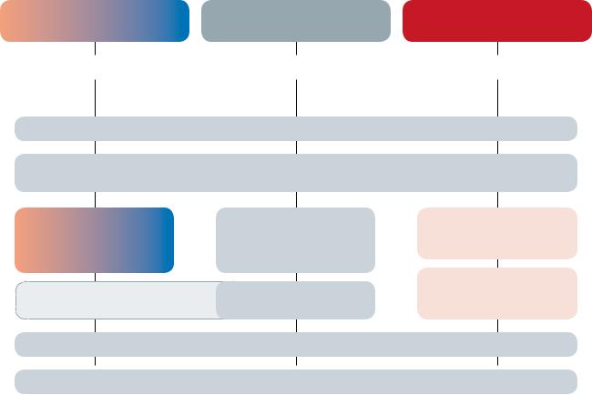
Optimize your working procedures and simultaneously increase the productivity and economic efficiency in your laboratory.
With the IPS InLine metal-ceramic system, you will have the flexibility required for today’s everyday laboratory work – from simple layering to highly esthetic veneers.
The IPS InLine metal-ceramic system permits the fabrication of restorations shaded according to A-D, Chromascop and Bleach shade guides.
After the application of the opaquer, you can choose the product and the corresponding processing procedure according to your personal preferences and the clinical situation:
–IPS InLine One: Uncomplicated one-layer ceramic for quick and efficient layering
–IPS InLine: Conventional metal-ceramic for traditional, individualized layering
–IPS InLine PoM: Press-on-Metal ceramic for accurately fitting, fully anatomical press-on procedures
The IPS InLine System gives you the choice without increasing the number of components. Join in a new way to process metal-ceramic.
IPS InLine
IPS
InLine One
One = One-Layering
IPS
InLine
IPS InLine PoM
PoM = Press-on-Metal
one-layer metal-ceramic |
|
conventional metal-ceramic |
|
press ceramic |
|
|
|
|
|
Alloys from Ivoclar Vivadent
IPS InLine System Opaquer (Paste)
IPS InLine System Opaquer (Powder)
Dentin
7 One Dentcisals Incisal 7 PoM ingots Margin
Deep Dentin
IPS InLine Impulse |
7 PoM Touch Ups |
IPS InLine Gingiva |
|
IPS InLine System Shade / Stains / Glaze
IPS InLine System Add-On (690°C/1274°F)
2

Table of Contents
product |
information |
practical procedure for metal-supported restorations
5 Product Information
IPS InLine System – Metal-Ceramic System
IPS InLine One – One-Layer Metal-Ceramic
IPS InLine – Conventional Metal-Ceramic
IPS InLine PoM – Press-On Metal-Ceramic
Composition
Coordinated Ivoclar Vivadent Alloys
Preparation Guidelines and Minimum Layer Thicknesses
11 IPS InLine One
Framework design criteria Step-by-step IPS InLine One Framework design
Alloy processing / oxide firing Layering diagram IPS InLine One Oqaquer firing
–Paste opaquer
–1st Opaquer firing (wash firing)
–2nd Opaquer firing
–Powder opaquer
–1st Opaquer firing (wash firing)
–2nd Opaquer firing
Individual processing
Stain and characterization firing
Shade adjustment with IPS InLine Shade and Stains Glaze firing
Add-On after glaze firing
27 |
IPS InLine |
|
Framework design criteria |
|
Step-by-step IPS InLine |
|
Framework design |
|
Alloy processing / oxide firing |
|
Layering diagram IPS InLine |
Oqaquer firing
– Paste opaquer
– 1st Opaquer firing (wash firing)
– 2nd Opaquer firing
– Powder opaquer
– 1st Opaquer firing (wash firing)
– 2nd Opaquer firing
IPS InLine Opaquer F (optional)
1st and 2nd Margin firing (optional)
1st Dentin and Incisal firing
2nd Dentin and Incisal firing Margin Add-On firing Add-On material firing Individual processing
Stain and Characterization firing
Shade adjustment with IPS InLine Shade and Stains Glaze firing
Add-On after glaze firing
3

practical procedure information for metal-free resto- rations
46 IPS InLine PoM
Framework design criteria Step-by-step IPS InLine PoM Framework design
Alloy processing / oxide firing Layering diagram IPS InLine PoM Oqaquer firing
–Paste opaquer
–1st Opaquer firing (wash firing)
–2nd Opaquer firing
–Powder opaquer
–1st Opaquer firing (wash firing)
–2nd Opaquer firing
IPS InLine Opaquer F (optional)
Wax-up
Sprueing
Investing
Preheating
Ingot selection
Pressing with the 100g, 200g, 300g IPS investment ring system
Divesting
Separating / finishing
Adjustements with IPS InLine PoM Touch-Up
Individual finishing
Stain and Characterization firing
Shade adjustment with IPS InLine Shade and Stains
Glaze firing
Add-On Glaze firing
70 IPS InLine Veneers
Fabricating the model (refractory die model) Wash firing
Cervical firing
Dentin / Impulse firing Incisal firing
Glaze firing Divesting the veneers
Conditioning the veneers for adhesive cementation
72 General Information
Cementation
IPS InLine One firing parameters IPS InLine firing parameters
IPS InLine PoM Mixing ratio investment material / press parameters / firing parameters IPS InLine Veneer firing parameters
Combination Tables
4
Product Information
IPS IPS
InLine® One – one-layer metal-ceramic InLine® – conventional metal-ceramic
Material
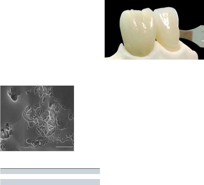
IPS InLine and IPS InLine One are veneering ceramic materials containing leucite. They are suitable for the fabrication of metalceramic restorations at firing temperatures higher than 900 °C (1652 °F). With both products, alloys in the CTE range of 13.8–15.0 x 10⁻⁶/K-1 (25–500°C) can be veneered, irrespective of the metal composition. These ceramics are based on leucite-forming glasses, some of which are produced of feldspar raw materials of a natural origin. Given their composition they demonstrate excellent chemical resistance. With the corresponding mixture and targeted heat treatment of these glasses, leucite crystals with a defined grain size distribution are released in the glass matrix. This results in a
homogeneous structure for the veneering material, which is not only extremely gentle to antagonist but also provides the high strength and convincing optical properties of the IPS InLine veneering ceramic materials.
5 µm
IPS InLine Deep Dentin, IPS InLine Dentin, IPS InLine Transpa Incisal, IPS InLine Gingiva, IPS InLine One Dentcisal:
CTE (25 – 500°C) [10-6 /K]1) |
12.9 ± 0.5 |
Flexural strength (biaxial) [MPa]1) 2) |
≥ 50 |
Chem. solubility [μg/cm2]1) |
≤ 100 |
Firing temperature [°C] |
900 – 930 |
|
|
1)according to ISO 6872:2008
2)typical mean value for the flexural strength is 80 MPa
Classification: Dental ceramics Type 1 / Class 1
Indications
–One-layer veneering ceramic for the most popular dental alloys in the CTE range of 13.8 – 15.0 x 10⁻⁶/K (25 – 500°C) (IPS InLine One)
–Conventional multi-layer veneering ceramic for the most popular dental alloys in the CTE range of 13.8 – 15.0 x 10⁻⁶/K (25 – 500°C) (IPS InLine)
–Veneers on refractory die material (only IPS InLine)
Contraindications
–If patients are known to be allergic to any of the ingredients, the material should not be used.
–Bruxism
–Veneering of titanium and zirconium oxide frameworks
–Any other use not listed in the indications
Important processing restrictions
–Exceeding or falling short of the stipulated veneering layer thicknesses
–Failure to observe the layer thickness ratio between the framework and layering ceramic
–Mixing with and processing in conjunction with other dental ceramics
–Veneering of dental alloys not within the stipulated CTE range
–Failure to observe the necessary minimum connector and framework thicknesses
Side effects
If patients are known to be allergic to any of the components in the materials, IPS InLine One and IPS InLine restorations should not be used.
5

IPS
InLine® PoM – Press-on-Metal ceramic
Material
The IPS InLine PoM ingots are made of a glass-ceramic material containing leucite and based on synthetic glass raw materials, which contain small quantities of an opalescent glass-ceramic in addition to the translucent components. This provides the ingots pressed to full contour with their highly esthetic appearance. The ingots are shaded with pigments, the temperature resistance of which permits the high shade match of the pressed restorations. Both in their pressed and unpressed condition, the ingots demonstrate an iso-tropic structure, which is responsible for its homogeneous distribution of the leucite crystals and the high strength. Another important feature of IPS InLine PoM is its excellent firing stability, which enables the application of Touch-Up materials, Shade, Stains and Glaze without jeopardizing the accuracy of fit of the restoration. The Touch-Up materials are leucite glass-ceramics shaded according to the ingot shade concept. Their thermal expansion and firing temperature are adjusted to suit the application in the cervical area of the ingot after pressing and before the characterization firing cycles.
|
10 µm |
IPS InLine PoM ingots: |
|
|
|
CTE (25 – 500°C) [10-6 /K]1) |
13.2 ± 0.5 |
Flexural strength (biaxial) [MPa]1) 2) |
≥ 50 |
Chem. solubility [μg/cm2]1) |
≤ 100 |
Press temperature [°C] |
940 – 950 |
|
|
1)according to ISO 6872:2008
2)typical mean value for the flexural strength is 130 MPa
Classification: Dental ceramics Type II / Class 1
Indications
–Fully anatomical pressing on masked (opaquerized) crown and bridge metal frameworks
–Pressing on dental alloys with a CTE range of 13.8–14.5 x 10⁻⁶/K (25–500°C) with a silver content of <10%
Contraindications
–Pressing on dental alloys with a CTE outside the stipulated range and not featuring the defined composition
–Alloys with a silver (Ag) content higher than 10%.
–If patients are known to be allergic to any of the ingredients, the material should not be used.
–Pressing on titanium and zirconium oxide frameworks
–Very deep sub-gingival preparations
–Patients with substantially reduced residual dentition
–Bruxism
–Any other use not listed in the indications
Important processing restrictions
–Exceeding or falling short of the stipulated layer thicknesses for press ceramics
–Failure to observe the layer thickness ratio between the framework and layering ceramics
–Failure to observe the necessary minimum connector and framework thicknesses
–Layering with IPS InLine One / IPS InLine layering materials (e.g. Dentcisal, Dentin, Incisal, Deep Dentin, Margin, Impulse and Gingiva materials, etc.)
–Mixing with and processing in conjunction with other dental ceramics
–Pressing over dental alloys not within the stipulated CTE range
Side effects
If patients are known to be allergic to any of the components in the materials, IPS InLine PoM restorations should not be used.
6

Composition
IPS InLine One |
|
|
IPS InLine |
|
IPS InLine PoM |
||||
|
|
|
|
|
|||||
– IPS InLine One Ceramic Materials |
|
– |
IPS InLine Ceramic Materials |
– |
IPS InLine PoM Ingots |
||||
Leucite ceramic based on alcalialumo |
|
|
Leucite ceramic based on alcalialumo |
|
Leucite ceramic based on alcalialumo |
||||
silicate glasses and feldspar |
|
|
silicate |
glasses and feldspar |
|
silicate glasses |
|||
|
|
|
– IPS InLine Margin Build-Up Liquid |
– IPS InLine PoM Touch-Up Materials |
|||||
|
|
|
|
Water and cellulose derivative |
|
Leucite ceramic based on alcalialumo |
|||
|
|
|
|
|
|
|
|
|
silicate glasses |
|
|
|
|
|
|
|
|
– IPS e.max AlOx Plungers |
|
|
|
|
|
|
|
|
|
|
Al2O3 |
|
|
|
|
|
|
|
|
– |
IPS e.max AlOx Plunger Separator |
|
|
|
|
|
|
|
|
|
Boron nitride |
|
|
|
|
|
|
|
|
– IPS PressVEST Powder |
|
|
|
|
|
|
|
|
|
|
SiO2 (quartz powder), MgO and NH4H2PO4 |
|
|
|
|
|
|
|
|
– |
IPS PressVEST Liquid |
|
|
|
|
|
|
|
|
|
Colloidal silicic acid in water |
|
|
|
|
|
|
|
|
– IPS PressVEST Speed Powder |
|
|
|
|
|
|
|
|
|
|
SiO2 (quartz powder), MgO and NH4H2PO4 |
|
|
|
|
|
|
|
|
– IPS PressVEST Speed Liquid |
|
|
|
|
|
|
|
|
|
|
Colloidal silicic acid in water |
|
|
|
|
|
|
|
|||
– |
IPS InLine System Shade / Stains / Glaze |
– |
IPS Model Sealer |
|
|
||||
|
Ceramic materials and glycols |
|
|
|
Ethyl acetate, nitro-cellulose, softener |
||||
– |
IPS InLine System Build-Up Liquids L and P |
– |
IPS Ceramic Separating Liquid |
||||||
|
Water, glycols and additives |
|
|
|
|
Paraffin oil |
|
|
|
– IPS InLine System Powder Opaquer Liquid |
– IPS Margin Sealer |
|
|
||||||
|
Water, glycols, acetic acid, additives |
|
|
Wax dissolved in hexane |
|||||
–IPS InLine System Opaquer Liquid
Butylene glycol, glycerine, thickening agent
–IPS InLine System Glaze and Stains Liquid
Butandiol
Warning
–Hexane is highly flammable and detrimental to health. Avoid contact of the material with skin and eyes. Do not inhale vapours. Keep away from sources of ignition.
–Avoid inhaling grinding dust when working on ceramic restorations. Use suction equipment or protective masks.
7

Coordinated Ivoclar Vivadent alloys
IPS InLine One, IPS InLine ...
are suitable for alloys with a CTE of approximately 13.8 to 15.0 x 10⁻⁶/K at 25–500 °C. If the required framework design with metal scallops (as described on page 25) and the ceramic
layer thickness of max. 1.5 mm are observed, these alloys may be processed using standard cooling in the Programat® furnaces.
IPS InLine PoM ...
is suitable for pressing on alloys with a CTE of 13.8 to 14.5 x 10⁻⁶/K at 25–500 °C and with a maximum silver content of 10 %.
|
IPS InLine One |
IPS InLine PoM |
IPS InLine PoM |
|
CTE |
|
|
|
IPS Investment Ring |
IPS Investment Ring |
|
||
Alloy |
IPS InLine |
|
100/200 g |
300 g |
Colour |
25–500°C |
High gold |
|
|
|
|
|
|
Brite Gold |
* |
|
– |
– |
rich yellow |
14.8 |
Brite Gold XH |
* |
|
– |
– |
rich yellow |
14.4 |
Golden Ceramic |
* |
|
– |
– |
rich yellow |
14.6 |
Callisto 86 |
|
|
|
|
rich yellow |
14.4 |
Aquarius Hard |
* |
|
2) |
2) |
rich yellow |
14.5 |
Aquarius |
* |
|
– |
– |
rich yellow |
14.6 |
d.SIGN 98 |
* |
|
1) |
– |
rich yellow |
14.3 |
Callisto 84 |
|
|
|
|
rich yellow |
14.3 |
Y |
|
|
– |
– |
yellow |
14.6 |
Aquarius XH |
|
|
|
|
yellow |
14.1 |
Y-2 |
* |
|
– |
– |
yellow |
15.0 |
Y-Lite |
|
|
|
|
yellow |
13.9 |
Sagittarius |
|
|
|
|
white |
14.0 |
Y-1 |
* |
|
– |
– |
yellow |
14.8 |
d.SIGN 96 |
|
|
|
– |
yellow |
14.3 |
Reduced gold |
|
|
|
|
|
|
d.SIGN 91 |
|
|
|
|
white |
14.2 |
W |
|
|
– |
– |
white |
14.2 |
W-5 |
|
|
– |
– |
white |
14.0 |
Lodestar |
|
|
|
|
white |
14.1 |
W-3 |
|
|
|
|
white |
13.9 |
Leo |
|
|
|
|
white |
13.9 |
W-2 |
|
|
|
|
white |
14.2 |
Evolution Lite |
|
|
– |
– |
white |
14.2 |
Palladium content |
|
|
|
|
|
|
Spartan Plus |
|
|
|
– |
white |
14.3 |
Spartan |
|
|
|
– |
white |
14.2 |
Capricorn |
|
|
|
|
white |
14.1 |
d.SIGN 84 |
|
|
2) |
2) |
white |
13.8 |
Protocol |
|
|
2) |
2) |
white |
13.8 |
Callisto 75 Pd |
|
|
|
|
white |
13.9 |
Aries |
|
|
– |
– |
white |
14.7 |
d.SIGN 67 |
|
|
– |
– |
white |
13.9 |
d.SIGN 59 |
* |
|
– |
– |
white |
14.5 |
d.SIGN 53 |
** |
|
– |
– |
white |
14.8 |
W-1 |
* |
|
– |
– |
white |
15.2 |
Capricorn 15 |
|
|
– |
– |
white |
14.3 |
Callisto CPG |
|
|
|
|
white |
14.2 |
Implant alloys |
|
|
|
|
|
|
Callisto Implant 78 |
|
|
|
|
white |
13.9 |
Callisto Implant 33 |
|
|
|
|
white |
14.0 |
IS-64 |
** |
|
– |
– |
white |
14.8 |
Callisto Implant 60 |
** |
|
– |
– |
white |
14.5 |
Free of precious metals |
|
|
|
|
|
|
Colado NC |
|
|
|
|
white |
14.0 |
4all |
|
|
2) |
2) |
white |
13.8 |
d.SIGN 30 |
** |
|
2) |
2) |
white |
14.5 |
Colado CC |
** |
|
2 |
2) |
white |
14.2 |
|
* Cooling to 800 °C / 1472 °F |
1) Single restorations |
The range of available alloys may vary from country to country. |
|||
|
** Cooling to 700 °C / 1292 °F |
2) see ”Important” next page |
|
|
||
8

Important
IPS InLine One, IPS InLine
–If these minimum requirements cannot be observed, cooling to *800 °C, or **700 °C (depending on the alloy type), is required in conjunction with all main firings and glaze firings.
–With ceramic layer thicknesses of over 1.5 mm up to max. 2.5 mm, as well as with voluminous restorations (e.g. implant-retained reconstructions) in combination with high gold and base metal alloys, cooling to *800 °C or ** 700 °C must be conducted. This also applies to soldered restoratios.
Important
IPS InLine PoM
–With alloys in the lower CTE range of 13.8 x 10⁻⁶/K at 25–500 °C and the upper range of
14.5 x 10⁻⁶/K at 25–500 °C, no ceramic shoulders should be used. With such framework geometries (shoulder) or non-metal-supported areas, the cooling and tension conditions are critical. For ceramic shoulders, alloys in the CTE range of approximately 14.0 to 14.3 x 10⁻⁶/K at 25–500 °C are recommended.
–For single restorations – particularly with ceramic shoulders – only the 200g or 300g investment rings should be used, since the expansion values as well as the cooling and tension conditions are ideally coordinated.
Important
IPS InLine System Powder Opaquer
–Alloys (CTE of approx. 13.8 to 15.0 x 10⁻⁶/K at 25–500 °C) with a solidus point of ≥ 1080 °C are suitable for opaquerizing with the powder opaquer at a firing temperature of 960 °C.
9

Preparation guidelines and minimum layer thicknesses
The preparation must provide sufficient space to achieve stable and esthetic metal-ceramic restorations. The usual preparation guidelines for metal-ceramics apply for the IPS InLine System. As usual for metal-supported restorations, dentists may use conventional cementation.
A chamfer preparation is suitable for tapered metal margins. For metal-supported inlays, partial crowns and inlay-retained bridges that are seated using conventional cementation, a chamfer preparation is indicated to minimize the cement gap. The margin is designed in metal. For esthetically pleasing single crowns and bridge abutment crowns, a ceramic shoulder should be provided. For that purpose, a shoulder preparation is required. With adhesive cementation, the margin can be designed in the ceramic. However, the margin should not be bevelled in such cases, since thin, non-metal-supported margins demonstrate a fracture risk.
IPS InLine One |
IPS InLine |
IPS InLine PoM |
One-layer metal-ceramic |
Conventional metal-ceramic |
Press-on-Metal ceramic |
Minimum dimensions for metal frameworks |
Minimum dimensions for metal frameworks |
Minimum dimensions for metal frameworks |
– Crowns min. 0.3 mm |
– Crowns min. 0.3 mm |
– Crowns min. 0.3 mm |
– Abutment crowns min. 0.5 mm |
– Abutment crowns min. 0.5 mm |
– Abutment crowns min. 0.5 mm |
Minimum ceramic layer thickness |
Minimum ceramic layer thickness |
Minimum ceramic layer thickness |
– IPS InLine One min. 0.8 mm |
– IPS InLine min. 0.8 mm |
– IPS InLine PoM min. 0.8 mm |
|
|
|
|
2.0 |
2.0 |
|
.2 |
|
>1.2 |
1.5 |
1.5 |
|
>1.2 |
>1.2 |
|
1.5 |
|
–With conventional cementation, a minimum height of 3 mm of the prepared tooth and a convergence angle of approx. 6° must be observed.
–The following minimum connector dimensions should be observed for bridge restorations: The connector dimensions depend on the selected alloy and the pontic width (see Framework Design Guidelines, page 9).
Veneers on refractory die material
Dimensions in mm
10
IPS InLine® One – one-layer metal-ceramic
Framework design criteria
The framework design is key to the success of durable metal-ceramic restorations. The more attention given to the framework design, the better the final results and the clinical success will turn out to be.
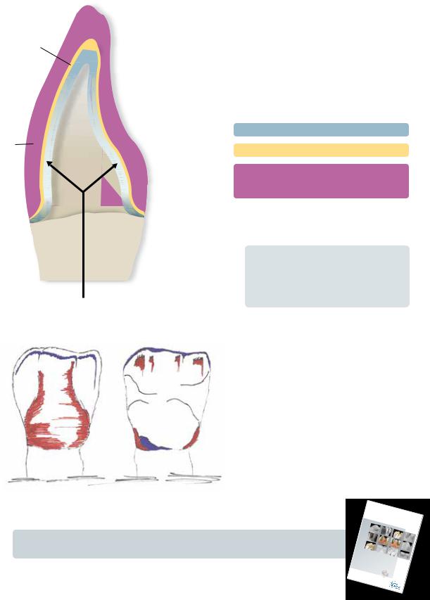
1. Functional support of the veneering ceramic
The framework reflects the shape of the tooth in a reduced form. It should be designed in such a way that it supports the cusps and incisal edges resulting in a virtually even layer thickness of the veneering ceramic in the cusp-fissure area. In this way, the masticatory forces occurring during functional chewing are exerted on the framework rather than on the veneering ceramic. Therefore, the framework must not show any angles and edges (see diagram) so that the masticatory forces do not result in tension peaks, which may cause delamination and cracks. Such angles and edges should already be rounded off in the wax-up, not as late as in the metal. The wall thickness of the metal framework for single crowns must not be less than 0.3 mm and for bridge abutments 0.5 mm after finishing (see diagram). Please refer to the Instructions for Use of the corresponding alloy for further information.
Anterior crowns
correct |
wrong |
Premolar crowns
correct |
wrong |
Molar crowns
correct |
wrong |
Ceramic-Metal Layer-One – One IPSInLine
11

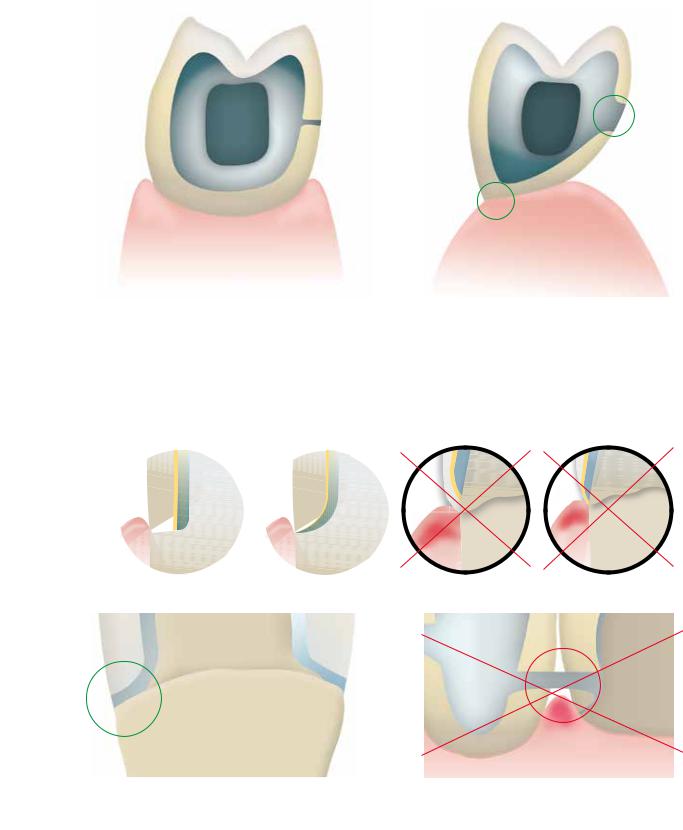
2. Framework design for fired ceramic shoulders
With fired ceramic shoulders, make sure that the framework rather than the veneer is supported by the prepared tooth. The framework is thus reduced exactly to the inner edge of the chamfer or shoulder preparation to achieve functional support of the framework on the preparation. Excellent accuracy of fit on the preparation is essential to ensure that the shoulder material may not reach the inner aspects of the framework during subsequent application.
correct |
wrong |
3. Framework stability
The dimensions and shape of the interdental connector surfaces significantly influence the stability of the restoration during processing as well as the clinical long-term success after incorporation. Therefore, the dimensions of the interdental connector surface must be designed in accordance with the alloy used (take the 0.2% proof stress into account)! The thermal behaviour of the selected alloy during processing has to be considered when designing the framework.
Single connector width |
Double the width of the |
Double the height of the |
= single stability |
connector |
connector with single width |
|
= double the stability |
= eightfold stability |
12
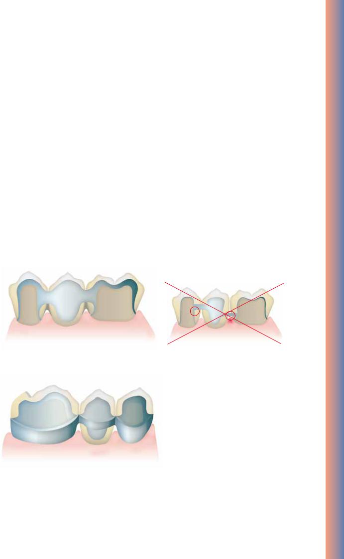
4. Framework design for bridges
Thermal stress during firing and masticatory forces after cementation affect metal frameworks. These forces must be transferred on the framework rather than the veneer. Particularly in the connector areas between bridge abutments and bridge pontics in bridge reconstructions, the stability must be ensured with the help of the framework design and adequate framework material thickness. The framework design and framework thickness must therefore meet all the optical and functional requirements, as well as the aspects of periodontal hygiene. A full wax-up with the corresponding reduction of the ceramic provides the most predictable results.
During veneering with ceramic materials, the bridge framework is exposed to high temperatures several times. With an inappropriate framework design or insufficient framework thickness, the high temperatures during firing may result in distortion or inaccuracy of fit of the framework. A scallop-type design with e.g. interproximal reinforcements counteracts this development. Additionally, this framework design (e.g. with cooling struts) ensures more even cooling of the restoration during the cooling phase. This is particularly important for high gold alloys.
In order to enable optimum oral hygiene with bridge restorations, the design of the interdental spaces should be given special attention. Adequate opening of the interdental area without creating black triangles should be given special attention in order to ensure proper periodontal hygiene with interdental brushes and dental floss.
correct |
wrong |
correct
Ceramic-Metal Layer-One – One IPSInLine
13
5. Design of bridge pontics
Bridge pontics are designed with esthetic and functional aspects as well as oral hygiene in mind. The area of the pontic that contacts the alveolar ridge should be made of ceramic.
In order to ensure adequate stability between the bridge pontic and the bridge abutments, a palatal and/or lingual scallop is recommended. Furthermore, to ensure even cooling of the bridge pontic that absorbs the most heat, additional cooling struts are advantageous.
Bridge pontic design – ovate pontic |
Bridge pontic design – saddle-type pontic |
6. Interface between metal and ceramic
The interface between the metal framework and the veneering ceramic must be clearly defined. If possible, incorporate a right angle finish line. The junctures between the metal framework and the veneering ceramic must neither be located in the contact area nor on surfaces involved in masticatory functions. The interface in the interdental area should be designed in such a way that cleaning of these hard-to-reach areas is possible.
|
|
|
|
|
wrong |
|
wrong |
|
|
|
|
|
|
||
|
|
|
|
|
|
||
|
|
|
|
|
|
||
|
|
|
|
|
|
||
|
|
|
|
|
|
||
correct |
correct |
14
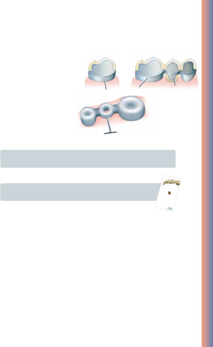
Holding pins
In order not to damage the crown wall during processing, the crown and bridge frameworks are provided with holding pins. They are directly attached to the framework with the help of wax. Dimensions of Ø 0.5–1.0 mm for the holding pins have proven to be useful. They can be used to secure the framework by means of holding clips. Furthermore, the holding pins also act as cooling struts during casting and firing.
Important
The holding pins must be placed in such a way that they do not interfere during try-in or in the articulator. They should only be removed without causing overheating once the restoration has been completed.
Please refer to the “Framework Design Guidelines for Metal-Ceramic Restorations” for additional |
|
|
|
|
|
|
|
|
information on framework design. They can be ordered from your Ivoclar Vivadent contact |
|
|
|
|
|
|
|
|
address. |
F R |
e t a l -c e rOa |
R K D |
|
|
|
||
|
A M |
E W |
|
|
|
|
|
|
|
f o r m |
|
|
|
|
|
|
|
|
|
|
|
m i c r e s |
|
E S |
I G |
N |
|
|
|
Manual |
t o r a |
|
|||
|
|
|
|
|
t i o n s |
|||
Ceramic-Metal Layer-One – One IPSInLine
15

Step-by-step
Starting situation
Maxillary and mandibular model articulated in the “Stratos 200” |
Starting situation for metal-supported IPS InLine restorations |
Framework design
Design the framework with a reduced anatomical shape taking the planned layering into account. The wall thickness for single crowns should be at least 0.3 mm and at least 0.5 mm for abutment crowns.
Make sure to provide sufficient stability of shape for the framework. Avoid sharp transitions and edges. Design the connector areas between the individual units in such a stable way that they meet the requirements of interdental hygiene and the alloy used.
Design the framework in a reduced supported shape.
16
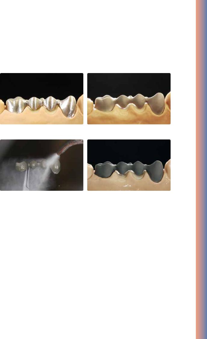
Alloy processing / oxide firing
The cast metal framework is finished using tungsten carbide burs or ceramic-bonded grinding instruments.
Metal framework before blasting |
Carefully blast the framework with aluminium oxide Al2O3 50–100 µm |
|
(observe the instructions of the alloy manufacturer). |
Ceramic-Metal Layer-One – One IPSInLine
After blasting, clean the metal framework with a steam jet and allow to dry thoroughly. Conduct the oxide firing according to the instructions of the manufacturer.
After oxide firing, the framework should exhibit an evenly oxidized surface.
17
IPS InLine One layering diagram
Opaquer
|
Ideal layer |
Limited layer |
|
thickness |
thickness |
Framework |
0.3–0.5 mm |
0.3–0.5 mm |
Dentcisal |
0.1 mm |
0.1 mm |
Opaquer |
||
Dentcisal |
|
|
cervical |
0.8 mm |
0.5 mm |
incisal |
1.5 mm |
0.8 mm |
|
|
|
These figures are drawn from past experience and they may vary in certain situations.
Note:
Metal framework thickness: – Crowns min. 0.3 mm
– Bridge abutments min. 0.5 mm
To enhance the chroma in thin layers, IPS InLine Deep Dentin in the corresponding opaquer shade may be thinly applied on the opaquer.
|
Halo effect |
Opalescence effect |
Stains vanilla |
Shade Incisal 1 |
Mamelon effect |
|
|
|
Stains vanilla, |
|
Shade Incisal 1 |
|
Brightness value |
|
Stains white |
Shade=Hue A1 etc… |
|
Shade 1 |
Chroma |
|
|
|
Stains red |
|
Chroma |
|
Stains orange |
Depending on the desired individualization, IPS InLine System Shade/Stains can be used to achieve true-to-nature shade effects.
Shade |
Stains |
S |
InLineMetal- |
k |
|
IP |
|
Press-on- |
|
|
Kerami |
®
PoM
You can find additional information on esthetic individualization in the edition “Love for Detail” by D. Grübel. It can be ordered from your Ivoclar Vivadent contact address.
Edition LIEBE ZUM
ÄSTHETIK UND MORPHOLOGIE
18
Opaquer Firing
Paste opaquer
1st Opaquer firing (wash firing) (paste opaquer)
Select the IPS InLine System Opaquer paste in the corresponding tooth shade. If required, homogenize the opaquer paste by stirring it before taking it from its jar. Extrude the desired amount from the syringe or jar and mix thoroughly on the mixing pad. Thin it, if required. Apply the first opaquer layer thinly and agitate it into the alloy surface. After firing and cooling, clean the opaquerized metal framework with the steam jet and dry with oil-free air.
Tip:
The consistency of the paste opaquer can be individually adjusted using the IPS InLIne System Opaquer Liquid.
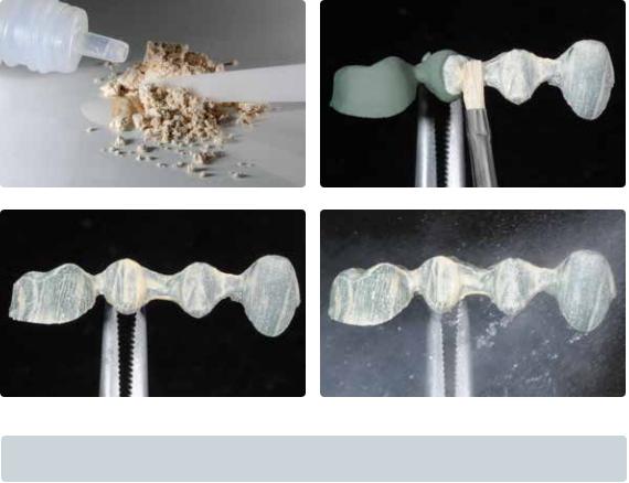
2nd Opaquer firing (paste opaquer)
Apply the second opaquer layer in such a way that the metal framework is entirely covered with opaquer. After firing, the IPS InLine System Opaquer should show a covering, silky-mat shiny surface. After the opaquer firing, the conditioned surfaces of the alloy framework should be entirely covered with opaquer.
Important
The firing tray with the opaquerized metal framework should only be placed in the firing chamber and removed from it once the furnace head is completely open and the beeper has sounded.
Firing parameters IPS InLine System Opaquer (paste opaquer), 1st and 2nd Opaquer firing |
|
|||||
T |
B |
S |
t |
H |
V1 |
V2 |
°C/°F |
°C /°F |
min |
°C/°F/min |
min |
°C/°F |
°C/°F |
930/1706 |
403/ 757 |
6 |
100/180 |
2 |
450/842 |
929/1704 |
|
|
|
|
|
|
|
Ceramic-Metal Layer-One – One IPSInLine
19
Powder opaquer
1st Opaquer firing (wash firing) (powder opaquer)
Select the IPS InLine System Powder Opaquer in the corresponding tooth shade. Remove the amount of powder opaquer required for the wash from the jar and mix it thoroughly with the Powder Opaquer Liquid on the mixing pad until it has reached the desired consistency. Apply the first opaquer layer thinly on the metal framework and agitate it into the alloy surface. After firing and cooling, clean the opaquerized metal framework with the steam jet and dry with oil-free air.
Important
Mix IPS InLine System Powder Opaquer only with the Powder Opaquer Liquid.
20
2nd Opaquer firing (powder opaquer)
Remove the amount of powder opaquer required for the covering layer from the jar and mix it together with the remaining, dried up “wash opaquer” on the mixing pad. Then, mix the powder opaquer with the Powder Opaquer Liquid until it has reached the desired consistency.
Apply the second opaquer layer evenly and in such a way that the metal framework is entirely covered with opaquer. After firing according to the stipulated firing parameters, the IPS InLine System Powder Opaquer should show a covering, silkymat shiny surface. After the opaquer firing, the conditioned surfaces of the alloy framework should be entirely covered with opaquer.
Tip:
A glass or ceramic instrument is optimally suitable to apply the IPS InLine Powder Opaquer for the opaquer firing. Naturally, a brush can also be used to apply IPS InLine Powder Opaquer.
The IPS InLine System Powder Opaquer and Powder Opaquer Liquid are ideally suitable for the application with conventional spray-on techniques. Mix the powder opaquer to a thin consistency, depending on the sprayon system used. Observe the instructions of the manufacturer of the spray-on systems.
Important
•Use distilled water to rewet the mixed or the already applied powder opaquer.
•The firing tray with the opaquerized metal framework should only be placed in the firing chamber and removed from it once the furnace head is completely open and the beeper has sounded.
Firing parameters IPS InLine System Opaquer (powder opaquer), 1st and 2nd Opaquer firing |
|
|||||
T |
B |
S |
t |
H |
V1 |
V2 |
°C/°F |
°C/°F |
min |
°C/°F/min |
min |
°C/°F |
°C/°F |
960/1760 |
403/757 |
4 |
100/180 |
2 |
450/842 |
959/1758 |
|
|
|
|
|
|
|
Important
IPS InLine System Powder Opaquer
–Alloys (CTE of approx. 13.8 to 15.0 x 10⁻⁶/K at 25-500 °C) with a solidus point of ≥ 1080 °C are suitable for opaquerizing with the powder opaquer at a firing temperature of 960 °C.
Ceramic-Metal Layer-One – One IPSInLine
21

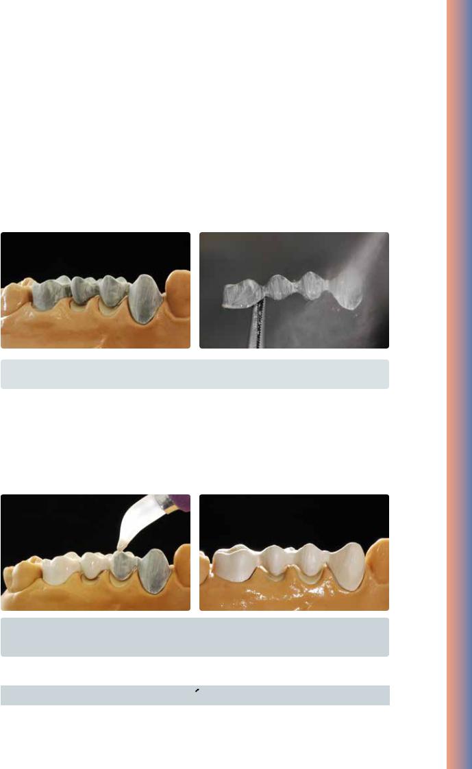
1st Dentcisal firing
Isolate the model before layering the Dentcisal material. In this way, the ceramic material is prevented from drying out or sticking to the model. Isolate the stone die and the adjacent areas using IPS Model Sealer. Additionally,
separate the area of the pontics with IPS Ceramic Separating Liquid.
Tip:
To achieve an optimum bond between the ceramic material and the opaquer surface, apply a small amount of IPS InLine One Dentcisal material to the cervical and interdental areas (for bridges) and slightly roughen it.
Make sure that the restoration is slightly overcontoured so that the actual tooth shape is achieved after firing. After lifting the bridge off the model, supplement the contact points with Dentcisal materials. Before firing, separate the entire interdental area down to the opaquer.
Tip:
Densify the ceramic surface (after contouring) with a large, dry brush toward the cervical margin before firing.
The ceramic material is applied according to the individual situation. |
For an optimum firing result, the interdental areas must be separated down to the opaquer. |
Restoration after the 1st Dentcisal firing
Important
•Use distilled water to rewet the mixed or even already applied layering material.
•The firing tray with the restoration should only be placed in the firing chamber and removed from it once the furnace head is completely open and the beeper has sounded.
Firing parameters 1st Denticisal firing |
|
|
|
|
|
||
T |
B |
|
S |
t |
H |
V1 |
V2 |
°C/°F |
°C/°F |
|
min |
°C/°F/min |
min |
°C/°F |
°C/°F |
910/1670 |
403/757 |
|
4 |
60/108 |
1 |
450/842 |
909/1668 |
|
|
|
|
|
|
|
|
22
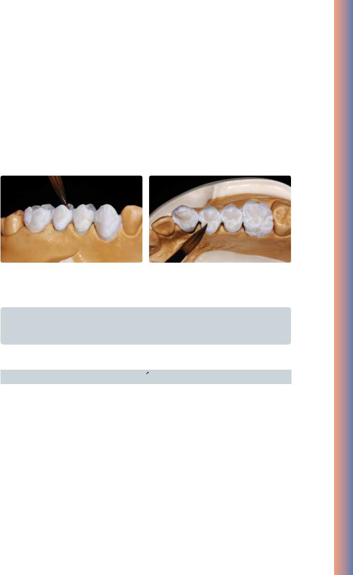
2nd Dentcisal firing
Finish and thoroughly clean the restoration. Clean under running water or with the steam jet. Blasting the restoration with Al2O3 (type 50) at 1 bar (15 psi) pressure is only necessary if there is superficial contamination after cleaning. Thoroughly dry the restoration and complete the missing areas. Pay special attention to interdental spaces as well as contact points. Place the completely layered restoration on the firing tray and ensure adequate support. The firing tray with the restoration should only be placed in the firing chamber once the furnace head is completely open and the beeper has sounded. Use the firing parameters stipulated below to fire the restoration.
Ceramic-Metal Layer-One – One IPSInLine
Supplementing the restoration with Dentcisal material |
Final design of the occlusal surface |
Important
•Use distilled water to rewet the mixed or even already applied layering material.
•The firing tray with the restoration should only be placed in the firing chamber and removed from it once the furnace head is completely open and the beeper has sounded.
Firing parameters 2nd Denticisal firing |
|
|
|
|
|
||
T |
B |
|
S |
t |
H |
V1 |
V2 |
°C/°F |
°C /°F |
|
min |
°C/°F/min |
min |
°C/°F |
°C/°F |
900/1652 |
403/757 |
|
4 |
60/108 |
1 |
450/842 |
899/1650 |
|
|
|
|
|
|
|
|
23

Individual finishing
Finishing and preparing for the Stains and Glaze firing
Before the Stains and Glaze firing, the restoration has to be prepared as follows:
–Finish the restoration using diamond grinders and give it a true-to-nature shape and surface structure, such as growth lines and convex/concave areas.
–Areas which should exhibit a higher gloss after Glaze firing (e.g. pontic rests) can be smoothed out and prepolished using silicone disks.
–If gold and/or silver dust was used to visualize the surface texture, the restoration has to be thoroughly cleaned with steam. Make sure to remove all gold or silver dust in order to avoid any discolouration after firing.
The true-to-nature shape and surface texture are designed.
Stains and Characterization firing
Before the Stains and Characterization firing, the restoration must be free of dirt and grease. Any contamination after cleaning must be prevented. The following steps must be observed:
–For better wetting of the stains, IPS InLine/IPS InLine PoM Glaze and Stains liquid may be slightly rubbed into the surface.
–If a more intensive shade effect is desired, it is achieved by several staining procedures and repeated firing. The application of too many stains results in an unnatural shade effect.
–The cusps and fissures can be individualized using Stains.
–The basic chromatic shade is supported with the corresponding Shade material (see table).
Shade combination table for IPS InLine One / IPS InLine / IPS InLine PoM
|
Shade |
1 |
2 |
3 |
4 |
5 |
6 |
7 |
SI1 |
SI2 |
|
|
|
||||||||||
|
|
|
|||||||||
|
A-D |
A1, B1, B2 |
A2, A3, A3.5 |
B3, B4, D4 |
A4 |
C1, D2, D3 |
C2, C3, C4 |
– |
A1, A2, A3, B1, |
A3.5, A4, C1, |
|
|
C2, C3, C4, D2, |
|
|||||||||
|
|
|
|
|
|
|
|
B2, B3, B4 |
|
||
|
|
|
|
|
|
|
|
|
D3, D4 |
|
|
|
|
|
|
|
|
|
|
|
|
|
|
|
|
|
|
|
|
|
|
|
|
|
|
|
Chromascop |
110, 120, 130 |
140, |
|
|
|
410, 420, |
520, 530 |
110–140, 210, |
230, 240, 330, |
|
|
|
BL1, BL2, BL3, |
210, 220, 230, |
310, 320, 330 |
340, 540 |
– |
430, 440, |
|
220, 310, 320, |
340, 410–440, |
|
|
|
BL4 |
240 |
|
|
|
510 |
|
BL1–BL4 |
510–540 |
|
|
|
|
|
|
|
|
|
|
|
|
|
Firing parameters for the IPS InLine System Shade/Stains firing |
|
|
|
|||
|
|
|
|
|
|
|
T |
B |
S |
t |
H |
V1 |
V2 |
°C/°F |
°C/°F |
min |
°C/°F/min |
min |
°C/°F |
°C/°F |
850/1562 |
403/757 |
6 |
60/108 |
1 |
450/842 |
849/1560 |
|
|
|
|
|
|
|
24

Shade adjustment with IPS InLine System Shade and Stains
These stains may be fired in a separate Stains firing. Minor shade adjustments and individual characterizations may also be fired in the Glaze firing.
Dispense the desired quantity of IPS InLine System Shade and dilute and mix with IPS InLine System Glaze and Stains Liquid to the desired consistency. Pooling should be avoided and the material must not be applied too thickly. If a more intensive shade effect is desired, it is achieved by several staining procedures and repeated firing. The application of too many stains results in an unnatural shade effect.
Firing parameters for the IPS InLine System Shade/Stains firing (Stains and Characterization firing) |
|
||||||
|
|
|
|
|
|
|
|
T |
B |
S |
t |
H |
V1 |
|
V2 |
°C/°F |
°C/°F |
min |
°C/°F/min |
min |
°C/°F |
|
°C/°F |
850/1562 |
403/757 |
6 |
60/108 |
1 |
450/842 |
|
849/1560 |
|
|
|
|
|
|
|
|
Additional Stains and Characterization firing cycles can be conducted with the same firing parameters.
Glaze firing
After the Stains and Characterization firing with IPS InLine System Shade/Stains, the Glaze firing is conducted.
–If required, homogenize the Glaze paste by stirring it before taking it from its jar. Extrude the desired amount of
IPS InLine System Glaze paste from the syringe or jar and mix thoroughly on the mixing pad. If a different consistency is desired, adjust the consistency by diluting the material with IPS InLine System Glaze and Stains Liquid. Next, apply the Glaze material in the usual manner using a brush. Make sure not to apply the Glaze material either in too thick or too thin layers.
–Minor shade adjustments may be carried out together with the Glaze firing.
Firing parameters for the Glaze firing |
|
|
|
|
|
||
|
|
|
|
|
|
|
|
T |
B |
|
S |
t |
H |
V1 |
V2 |
°C/°F |
°C/°F |
|
min |
°C/°F/min |
min |
°C/°F |
°C/°F |
850/1562 |
403/757 |
|
6 |
60/108 |
2 |
450/842 |
849/1560 |
|
|
|
|
|
|
|
|
When working with a furnace from other manufacturers these parameters have to be adjusted accordingly! Finally, the shade of the completed restoration is checked.
If less gloss is desired, the holding time can be reduced to 1 minute.
If the gloss is unsatisfactory after the first Glaze firing, further Glaze firing procedures may be conducted using the same firing parameters.
Add-On after Glaze firing
Mix the IPS InLine System Add-On 690 °C/1274 °F material with the desired build-up liquid, apply on the missing areas, and fire.
Firing paramters for the Add-On |
690°C/1274°F after Glaze firing |
|
|
|
||||
|
|
|
|
|
|
|
|
|
T |
B |
|
S |
t |
|
H |
V1 |
V2 |
°C/°F |
°C/°F |
|
min |
°C/°F/min |
|
min |
°C/°F |
°C/°F |
690/1274 |
403/757 |
|
4 |
60/108 |
|
1 |
450/842 |
689/1272 |
|
|
|
|
|
|
|
|
|
Ceramic-Metal Layer-One – One IPSInLine
25

Individually designed and characterized bridge made of IPS InLine One
26

IPS InLine® – Conventionally Layered
Framework design criteria
The framework design is key to the success of durable metal-ceramic restorations. The more attention given to the framework design, the better the final results and the clinical success will turn out to be.
1. Functional support of the veneering ceramic
The framework reflects the shape of the tooth in a reduced form. It should be designed in such a way that it supports the cusps and incisal edges resulting in a virtually even layer thickness of the veneering ceramic in the cusp-fissure area. In this way, the masticatory forces occurring during functional chewing are exerted on the framework rather than on the veneering ceramic. Therefore, the framework must not show any angles and edges (see diagram) so that the masticatory forces do not result in tension peaks, which may cause delamination and cracks. Any sharp angles or edges should be removed in the waxup rather than by grinding the metal framework. The wall thickness of the metal framework for single crowns must not be less than 0.3 mm and for bridge abutments 0.5 mm after finishing (see diagram). For further information, please refer to the Instructions for Use of the corresponding alloy.
Anterior crowns
correct |
wrong |
Premolar crowns
correct |
wrong |
Molar crowns
correct |
wrong |
Layered Conventionally – IPSInLine
27
 Loading...