


Programat®
EP 3000 G2
Operating Instructions
Valid |
as of |
.0 |
|
|
|
|
|
||
Software |
Version |
6 |
|
|
|
|
|||
|
|
|
||
|
|
|
|
|
|
|
|
|
|
2
Table of Contents
Views of the Furnace, List of Parts |
4 |
|
1. |
Introduction / Signs and Symbols |
8 |
1.1 |
Preface |
|
1.2 |
Introduction |
|
1.3 |
Notes regarding the Operating Instructions |
|
1.4Notes on the different voltage versions
2. |
Safety First |
9 |
2.1 |
Indications |
|
2.2 |
Health and safety instructions |
|
3. |
Product Description |
12 |
3.1 |
Components |
|
3.2 |
Hazardous areas and safety equipment |
|
3.3 |
Functional description |
|
3.4 |
Accessories |
|
4. |
Installation and Initial Start-Up |
13 |
4.1 |
Unpacking and checking the contents |
|
4.2 |
Selecting the location |
|
4.3 |
Assembly |
|
4.4 |
Removing the furnace head |
|
4.5Initial start-up
5. |
Operation and Configuration |
19 |
5.1 |
Introduction to the operation |
|
5.2 |
Explanation of the key functions |
|
5.3 |
Program structure |
|
5.4 |
Adjustable parameters and possible value ranges |
|
5.5 |
Settings and information |
|
5.6 |
Explanation of the symbols on the display |
|
5.7 |
Explanation of the speaker signals |
|
6. |
Practical Use |
25 |
6.1 |
Switching on/off |
|
6.2 |
Firing programs |
|
6.3 |
Press programs |
|
6.4 |
Other options and special features of the furnace |
|
7. |
Maintenance, Cleaning and Diagnosis |
29 |
7.1 |
Monitoring and maintenance |
|
7.2 |
Cleaning |
|
7.3Temperature calibration
7.4Service note
7.5Stand-by
7.6Replacing the press plunger
8. |
What if... |
32 |
8.1 |
Error messages |
|
8.2 |
Technical malfunctions |
|
8.3 |
Repair |
|
8.4 |
Load factory settings |
|
9. |
Product Specifications |
35 |
9.1 |
Delivery form |
|
9.2 |
Technical data |
|
9.3 |
Acceptable operating conditions |
|
9.4 |
Acceptable transportation and storage conditions |
|
10. |
Appendix |
36 |
10.1 |
Program table |
|
10.2 |
Menu structure |
|
3

List of parts
1 |
Sealing surface |
34 |
Cooling tray |
2 |
Furnace head sealing ring |
35 |
Screw for cooling tray |
3 |
Insulation |
36 |
Hood |
4 |
Thermocouple |
37 |
Knurled screw for hood |
5 |
Firing plate 2 |
38 |
Air vents furnace head |
6 |
Display |
39 |
Air vents rear panel |
7 |
Frame plate |
40 |
Warnings |
8 |
QTK heating muffle |
41 |
Furnace head mounting mark |
9 |
Housing base |
42 |
Furnace base mounting mark |
10 |
Keypad (membrane-sealed) |
43 |
Furnace head mounting |
11 |
On/Off switch |
44 |
Quartz-glass tube |
12 |
Heating element fuse |
46 |
Vacuum hose |
13 |
Vacuum pump fuse |
47 |
Silicone washer |
15 |
Fuse holder |
48 |
Firing plate holder |
16 |
Power cord |
49 |
Thermocouple cable |
17 |
Power socket |
50 |
Connecting rod axis |
18 |
Vacuum pump socket |
53 |
USB interface |
19 |
Rating plate |
54 |
Plug-in console |
20 |
Screw for furnace head cover |
56 |
Cover for press drive |
21 |
Vacuum hose connection |
58 |
Furnace head, compl. |
22 |
Head insulation |
59 |
Press plunger 120 |
23 |
Rubber feet |
60 |
Press drive plug |
25 |
Housing furnace head |
61 |
Press electronics |
26 |
Thermocouple plug |
62 |
Cover for press electronics |
27 |
Plug fuse |
63 |
Fan |
28 |
Heater plug |
64 |
Split taper socket for press plunger |
29 |
Heater plug socket |
65 |
Terminal screw for press plunger |
30 |
Thermocouple plug socket |
66 |
Press drive cable |
32 |
Leaf spring |
67 |
Press drive plug socket |
33 |
Air vents (base) |
|
|
Please note that the list of parts applies to the entire Operating Instructions. These parts and their numbers are often referred to in later chapters.
4

56 
38
25
40
6
35 34
10 |
23 |
20
58
63
3
36
33 
9
8  2
2
5 1
7
5

62
61
 63
63
36
37
64
65
 39 22
39 22
22
59
11 |
12 |
13 |
53 |
19 |
|
|
21 |
|
|
46 |
|
|
17 |
11 |
|
16 |
|
|
19 |
12 |
|
18 |
15 |
13 |
53 |
|
32 43
11 |
49 |
66 |
26 |
30 |
60 67 |
29 |
27 |
28 |
6

3
8
4
59 |
41 |
|
|
|
42 |
 44
44
Control unit:
70 Program key
71 ESC key
72 ENTER key
73 START key
74 Start LED
75 STOP key
76 Plus key
77 Minus key
78 Settings / Information
79 Cursor key right
80 Cursor key left
81 Stand-by temperature
82 Closing time
83 Temperature increase
84 Holding temperature
85 Holding time
86 Vacuum on
87 Vacuum off
88 Long-term cooling
89 Power Saving key
90 Open furnace head
91 Close furnace head
92 Numeric keys
93 Firing / Pressing
94 Home key
78 |
|
|
|
|
|
|
|
93 |
|
|
|
|
|
|
90 |
|
|
|
|
|
|
|
|
94 |
|
|
|
|
|
|
91 |
|
|
|
|
|
|
|
|
84 |
|
|
|
|
|
|
|
87 |
|
|
|
|
|
|
|
89 |
|
|
|
|
|
|
75 |
88 |
|
|
|
|
|
|
73 |
|
|
|
|
|
|
||
86 |
|
|
|
|
|
|
|
83 |
|
|
|
|
|
|
74 |
|
|
|
|
|
|
|
|
81 |
|
|
|
|
|
|
|
82 |
|
|
|
|
|
|
|
85 |
|
|
|
|
|
|
|
|
|
|
|
|
|
|
92 |
80 |
79 |
70 |
71 |
77 |
76 |
72 |
|
|
|
|
100 |
|
|
|
|
100Programat firing tray
101Metal pin A
102Metal pin B
103Metal pin C
|
102 |
103 |
101 |
110 USB data cable |
115 Cooling grid (complete) |
120 Automatic Temperature |
|
|
|
|
Checking Set 2 – ATK 2 |
110 |
|
|
120 |
115
7
1. Introduction / Signs and Symbols
1.1 Preface
Dear Customer
Thank you for having purchased the Programat EP 3000/G2. It is a state-of-the-art furnace for dental applications.
The furnace has been designed according to the latest industry standards. Inappropriate use may damage the equipment and be harmful to personnel. Please observe the relevant safety instructions and read the Operating Instructions carefully.
Enjoy working with the
Programat EP 3000/G2.
1.2 Introduction
The signs and symbols in these Operating Instructions and on the furnace facilitate the finding of important points and have the following meanings:
Risks and dangers
Important information
Contraindication
Burn hazard
Risk of crushing
The Operating Instructions must be read
1.3Notes regarding the Operating Instructions
Furnace concerned:
Programat EP 3000/G2
Target group:
Dental technologists
These Operating Instructions facilitate the correct, safe, and economic use of the Programat EP 3000/G2 furnace.
Should you lose the Operating Instructions, extra copies can be ordered at a nominal fee from your local Ivoclar Vivadent Service Center or downladed from www.ivoclarvivadent.com/ downloadcenter.
In the Operating Instructions, the furnace is described in the 200–240 V voltage version.
Please note that the voltage range shown on the images (e.g. rating plate) may differ depending on the voltage version of your furnace.
1.4Notes on the different voltage versions
The furnace is available with different voltage versions.
– 110 – 120 V / 50 – 60 Hz – 200 – 240 V / 50 – 60 Hz
In the Operating Instructions, the furnace is described in the 200 – 240 V voltage version.
Please note that the voltage range shown on the images (e.g. rating plate) may differ depending on the voltage version of your furnace.
8
2. Safety First
This chapter is especially important for personnel who work with the Programat EP 3000/G2 or who have to carry out maintenance or repair work. This chapter must be read and the corresponding instructions followed.
2.1 Indications
The Programat EP 3000/G2 must only be used to fire and/or press dental ceramic materials and it should be used for this purpose only. Other uses than the ones stipulated, e.g. cooking of food, firing of other materials, etc., are contraindicated. The manufacturer does not assume any liability for damage resulting from misuse. The user is solely responsible for any risk resulting from failure to observe these Instructions.
Further instructions to assure proper use of the furnace:
–The instructions, regulations, and notes in these Operating Instructions must be observed.
–The instructions, regulations, and notes in the material‘s Instructions for Use must be observed.
–The furnace must be operated under the indicated environmental and operating conditions (see Chapter 9).
–The Programat EP 3000/G2 must be properly maintained.
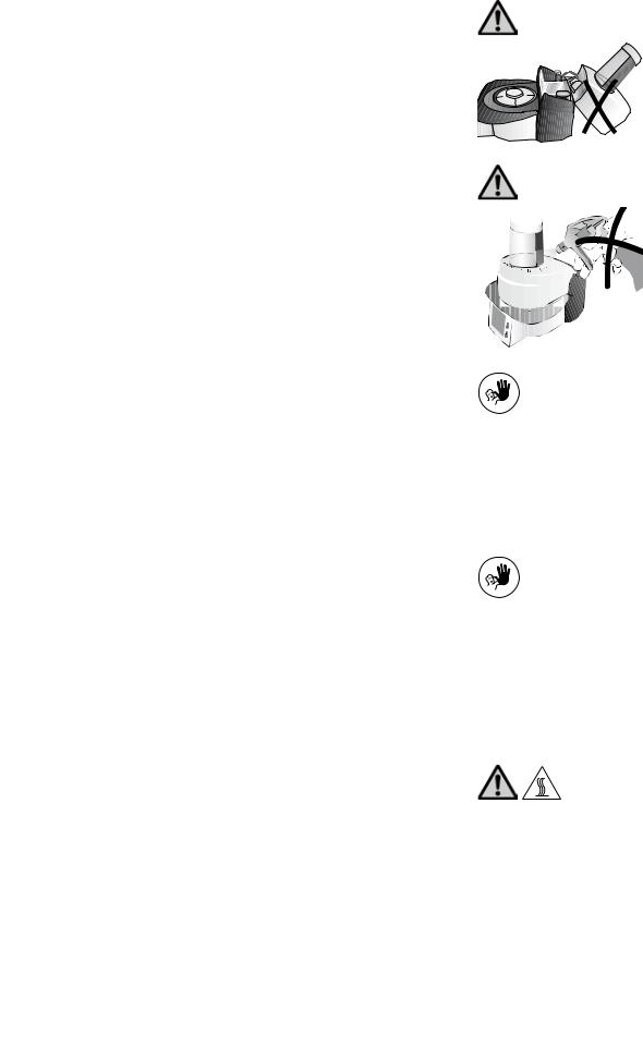
2.1.1
Risks and dangers
The furnace head should not be removed from the furnace base as long as the furnace head is connected by means of the heater cable.
2.1.2
Risks and dangers
Make sure that no liquids or other foreign objects enter the furnace.
2.1.3
Contraindication
Firing trays must not be placed in the area surrounding the firing table, since this will obstruct the closing of the furnace head.
2.1.4
Contraindication
Foreign objects must not be placed on the furnace head or air vents. Make sure that no liquids or other foreign objects enter the air vents, since this may result in an electrical shock.
2.1.5
Risks and dangers, burn hazard
Never place objects in the firing chamber by hand, since there is a burn hazard. Always use the tongs (accessories) supplied for this purpose. Never touch the hot surface of the furnace head, as there is a burn hazard. Please also refer to the warnings on the furnace.
9
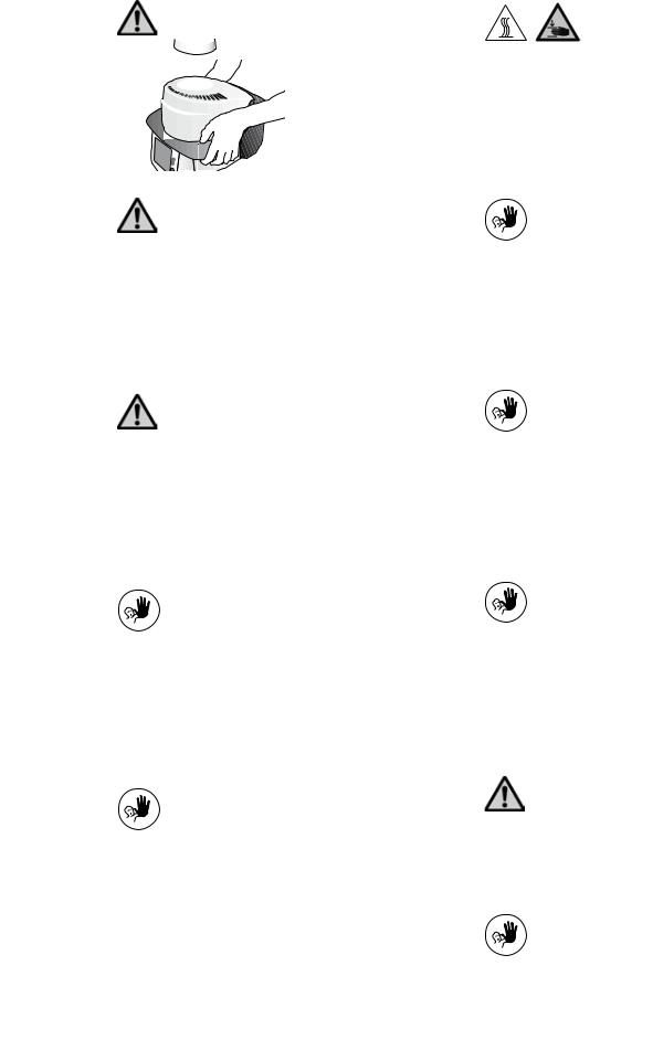
2.1.6 |
2.1.11 |
Risks and dangers
Do not carry the furnace by the cooling tray.
Risk of crushing and burn hazard
Never reach under the furnace head with the hand or other parts of the body during operation, since there is a risk of crushing and a burn hazard.
2.1.7 |
2.1.12 |
Risks and dangers |
Contraindication |
Do not carry the furnace head by the cables, since the cables and
connections may be damaged.
Do not insert any foreign objects into the air vents. There is a risk of electrical shock.
2.1.8 |
2.1.13 |
|
|
Risks and dangers |
Contraindication |
The furnace head is equipped with an electric drive and must be operated by means of the electronic controls. Never open the furnace head by hand, since the mechanism will be damaged.
This product contains ceramic fibres and may release fibre dust. Do not use compressed air, or blow on the furnace thus distributing the dust in the environment and observe the additional notes on page 11.
2.1.9
Contraindication
Never use the furnace without a firing table.
2.1.10
Contraindication
Do not touch the thermocouple or the quartz tube in the firing chamber. Avoid contact with the skin (grease contamination), as the parts may be damaged.
2.1.14
Contraindication
Do not cool the hot investment ring on the cooling tray. Use only the cooling grid for that purpose.
2.1.15
Risks and dangers
The furnace must not be operated if the quartz tube or the insulation in the firing chamber is damaged. There is a risk of electric shock upon contact with the heating wire.
Avoid any damage of the insulation by contact with the investment tongs or firing tongs. Make sure to keep the firing plate for the investment ring clean.
2.1.16
Contraindication
Only use original ring bases from Ivoclar Vivadent. Observe the maximum height (57 mm) and diameter (35 mm, 50 mm and 65 mm) of the investment ring.
10
2.2 Health and safety instructions
This furnace has been designed according to EN 61010-1 and has been shipped from the manufacturer in excellent condition as far as safety regulations are concerned. To maintain this condition and to ensure risk-free operation, the user must observe the notes and warnings contained in these Operating Instructions.
–Place furnace on a fire-proof table (observe local regulations, e.g. distance to combustible substances or objects, etc.).
–Always keep the air vents at the rear of the furnace free from obstruction.
–Do not touch any parts that become hot during operation of the furnace. There is a burn hazard.
–Clean furnace only with a dry or slightly moist cloth. Do not use any solvents. Disconnect power before cleaning.
–Use original packaging for transportation purposes.
–The furnace must be cool before it is packed for transportation.
–The user must especially become familiar with the warnings and operating conditions to prevent injury to personnel or damage to materials. The manufacturer is not responsible for damage resulting from misuse or failure to observe the Operating Instructions. Warranty claims cannot be accepted in such cases.
–Before switching on the furnace, make sure that the voltage indicated on the rating plate complies with your local power supply.
–The power socket must be equipped with a residual current circuit breaker.
–The furnace must be plugged into a socket with protected contacts.
–Before calibration, maintenance, repair, or exchange of parts, the power must be disconnected if the furnace is to be opened.
–If calibration, maintenance, or repair has to be carried out with the power connected and the furnace open, only qualified personnel, who are familiar with the risks and dangers, may perform these procedures.
–After maintenance, the required safety tests (high voltage resistance, protective conductor, etc.) have to be carried out.
–Ensure that only fuses of the indicated type and rated current are used.
–If it is assumed that safe operation is no longer possible, the power must be disconnected to avoid accidental operation. Safe operation is no longer possible if
–the furnace is visibly damaged
–the furnace does not work
–the furnace has been stored under unfavourable conditions over an extended period of time
–Use only original spare parts.
–The temperature range for faultless operation is +5 °C to +40 °C (41 °F to 104 °F).
–If the furnace has been stored at very low temperatures or high atmospheric humidity, the head has to be opened and the unit dried or left to adjust to room temperature for approx. 1 hour (do not connect the power yet).
–The furnace has been tested for use at altitudes of up to 2000 m above sea level.
–The furnace may only be used indoors.
–Do not run the furnace via an extension cord.
–When placing and removing the investment ring, make sure not to hit the insulation of the firing chamber.
–There is a burn hazard at the cooling tray if the furnace is continuously operated in the press mode (stand-by = 700 °C).
Any disruption of the protective conductor either inside or outside the furnace or any loosening of the protective conductor connection may lead to danger for the user in case of a malfunction. Deliberate interruptions are not tolerated. Materials developing harmful gases must not be fired.
Warnings regarding the removal of the heating muffle
This product contains ceramic fibres and may release fibre dust. Fibre dust has proved to be carcinogenic in animal experiments.
The heating muffle must only be disassembled by a certified After Sales Service Centre. Information regarding the Safety Data Sheet is also available from your After Sales Service Centre.
Warning
The insulation on this product contains refractory ceramic fibres (RCF) which pose a possible cancer hazard, if agitated and inhaled. May be irritating to the skin, eyes or respiratory tract if insulation is cracked or corrupted.
California Proposition 65
Warning: ”This product contains Refractory Ceramic Fibres, a substance known to the State of California to cause cancer.”
Disposal:
The furnaces must not be disposed in the normal domestic waste. Please correctly dispose of old furnaces according to the corresponding EU council directive. Information on the correct disposal may also be found on your local Ivoclar Vivadent homepage.
11

3. Product Description
3.1 Components
The Programat EP 3000/G2 comprises the following components:
–Furnace base with electronic controls
–Furnace head with firing chamber and press drive
–Firing plate
–Cooling tray
–Power cord and hose for vacuum pump
–Vacuum pump (accessories)
3.2 Hazardous areas and safety equipment
Description of the hazardous areas of the furnace:
Hazardous area |
Type of risk |
|
|
Firing chamber |
Risk of burning |
|
|
Opening/closing mechanism |
Risk of crushing |
|
|
Electrical components |
Risk of electrical shock |
|
|
Description of the safety equipment of the furnace: |
|
|
|
Safety equipment |
Protective effect |
|
|
Protective conductor |
Protection from electrical shock |
|
|
Electrical fuses |
Protection from electrical shock |
|
|
Housing and covers |
Protection from electrical shock, burn hazard and |
|
crushing |
|
|
3.3 Functional description
The firing/pressing chamber may be heated up to max. 1200 °C (2192 °F) by means of a heating element . Furthermore, the firing chamber has been designed in such a way that a vacuum may be created with a vacuum pump. The presssure for the press procedure is generated by a press drive. The firing/pressing programs are controlled with the corresponding electronic controls and software.Moreover, the set and actual temperatures are continuously compared.
3.4 Accessories
(not part of the delivery form)
–Automatic Temperature Checking Set 2 (ATK 2)
–Programat Accessories Set 2 (Programat firing trays, Silicone Nitride Firing Tray “K”, firing tongs, Automatic Temperature Checking Set 2)
–Vacuum pump
12
 Loading...