


 Loading...
HP Designjet L65500 Printer & HP Scitex LX Printer family
Installation guide (third edition)
Legal notices
© 2009 Hewlett-Packard Development
Company, L.P.
The information contained herein is subject to change without notice.
The only warranties for HP Products and services are set forth in the express warranty statement accompanying such products and services. Nothing herein should be construed as constituting an additional warranty. HP shall not be liable for technical or editorial errors or omissions contained herein.
Trademarks
Microsoft® and Windows Vista® are U.S. registered trademarks of Microsoft Corporation.

Table of contents
1 |
Safety precautions |
|
|
General safety guidelines ..................................................................................................................... |
1 |
|
Electric shock hazard ........................................................................................................... |
1 |
|
Heat hazard ......................................................................................................................... |
2 |
|
Fire hazard ........................................................................................................................... |
2 |
|
Mechanical hazard ............................................................................................................... |
2 |
|
Heavy substrate hazard ....................................................................................................... |
3 |
|
Ink handling ......................................................................................................................... |
3 |
|
Warning and Cautions ......................................................................................................... |
3 |
|
Warning labels ..................................................................................................................... |
3 |
|
Emergency stop buttons ...................................................................................................... |
5 |
2 |
Introduction |
|
|
Installation guide overview ................................................................................................................... |
6 |
|
Manpower required .............................................................................................................................. |
6 |
|
Tools required for installation ............................................................................................................... |
6 |
|
Inbox content ........................................................................................................................................ |
7 |
3 Receive the shipment |
|
|
|
Unload the crate ................................................................................................................................... |
9 |
|
Move the printer over ramps .............................................................................................................. |
10 |
|
Remove the crate packaging .............................................................................................................. |
10 |
|
Remove the printer from the pallet ..................................................................................................... |
11 |
|
Lift the printer to a second floor using a crane ................................................................................... |
13 |
4 |
Set up the printer in the final position |
|
|
How to push the printer ...................................................................................................................... |
15 |
|
Choose the final position .................................................................................................................... |
15 |
|
Remove additional packaging ............................................................................................................ |
17 |
|
Lower the feet ..................................................................................................................................... |
22 |
5 Connect the power cables |
|
|
|
Requirements ..................................................................................................................................... |
23 |
ENWW |
iii |
|
Tri-phase AC Power Cord .................................................................................................................. |
23 |
|
Protective Earth conductors (grounding) ............................................................................................ |
26 |
6 |
Configure the electrical system |
|
|
Install the fuses and power jumper ..................................................................................................... |
27 |
|
Choose delta or star (Y) configuration ................................................................................................ |
29 |
|
Check resistances .............................................................................................................................. |
31 |
|
Check connections ............................................................................................................................. |
31 |
|
Connect mains power ......................................................................................................................... |
32 |
|
Power on the printer ........................................................................................................................... |
32 |
7 Purge the ink system |
|
|
8 |
Prepare the printer |
|
|
Install the printhead cleaning roll and aerosol filters .......................................................................... |
50 |
|
Install the computer, monitor, LAN switch, tray, keyboard and mouse .............................................. |
53 |
|
Create a shared folder on the HP Internal Print Server computer ...................................................... |
55 |
|
Configure the printer’s IP address ...................................................................................................... |
58 |
9 |
Prepare for printing |
|
|
Install the printheads .......................................................................................................................... |
59 |
|
Callme@HP Setup Process .............................................................................................................. |
62 |
|
Antivirus Registration ........................................................................................................................ |
63 |
|
Web Cam Installation ......................................................................................................................... |
63 |
|
Load a substrate ................................................................................................................................. |
63 |
|
Connect the air supply ........................................................................................................................ |
63 |
|
Configure the RIP ............................................................................................................................... |
64 |
|
Install the covers ................................................................................................................................ |
66 |
|
Print the HP test images ..................................................................................................................... |
68 |
Appendix A Prepare the HP Internal Print Server (Japan and Russia only) |
|
|
Appendix B Manually configure the printer’s IP address |
|
|
Appendix C Change the Windows Vista language |
|
|
iv |
ENWW |

1 Safety precautions
Before installing the printer, read the following safety precautions.
General safety guidelines
●No operator serviceable parts inside. Refer servicing to qualified service personnel.
●Turn off the printer, using both Branch Circuit Breakers located in the building's Power Distribution Unit (PDU), and call your service representative in any of the following cases:
◦The power cord is damaged.
◦Liquid has entered the printer.
◦There is smoke or an unusual smell coming from the printer.
◦The printer has been dropped or the drying or curing module damaged.
◦The printer's built-in Residual Current Circuit Breaker (Ground Fault Circuit Interrupter) has repeatedly tripped.
◦Fuses have blown.
◦The printer is not operating normally.
●Turn off the printer using both Branch Circuit Breakers in either of the following cases:
◦During a thunderstorm
◦During a power failure
Electric shock hazard
 WARNING! The internal circuits and drying and curing modules operate at hazardous voltages capable of causing death or serious personal injury.
Turn off the printer using both Branch Circuit Breakers located in the building's Power Distribution Unit (PDU) before servicing the printer. The printer must be connected to earthed mains outlets only.
To avoid the risk of electric shock, do not attempt the following actions:
●Do not attempt to dismantle the drying and curing modules or the electrical control cabinet.
●Do not remove or open any other closed system covers or plugs.
●Do not insert objects through slots in the printer.
ENWW |
General safety guidelines 1 |

 NOTE: A blown fuse may indicate malfunctioning electrical circuits within the system. Call your service representative, and do not attempt to replace the fuse yourself.
Heat hazard
The drying and curing subsystems of the printer operate at high temperatures and can cause burns if touched. To avoid personal injury, take the following precautions.
●Do not touch the internal enclosures of the printer's drying and curing modules.
●Take special care when accessing the substrate path.
Fire hazard
The drying and curing subsystems of the printer operate at high temperatures. Call your service representative if the printer's built-in Residual Current Circuit Breaker (Ground Fault Circuit Interrupter) is repeatedly tripped.
To avoid the risk of fire, take the following precautions.
●Do not insert objects through slots in the printer.
●Take care not to spill liquid on the printer.
●Do not use aerosol products that contain flammable gases inside or around the printer.
●Do not block or cover the openings of the printer.
●Do not attempt to dismantle the drying or curing module, or the electrical control cabinet.
●Load substrates that can be used at an operating temperature of up to 125°C (257°F), and have auto-ignition temperatures above 250°C (482°F).
Mechanical hazard
The printer has moving parts that can cause injury. To avoid personal injury, take the following precautions when working close to the printer.
●Keep your clothing and all parts of your body away from the printer's moving parts.
●Avoid wearing necklaces, bracelets and other hanging objects.
●If your hair is long, try to secure it so that it will not fall into the printer.
●Take care that sleeves or gloves do not get caught in the printer's moving parts.
●Avoid standing close to the fans, which could cause injury and could also affect print quality (by obstructing the air flow).
●Do not touch gears or moving rolls during printing.
2 Chapter 1 Safety precautions |
ENWW |

Heavy substrate hazard
Special care must be taken to avoid personal injury when handling heavy substrates.
●Handling heavy substrate rolls always requires at least two people. Care must be taken to avoid back strain and/or injury.
●Always use a forklift, pallet truck or other handling equipment to lift substrates.
●Always wear personal protective equipment including boots and gloves.
Ink handling
Your printer does not use solvent inks and does not have the traditional problems associated with them. However, HP recommends that you wear gloves when handling ink cartridges or printhead cleaner rolls.
Warning and Cautions
The following symbols are used in this manual to ensure the proper use of the printer and to prevent the printer from being damaged. Follow the instructions marked with these symbols.
 WARNING! Failure to follow the guidelines marked with this symbol could result in serious personal injury or death.
 CAUTION: Failure to follow the guidelines marked with this symbol could result in minor personal injury or damage to the product.
Warning labels
Label |
Explanation |
|
|
|
Current leakage may exceed 3.5 mA. |
The printer can be connected to power supplies at different voltages.
Identifies the Protective Earth (PE) terminal. It is located inside the electrical control cabinet.
ENWW |
General safety guidelines 3 |

Label |
Explanation |
|
|
|
Electric shock hazard. The printer has two mains supplies. |
|
There are no operator-serviceable parts inside the printer. In |
|
case of operation of the fuse, parts of the printer that remain |
|
energized may represent a hazard during servicing. Refer |
|
servicing to qualified service personnel. Turn off the printer |
|
using both Branch Circuit Breakers located in the building's |
|
Power Distribution Unit (PDU) before servicing. See |
|
installation instructions before connecting to the supply. |
|
|
|
Danger of electric shock. In case of operation of the fuse, parts |
|
of the printer that remain energized may represent a hazard |
|
during servicing. Therefore, ensure that the printer is |
|
completely turned off before servicing. |
Risk of burns. Do not touch the internal enclosures of the printer's drying and curing modules.
You are recommended to wear gloves when handling ink cartridges, printhead cleaning cartridges and the printhead cleaning container.
When substrate has been loaded, the carriage descends into its normal position, and could crush your hand or anything else left underneath it.
Danger that your hands may become trapped between gearwheels
When the printer is printing, the printhead carriage travels back and forth across the substrate.
Beware of this moving part.
4 Chapter 1 Safety precautions |
ENWW |

Emergency stop buttons
There are four emergency stop buttons distributed around the printer. If an emergency occurs, simply push one of the emergency stop buttons to stop all printing processes. A system error message is displayed on the front panel, and the fans turn at maximum speed. Ensure that all emergency stop buttons are released before restarting the printer.
ENWW |
General safety guidelines 5 |

2 Introduction
Installation guide overview
This installation guide provides you with step by step procedures for the installation process. This guide is organized in chronological order and should be followed from beginning to end.
Manpower required
Installation of your HP Designjet L65500 & HP Scitex LX600/LX800 requires the following manpower:
●HP Installation Specialist
●Customer
●Certified electrician
●Moving specialist
Tools required for installation
TIP: Without a heavy-duty electric screwdriver, it could take up to two hours just to disassemble the crate.
Installation of your HP Designjet L65500 HP Scitex LX600/LX800 requires the following tools:
●Step ladder
●Cutting pliers
●Cutter
●Heavy-duty electric screwdriver with two batteries
●Phillips screwdrivers
●T8, T10, T15, T20, T25 and T30 torx screwdrivers
●Long torx extension pins that have a diameter of approximately 2–3 mm and are more than 15 cm in length to be able to access all screws
●Two Flathead screwdrivers (two sizes)
●Socket wrench, extension and 17 mm socket
●7 mm, 15 mm and two 30 mm open-end wrenches
6 Chapter 2 Introduction |
ENWW |
Inbox content
 NOTE: The shipment items should be verified during installation.
NOTE: Ink cartridges do not come with the printer and should have been ordered by the customer prior to installation. Make sure that the ink cartridges are available.
The shipment should include the following items:
●The HP Printer
●Documentation CD including the Legal Information, the Maintenance and Troubleshooting Guide and the User's Guide
●Maintenance and troubleshooting guide
●Operating System Recovery CD
●Pneumatic gun
●L65500 only: 1 substrate roll
●2 spindles (the front spindle is mounted on the printer with ties, the rear spindle is attached to the pallet)
●1 empty substrate core
●L65500 only:
◦HP 786 Yellow/Magenta Designjet Printhead
◦HP 786 Cyan/Black Designjet Printhead
◦HP 786 Lt Magenta/ Lt Cyan Designjet Printhead
●LX600/LX800 only:
◦HP 786 Yellow/Magenta Scitex Printhead
◦HP 786 Cyan/Black Scitex Printhead
◦HP 786 Lt Magenta/ Lt Cyan Scitex Printhead
●LX800 only: Ink Collector Kit
◦8 collector plates (in one box)
◦2 Diverters
●LX800 only: Dual Roll Kit
◦2 spindles with differential
◦Edge Holders
◦Allen Keys 4,6
●1 HP Internal Print Server computer (includes keyboard, mouse and power cord)
●1 LAN switch (includes power cord)
ENWW |
Inbox content 7 |

●1 Flat screen monitor (includes power cord)
●Ethernet cables (computer to LAN switch)
●Keyboard Tray
●Sliding Door Handle
●Covers (with screws)
●Product name label
●Fuse and cable kit
◦6 fuses, 1 extra fuse
◦Set of power jumpers includes 200V, 240/230V, 220V, 127V/120V and 115V/100V/110V
●Two electrical cabinet keys
●Printer Cleaning Kit
●Maintenance Kit
◦2 aerosol filters
◦1 printhead cleaner roll
●Purge kit
◦7 syringes and needles (extra syringe/needle set is included)
◦6 purge bags
◦1 purger quick connector (already installed)
◦4 air purgers (extra air purger is included)
◦Protective gloves and cloth
●12 intermediate tanks and labels
 NOTE: The Russian printer configuration includes two 2 MB memory cards.
8 Chapter 2 Introduction |
ENWW |
3 Receive the shipment
Unload the crate
Manpower |
Tools |
Time |
|
|
|
2 persons |
Forklift, skates |
15 minutes |
|
|
|
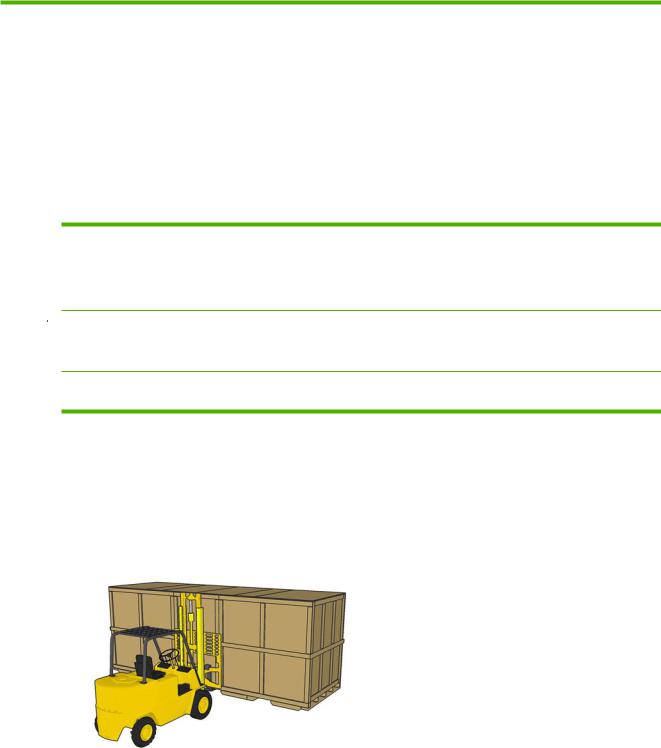
 WARNING! The crate must be lifted with a forklift from the front side of the crate. The front side of the crate will be marked Front. This is important because of the weight distribution inside the crate.
WARNING! Do not stand on top of the crate.
Shown below are the recommended specifications of the forklift that should be used to move the crate.
|
Weight |
Fork Length |
Distance between forks |
|
|
|
|
Forklift for L65500/LX600 |
2721 kg (5999 lb) |
2 m (78.74 in) |
800 mm (31.5 in) |
|
|
|
|
Forklift for LX800 |
3500 kg (7716 lb) |
2 m (78.74 in) |
800 mm (31.5 in) |
|
|
|
|
1.To move the crate with a forklift, insert the forks in the designated slots on the crate. Always lift the crate from the front and center.
ENWW |
Unload the crate 9 |
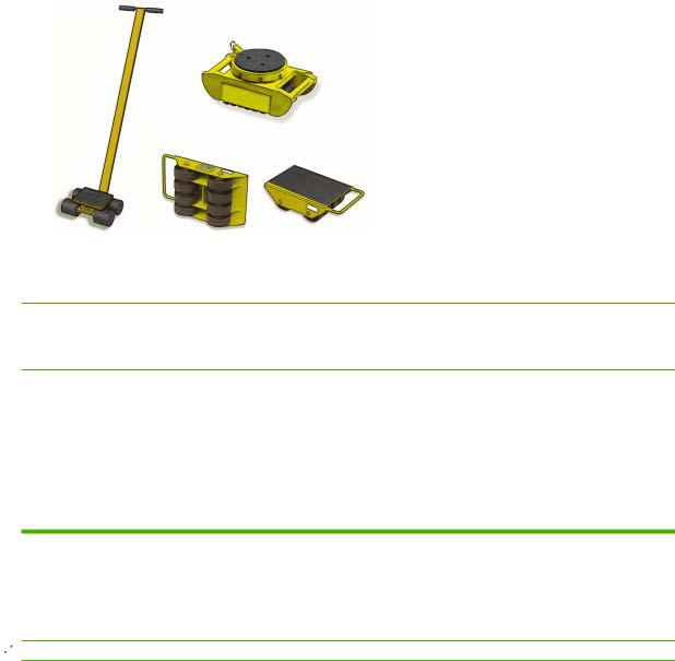
2.You can also use skates to maneuver the crate around tight corners or to move the crate laterally.
Move the printer over ramps
 WARNING! Do not exceed the maximum incline if you must move the printer up or down a ramp. Failure to respect the maximum incline could damage the printer.
 CAUTION: Slopes steeper than 5% may cause serious damage to the printer.
Once the crate packaging has been removed from the printer, the maximum incline of a ramp used to move the printer is 5%.
If you must move the printer over a ramp that exceeds the maximum incline (5%), do not remove the printer from the pallet. The pallet will help prevent damage to the printer.
Remove the crate packaging
Manpower |
Tools |
Time |
|
|
|
2 persons |
M17 socket wrench, Phillips screwdriver, |
40 minutes |
|
pliers, ladder |
|
|
|
|
 NOTE: Approximately 16 bolts and 100 Phillips screws secure the crate.
In some cases, it may be necessary to leave the printer inside the crate packaging to go up ramps or make second story deliveries. Plan accordingly.
1.Beginning with the top, left corners, remove the Phillips screws securing the top panels and remove them.
10 Chapter 3 Receive the shipment |
ENWW |
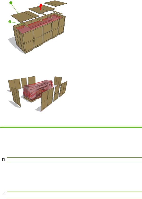
2.Remove the four support beams. Be careful that the support beams do not fall into the crate.
3.Use a Phillips screwdriver to remove the remaining screws that secure the side panels.
4.Carefully remove the panels and open the plastic bag surrounding the printer and free it from the printer.
Remove the printer from the pallet
Manpower |
Tools |
Time |
|
|
|
1 person |
Two M30 sockets, M17 socket wrench, |
10 minutes |
|
cutter, forklift |
|
|
|
|
|
|
|
1.Remove the 8 Phillips screws that secure the items box and remove it.


 NOTE: The starter kit weighs 60 kg. Two people are needed to lift it.
2.Remove the PC box and the disassembled covers.
3.LX800 only: Remove the Ink Collector Ink.
4.Use the 17 mm socket wrench to remove the spindle.
5.Lift the spindle away from the pallet.
 NOTE: If you must lift the printer with a crane or perform difficult maneuvers, use tape to prevent the door from opening accidentally.
ENWW |
Remove the printer from the pallet 11 |
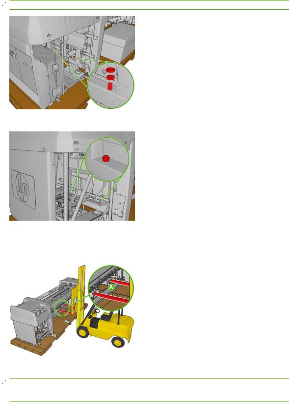
6.Remove the two 30 mm nuts attaching the left side of the printer to the pallet.
 NOTE: Use a second M30 wrench to hold the second 30 mm nut in place.
7.Remove the two 30 mm nuts attaching the right side of the printer to the pallet.
8.Make sure that the feet are up and the sliding door is secured with the tape used for transportation.
9.Locate the forklift guides underneath the printer and make sure that the forks on the forklift are spaced 80 cm apart (A).
10. Carefully lift the printer, move it away from the pallet and set it on the floor.
 NOTE: The printer weighs more on the right side than the left side. Make sure that it does not tilt toward the right hand side when you lift the printer. Make sure you lift the printer high enough so the screws that attach the printer to the pallet do not touch the printer.
12 Chapter 3 Receive the shipment |
ENWW |
Lift the printer to a second floor using a crane
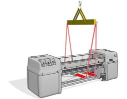
At this point, normally you would push the printer to the final location. However, if you need to make a second floor installation, a crane will be needed to lift the printer. The same guides used to lift the printer with a forklift should be used to lift the printer with a crane. To do so, lifting bars must be inserted into the forklift guides. The lifting cables can either be attached to a spreader beam or directly to the crane.
In some cases, the printer can be lifted by the crane without removing the crate. If the unloading area for the crate has enough space to disassemble the crate safely, this situation is ideal.
 NOTE: The lifting bars, spreader beam and any other crane attachment must be supplied by the customer. For the exact specifications of the crane attachments, see the Site Preparation Guide.
 WARNING! When lifting the printer with a crane, extra caution should be taken to ensure that the cables do not apply pressure to the center covers or carriage beam.
 CAUTION: The printer weight is not evenly distributed, and it may tilt to the right side.
 NOTE: The printer will bend as you lift it.
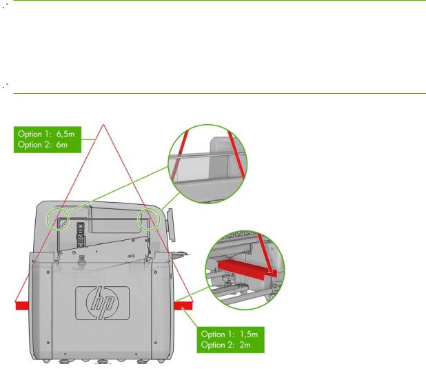
The following graphic illustrates how to lift the printer using lifting bars.
If you use a spreader beam to lift the printer, make sure that the spreader beam and lifting bars are wide enough so the lifting cables do not touch the center covers or carriage beam. The following graphic illustrates how to lift the printer with a spreader beam.
ENWW |
Lift the printer to a second floor using a crane 13 |
14 Chapter 3 Receive the shipment |
ENWW |
4 Set up the printer in the final position
How to push the printer
Manpower |
Time |
|
|
2 persons |
Varies |
|
|
 NOTE: Do not remove the ISM or electrical cabinet straps until the printer is in the final position. When you set the printer on the floor, the printer wheels allow you to easily roll the printer.
Only push the printer from the outside corners of the top covers on either side of the printer.
Choose the final position
Your HP Designjet L65500 printer requires enough space to perform the following tasks:
●Use the HP Internal Print Server
●Replace a substrate roll
●Service the printer or replace printer components
●Ensure the printer is well ventilated
The printer has the following dimensions:
ENWW |
How to push the printer 15 |

Printer |
Length |
Width |
Height |
|
|
|
|
HP Designjet L65500 |
5 m (16 ft, 5 inches) |
1.6 m (5 ft, 3 inches) |
1.8 m (5 ft, 11 inches) |
|
|
|
|
HP Designjet LX600 |
5 m (16 ft, 5 inches |
1.6 m (5 ft, 3 inches) |
1.6 m (5 ft, 3 inches) |
|
|
|
|
HP Designjet LX800 |
5.7 m (18 ft, 11 inches) |
1.6 m (5 feet, 3 inches) |
1.6 m (5 feet, 3 inches) |
|
|
|
|
The following table and illustration shows the minimum space required for the printer.
Measurement
AL65500/LX600: 7m (23ft)
LX800: 8m (26ft 3 in)
B1.5 m (5ft)
C0.6 m (2 ft) minimum
D4 m (13 ft, 2 in)
E1.5 m (5 ft)
F1.5 m (5 ft)
 WARNING! The zone surrounding the HP Designjet L65500 printer should be considered a restricted access area and signaled accordingly. Only trained personnel should be operating within this area.
16 Chapter 4 Set up the printer in the final position |
ENWW |
Remove additional packaging
Manpower |
Tools |
Time |
|
|
|
1 person |
Cutting Pliers, Allen keys, T20 and T25 |
15 minutes |
|
screwdrivers |
|
|
|
|
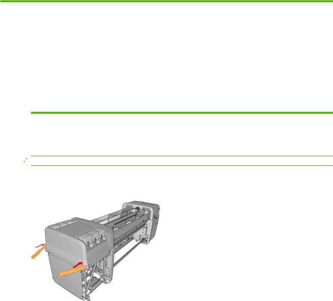
1.From the back, remove the electrical cabinet straps and foams from the printer.
2.Remove the straps from the sliding doors.
 NOTE: The keys to the electrical cabinet are located on top of the cabinet.
ENWW |
Remove additional packaging 17 |

3.Remove the eight T20 screws attaching the scan path assembly to the frame. Use a screwdriver extension for easier screw access.
 WARNING! Failure to remove the screws attaching the scan path assembly to the frame could seriously damage the printer.
 NOTE: The screws located at the back, are less accessible and may require a longer screwdriver.
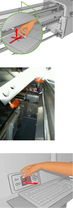
4.Remove tape from the window and open the carriage access door, remove the T30 screw securing the carriage.
18 Chapter 4 Set up the printer in the final position |
ENWW |
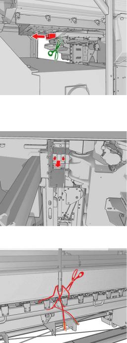
5.Remove the tie and 2 foam pieces that secure the service station.
6.Remove the four foam pieces that secure the top cover.
7.Remove the two T20 screws securing the printhead cleaning assembly.
8.Remove the substrate pressure handle straps (pinches).
9.Remove the plastic ties securing the diverter.
ENWW |
Remove additional packaging 19 |
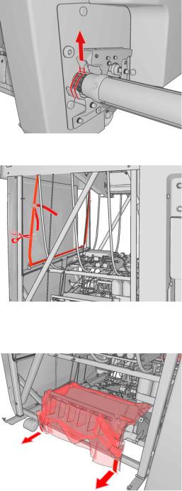
10. Remove the plastic tie securing the spindle and the tape covering the air valve.
11. Remove the ink system compartment strap from the printer.
12.Remove the plastic coverings from the ink cartridge connectors.
13.Remove the intermediate tank plastic bags, foams and straps.
14.Remove the plastic ties securing the tri-phase and single-phase power cables.
15.Remove any other plastic ties that you can see inside the printer.
20 Chapter 4 Set up the printer in the final position |
ENWW |
16. Remove the tape covering the OMAS window on the print platen.
17. Remove the tapes covering the temperature sensors.
18. Remove the plastic covering from the carriage access door , front panel and central cover.
19.Remove tape from the Curing Plate.
20.Remove foam pieces from the left and right.
21.Remove foam pieces from the rear beam structure.
ENWW |
Remove additional packaging 21 |
22.Remove 4 plastic ties from the left side cover.
23.Remove plastic ties from the top covers.
Lower the feet
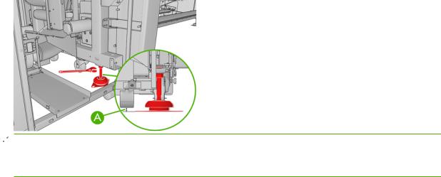
1.Use a 30 mm wrench to unlock the nut at the top of the foot.
2.Rotate the nut manually down the bolt. Leave about 0.8 inches (2 cm) of clearance at the bottom between nut and foot.
3.Use a 15 mm wrench to rotate the foot downwards. Use the flat faces at the bottom of the bolt to fit the wrench.
4.Lower the foot as far as the bolt allows.
5.Once the wheels are 15 mm (A) off the ground, tighten the 30 mm locking nut against the printer structure
 NOTE: The right side of the printer is heavier than the left side. Therefore, the feet on the right side will be more difficult to lower.
NOTE: The position of the feet must be parallel with the spindle.
22 Chapter 4 Set up the printer in the final position |
ENWW |
Loading...