


1 Printer systems
Printer Systems
• |
Electrical system ..................................................................................................... |
4 |
||
|
• |
Ecabinet......................................................................................................... |
5 |
|
|
• |
E-Box |
........................................................................................................... |
19 |
|
|
• |
ECabinet Circuit Diagrams ..................................................................... |
10 |
|
• PCA Boards ..........................................................................and connections |
20 |
||
|
|
• ...................................................................................... |
Formatter PCA |
20 |
|
|
• ..................................................................................... |
Hard disc drive |
20 |
|
|
• ........................................................ |
Upper and Lower Engine PCI Board |
20 |
|
|
• ................................................................................... |
Printmech Board |
21 |
|
|
• ...................................................... |
Main Interconnect Board connections |
22 |
• |
Substrate path ..................................................................................................... |
28 |
||
• |
Ink System ........................................................................................................... |
|
39 |
|
• |
Scan Axis ........................................................................................................... |
|
45 |
|
• |
Carriage............................................................................................................. |
|
57 |
|
• |
Printhead Cleaning ....................................................................................System |
61 |
||
• |
Heating and .............................................................................................Curing |
66 |
||
• |
User Interface ...................................................................................................... |
74 |
||
Printer systems |
3 |

Printer systems
Electrical system
The electrical system is primarily housed in the electrical cabinet, inside this is the electronics box.
Electronics overview diagram
The following diagram explains the connections between components and electronic boards, the voltage, or the type of data line.
4 |
Printer systems |
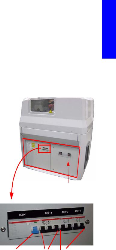
Ecabinet
The ECabinet located on the right side of the printer and is the enclosure where the main electronics (Electronic Control System, E-box) and all the power electrical components of the printer are located. The system if fed via two power lines, one single phase line and another tri-phase line see the Installation Guide and Site Preparation guide for specifications.
The E-Cabinet responsible for distributing all the power lines to the functional areas, it includes the active power elements of the heating and curing subsystem. It also performs safety cut-outs when any of the four emergency stops are pushed
Some of the components inside the e-cabinet are independent units isolated from the electronics therefore diagnosing any issues via Firmware is not possible.
To diagnose most electrical issues, voltage and continuity checks are required from the Service Engineer by using multi-meter tools (Voltmeter, Amp meter, resistor meter, continuity checks)
Components
The Ecabinet contains the following components:
•The Ebox
•Secondary 24v Power supply
•Secondary 42v Power supply
•Circuit breakers & Residual Current Circuit breaker (RCCB)
•Contactor (Heating and Curing)
•Fuses (Heating and Curing)
•E-Box system (which includes a main power supply delivering ATX tensions and also 24V and 42V)
• Safety relay
•Fan
•Scan Axis break resistor
• |
Vacuum system transformer (110v) |
|
The ECabinet |
• |
Main switch |
|
|
• |
Power Enable button |
RCD-1 |
ACB-3 ACB-2 ACB-1 |
• Light indication for Phases
• 3 Phase Line filter
• 1 Phase Line filter
Printer systems
Residual |
3 phase |
Single phase |
Current |
Circuit |
Circuit breaker |
Circuit |
breaker |
|
Breaker |
|
|
(RCCB) |
|
|
Printer systems |
5 |

Printer systems
Inside the ECabinet (1 of 2)
|
|
|
|
|
|
ECabinet |
Secondary 24v supply |
Line filter 42v |
Safety Relay |
Secondary 42v supply |
|
line +resistors |
|||||
|
|||||
fan |
|
|
|
|
|
|
|
|
|
Heating |
|
1 Phase |
|
||
and |
|
|
|
Line filter |
|
Curing |
|
|
|
|
|
Power |
|
|
Modules |
|
|
|
|
|
(power |
|
|
lines are |
|
|
thicker in |
|
Roll to Free |
the LX800) |
|
|
|
Floor |
|
|
|
|
|
|
control |
|
|
system |
|
|
LX800 |
Contactor |
Terminal |
Ebox |
|
RM 3 Phase |
Blocks |
||
|
Inside the ECabinet (2 of 2)
Power fuses heating/
Curing
|
|
|
|
|
|
3 Phase line filter |
|
|
Vacuum |
Main switch |
|
|
transformer 110v |
||
|
|
||
|
|
|
Light indicator |
|
|
|
for phases |
|
|
|
|
Fuse block (1A, 2A, 4A
Vacuum power On
Power enable button
6 |
Printer systems |

Ecabinet Fuse blocks
Fuse Application
•Fuses: 1,2,3 (1A) Indicator Lamps
•Fuses 6, 7 (1A): PID controllers
•Fuse 8 (2A): Phase 110 from Trafo to Pump
•Fuse 9 (2A): Neutral 0V from Trafo to Pump
•Fuse 10 (4A): protects 110V transformer
•Fuse 11 (2A): 24V from Main interconnect to e-cabinet
Printer systems
Functionality
1.The E-Cabinet is the power distribution centre for the whole printer
It is the central point where both input power lines (Single and tri-phase) are connected and then distributed to the different power components.
Single Phase components powered through ACB1
•Heating Controller Module
•Curing Controller Module
•Secondary 42V power supply (SAX motor, Media Path Motors)
•Secondary 24V power supply (Curing Fans)
•Vacuum Fan
•E-Box
Single Phase components powered through ACB2
•Printer PC (Windows, IPS)
•Printer Monitor
•Printer Switch
Tri-Phase components powered through ACB3 and RCCB
•Heating and Curing Power modules – Heating and curing lamps
-Contains the Ebox
-Emergency stop mechanism for the machine.
-Heating and curing control and power distribution.
Printer systems |
7 |

Printer systems
ECabinet electrical overview
42v Secondary Power Supply, Power distribution diagram
8 |
Printer systems |

Functionality interlinked between diagrams
3 phase power supplied to the Heating and curing Modules through the power fuse blocks (FH4, FH5):
|
|
|
|
|
|
|
|
|
|
|
|
|
|
|
|
|
|
|
|
Lamps |
|
|
|
Main |
|
Line |
|
|
Circuit |
|
|
Contactor |
|
|
Power |
|
Power |
|
Heating |
||||||
|
Switch |
|
Filter |
|
|
Breaker |
|
|
KM SW-1 |
|
|
Fuses |
|
Module |
|
|
Configuration Block |
|
|
|
Heating |
|
|
|
|
|
|
|
|
|
|
|
|
||||||||||||
|
|
|
|
|
|
|
|
|
|
|
|
Heating |
|
Heating |
|
|
(star/triangle) |
|
|
|
|
|
|
|
|
|
|
|
|
|
|
|
|
|
|
|
|
|
|
||||||
|
|
|
|
|
|
|
|
|
|
|
|
|
|
|
|
|||||||
|
|
|
|
|
|
|
|
|
|
|
|
|
|
|
|
|
|
|
|
|
|
|
|
|
|
|
|
|
|
|
|
|
|
|
|
|
|
|
|
|
|
|
|
|
|
|
|
|
|
|
|
|
|
|
|
|
|
Power |
|
Power |
|
|
Curing |
|
Lamps |
|
||
|
|
|
|
|
|
|
|
|
|
|
|
Fuses |
|
Module |
|
|
Configuration Block |
|
|
Curing |
|
|
|
|
|
|
|
|
|
|
|
|
|
|
|
|
|
||||||||
|
|
|
|
|
|
|
|
|
|
|
|
Curing |
|
Curing |
|
|
(star/triangle) |
|
|
|
|
|
|
|
|
|
|
|
|
|
|
|
|
|
|
|
|
|
|
|
|
|
|
|
|
|
|
|
|
|
|
|
|
|
|
|
|
|
|
|
|
|
|
|
|
|
|
|
Single phase power distribution.
42v secondary power supply actuation (by safety relay)
Power modules control signals from PID controllers.
Safety line connections (cuts connector of the 3 phase line).
PWM signal and fault from curing fan array to Main Interconnect (24v power is directly supplied from 24 volt secondary PSU).
24v fault signal to the Main Interconnect (this line is used to detect if the 24v secondary power supply is providing 24v or not).
E-cabinet internal fan fault signal to Main Interconnect (fault reported when fans do not rotate when powered).
24v fused line arrival to the e-cabinet from the Main Interconnect.
E-stop 24v power line (these 24v activate the safety relay).
Feedback to the Main Interconnect safety relay is active (with negative logic). This indicates the printer is armed from the circuit breakers.
KM Contact active (closed). Feedback to the Main Interconnect.
In the following pages are the printers circuit diagrams. Refer to the circled numbers and letters to jump from one circuit diagram to another.
Printer systems
Printer systems |
9 |

Printer systems
ECabinet Circuit Diagrams
Circuit Diagram 1: Power in distributing
10 |
|
Printer systems |
|

Circuit Diagram 2: Power modules, power control lines
Printer systems
|
|
|
|
|
|
|
|
|
|
|
|
|
|
|
|
|
|
|
|
|
|
|
|
|
|
|
|
|
|
|
|
|
|
|
Printer systems |
11 |
|||||

Printer systems
Circuit Diagram 3: Temperature Controllers
12 |
|
|
|
|
|
Printer systems |
|
|
|
|
|
||
|
|
|
|
|
Circuit Diagram 4: Vacuum Transformer
Printer systems
Printer systems |
13 |

Printer systems
Circuit Diagram 5: Secondary Power Supplies and Internal Ecabinet Fan
14 |
|
|
|
|
|
|
|
|
|
|
|
Printer systems |
|
|
|
|
|
|
|
|
|
|
|
||
|
|
|
|
|
|
|
|
|
|
|
||
|
|
|
|
|
|
|
|
|
|
|
||
|
|
|
|
|
|
|
|
|
|
|
||
|
|
|
|
|
|
|
|
|
|
|

Circuit Diagram 6: Safety Control system
Printer systems
Printer systems |
15 |
Printer systems
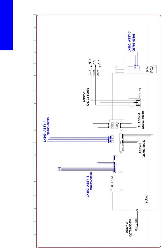
Circuit Diagram 7: Ebox Connections
16 |
Printer systems |
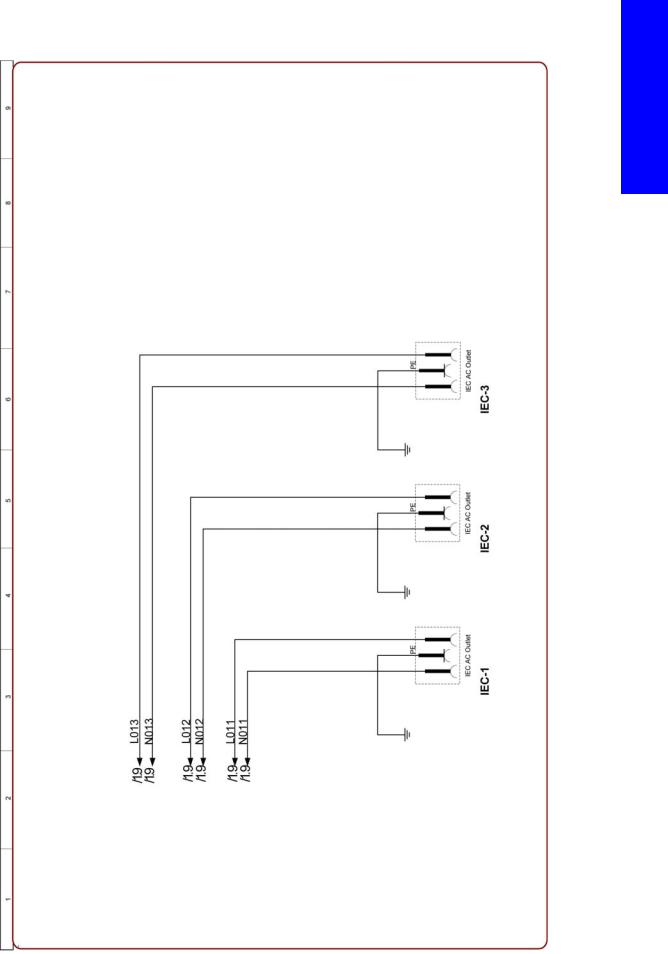
Circuit Diagram 8: PC Monitor Switch power connections
Printer systems
Printer systems |
17 |

Printer systems
Related tests, utilities, and calibrations
•Electrical cabinet diagnostic test Page 306.
Service parts
•Electrical Cabinet Page 451.
-Circuit Breaker
-Internal Fan
-Secondary Power Supplies
-Power Fuse Holder Block
-Safety Relay
-Scan Axis Brake Motor
-Vacuum Fan Power Transformer
-Main Power Switch
-Heating and Curing Temperature Sensor
-Power Fuses
-3 Phase line filter
-Main Power Breaker
-Heating and Curing Power Module
-
Removal and installation
• Electrical Cabinet Page 522.
18 |
Printer systems |
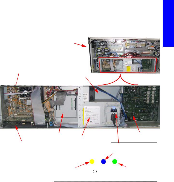
E-Box
The Ebox contains the main electrical control system in the printer. The e-box is the main processing and control element of the machine where all main electronic units are comprised.
Components
The Ebox is inside the Ecabinet and contains the following components:
ECabinet
Formatter PCA
ATX
Printer systems
|
|
|
|
|
|
|
|
|
|
|
Hard Disk |
Main Power Supply |
PrintMech PCA |
||||||||
|
|
|
||||||||
Upper and Lower PCI PCA |
ATX +24/42 PSU) |
|
||||||||
|
|
|
|
|
|
|
|
|
||
|
|
|
|
|
|
|
|
|
|
|
|
|
|
|
|
|
|
|
|
|
|
|
|
|
|
|
|
|
|
|
|
|
|
|
|
|
|
|
|
|
|
|
|
|
|
|
|
|
|
|
|
|
|
|
|
|
|
|
|
|
|
|
|
|
|
|
|
|
|
|
|
|
|
|
|
|
•Orange ON: System is powered (ACB 1 ON), System with Stand by power in the formatter waiting for the Front Panel power ON button to be pressed to start up the system.
Check this led when the printer is not powering on by pressing the front panel button to ensure the failure is not in the main power supply. If the led is Off AC power is not arriving to the main power supply or Main power supply switch in the main power supply is off or the Main power supply is faulty.
•Blue ON: Formatter Power system (ATX) Active.Internal computer system running
•Green ON: 24/42V of the second part of the main power supply activated. These 24 Volts are the main source for the complete system to work. Without these 24 Volts the e-cabinet electrical system will not work and the system will be impossible to be armed.
Printer systems |
19 |

Printer systems
Functionality
The E-box contains the primary electrical systems of the printer in one area.
Circuit Diagram: PCAs in the Ebox
PCA Boards and connections
Components
Formatter PCA
The formatter is the motherboard of the printer, with an Intel microprocessor of 256 MB RAM memory runs the operating system of the printer.
Hard disc drive
The HDD contains the main Firmware of the printer.
•The operating system is based on Montevista, an HP developed system.
•All calibration values, product number, serial number etc, are stored on the Hard Disc Drive. In order to make sure that this information is not lost in the case of a failure of the HDD, a backup is made:
-In the Main Interconnect Board for all the other information (other calibrations, total ink consumption etc).
-In the ISM board for information related with the ISM area (calibrations of the ink sensors, level of ink in the intermediate tanks, etc).
NOTE: In order to prevent the loss of calibration values, never replace the Hard disc system and the ISS Main Board or the Hard disc system and the Main Interconnect Board at the same time.
Upper and Lower Engine PCI Board
These two boards are the main controllers of the printer. They are responsible for all real-time processing and are the ultimate controllers of all electromechanical systems.
The Lower Engine PCI Board controls all substrate path components (Drive Roller, Spindle Motors, OMAS, etc.), and the link to the following controllers: Controllers of the PH cleaning roller (situated on the main interconnect board). The one connected to the remote controller board controlling the capping station movement motor. Both controllers are connected through the same bus (MICC).
20 |
Printer systems |

The Upper Engine PCI Board controls all non-substrate path components (carriage, scan axis motor, scan beam height/PPS, PH cleaning assembly, service station, etc).
Printmech Board
The Printmech Board is mainly used to drive the four substrate advance motors.
•2 Front Spindle motors (connected in series)
•1 Rear Spindle motor.
•1 Media advance motor (the drive roller motor)
NOTE: The motors are driven by 42V obtained from the secondary power supply which is located inside the electrical cabinet.
NOTE: To check that the 42V power supply arrives from the secondary power supply, see the V Power 2 LED located on the Printmech Board.
Printmech leds
Printer systems
Printer systems |
21 |

Printer systems
Main Interconnect Board connections
Most of the signals to or from the electronics box pass through the interconnect board. All of the cables connected to the Main Interconnect Board have labels indicating to which connection it should be connected.
J306
J300 |
|
|
|
|
|
|
|
|
|
||
|
|
|
|
|
|
|
|
|
|
J301 |
|
|
|
J308 |
|
|
|
|
|
|
J305 |
|
|
|
|
|
|
|
|
|
|
|
|
||
J307 |
|
|
|
|
|
|
|
|
|
|
J310 |
|
J4 |
J5 |
J7 |
J10 |
|
J13 |
J18 |
J19 |
|
J22 |
|
|
|
|
|
|
|
|
|||||
J3 |
|
|
|
J11 |
|
|
|
|
|
|
|
|
|
|
|
|
|
|
|
|
|
J23 |
|
|
|
|
|
|
|
|
J26 |
J17 |
J16 |
J20 |
|
|
|
|
|
|
|
|
|
|
|
|
|
J1 |
|
J27 |
J6 |
J8 |
|
J12 |
J15 |
|
J21 |
||
|
|
|
|
|
|
|
|||||
|
|
|
|
|
|
|
|
|
|
|
|
J Plug |
|
|
|
Description |
|
|
J Plug |
|
Description |
|
|
|
|
|
|
|
|
|
|
|
|||
J1 |
|
Scan Axis Motor data |
|
|
J16 |
Power& Control for PPS rear right motor PH |
|||||
|
|
|
Cleaning Roller motors & Capping Station 24v |
||||||||
|
|
|
|
|
|
|
|
power to remote controller |
|
|
|
|
|
|
|
|
|
|
|
|
|||
J3 |
|
Drop Detector |
|
|
|
J17 |
Power & Motor control for PPS front right motor & |
||||
|
|
|
|
vacuum controller (24v & 5v) |
|
|
|||||
|
|
|
|
|
|
|
|
|
|
||
|
|
|
|
|
|
|
|
|
|||
J4 |
|
Front Panel |
|
|
|
J18 |
Roll to Free Floor Control/power |
|
|||
|
|
|
|
|
|
|
|||||
J5 |
|
Remote Control Board (Service Station) |
|
J19 |
Power 24v (E-Cabinet, PPS, ISS) |
|
|||||
|
|
|
|
|
|
|
|
||||
J6 |
|
Remote Control Board (PPS) |
|
|
J22, J23 |
From secondary power supply 42v |
|
||||
|
|
|
|
|
|
|
|
|
|||
J10 |
|
Media Input (Rear Spindle System) |
|
|
J300 |
Encoder readers from the Printhead cleaning |
|||||
|
|
|
Rollers to the Upper Engine PCI board |
|
|||||||
|
|
|
|
|
|
|
|
|
|||
|
|
|
|
|
|
|
|
|
|||
J7 |
|
ISM 1 (Ink system Module: data 1) |
|
|
J301 |
42v from secondary 42 v power supply to |
|||||
|
|
|
PrintMech |
|
|
|
|||||
|
|
|
|
|
|
|
|
|
|
|
|
|
|
|
|
|
|
|
|
|
|||
J8 |
|
ISM 2 (Ink system Module: data 2) |
|
|
J306 |
To upper engine PCI Board |
|
|
|||
|
|
|
|
|
|
|
|
||||
J12 |
|
PH Cleaning System data (Encoders) |
|
J307 |
To lower engine PCI Board |
|
|
||||
|
|
|
|
|
|
|
|||||
J13 |
|
Front Right PPS (data) Encoder+switch |
|
J308 |
Front Panel Intermediate cable |
|
|||||
|
|
|
|
|
|
|
|
|
|||
J26 |
|
Rear Right PPS (data) Encoder+switch |
|
J305/J310 |
To Printmech 42v |
|
|
|
|||
|
|
|
|
|
|
|
|
||||
J15 |
|
Ecabinet Faulty Signals |
|
|
J20 |
Power supply to Carriage 24v |
|
||||
|
|
|
|
|
|
|
|||||
J11 |
|
Media Output (Front spindle system Encoder) |
|
J21 |
Power supply to Carriage 42v |
|
|||||
|
|
|
|
|
|
|
|
|
|
|
|
|
|
|
|
|
|
|
J27 |
OMAS/Vacuum control data |
|
|
|
|
|
|
|
|
|
|
|
|
|
|
|
22 |
Printer systems |
Main Interconnect Board LEDs
1 |
2 |
12
11 |
|
|
|
9 |
7 |
5 |
3 |
|
|||
|
|
10 

 4
4
8
6
Number |
Description |
Number |
Description |
|
|
|
|
|
|
1 |
24 LEDs (DS6 to DS29) |
7 |
From PPS encoder (rear, right)(DS36) |
|
|
|
|
|
|
2 |
ATX from Main Power Supply+12v, +5 (including |
8 |
From PPS encoder (front, right) (DS35) |
|
5v stand-by) |
||||
|
|
|
||
|
|
|
|
|
3 |
Not used |
9 |
12v from main power supply going to Front |
|
Panel (DS39) |
||||
|
|
|
||
|
|
|
|
|
4 |
Power temperature sensor |
10 |
24v to Scan Axis motor (DS40) |
|
|
|
|
|
|
5 |
5v for the PPS encoder (rear, right)(DS41) |
11 |
Scan Axis motor comms signal (DS32-33) |
|
|
|
|
|
|
6 |
5v for the PPS encoder (front, right)(DS37) |
12 |
From Scan Axis Motor (DS34) |
|
|
|
|
|
Photo detail of Main Interconnect
Printer systems
Printer systems |
23 |

Printer systems
Pin outs of the Main Interconnect
24 |
Printer systems |

Pin outs of the Main Interconnect
Labels on the cables
Labels are attached to the cables to identify where the cables go to, and in some cases identify the functionality of the cable.
The’ J17’ on the label identifies the J17 connector on the Main Interconnect Board. 
The ‘INT’ on the label signifies Main INTerconnect Board, which this cable is connected to
Printer systems
Printer systems |
25 |

Printer systems
Label abbreviations
Related part |
Abbreviation on label |
|
|
Switch |
SW |
|
|
Encoder |
ENC |
|
|
Power |
PWR |
|
|
Lan |
LAN |
|
|
Cover |
CV |
|
|
Main Interconnect Board |
INT |
|
|
Engine upper PCI board |
ENG 0 |
|
|
Engine lower PCI board |
ENG 1 |
|
|
PrintMech board |
PM |
|
|
Hard Disk Drive |
HDD |
|
|
Main Power Supply |
PWR |
|
|
Power Cabinet |
PWR CAB |
|
|
Secondary 24V Power supply |
PWR CAB SEC 24V |
|
|
Secondary 42V Power supply |
PWR CAB SEC 42V |
|
|
E-cabinet 24V intermediate connection |
PWR CAB 24V Out |
|
|
IR temperature Sensor - Left (Curing) |
SAX TS - LEFT |
|
|
CUR IR temperature Sensor - Right |
SAX TS - RIGHT PZ - H |
|
|
Print zone lamps power |
SAX PZ - H PWR |
|
|
Curing lamps power |
SAX CURING PWR |
|
|
Curing fans |
CURING FANS |
|
|
Front Spindle Motor |
FSM - T/B (Top/Bottom) |
|
|
Rear Spindle Motor |
RSM |
|
|
Drive Roller Motor |
MA (media advance) |
|
|
Carriage Lid Switch |
C Lid SW |
|
|
Printhead Board |
C PH1/2/3 |
|
|
Note: SAX=Scan Axis
L65500/LX600 Power lines specifications: 3 phase line
|
High Voltage system |
Low voltage systems |
|
|
|
Input voltage |
3 x 380-415V~ (-10%+6%) |
3 x 200-220V~ (-10%) |
|
|
|
Circuit Breaker |
20A |
32A |
|
|
|
Input frequency |
50Hz |
60Hz |
|
|
|
Power consumption |
12kW |
12kW |
|
|
|
maximum load current (per phase) |
32A |
32A |
|
||
L65500/LX600 Power lines specifications: Single phase line |
||
|
High Voltage system |
Low voltage systems |
|
|
|
Input voltage (phase to neutral) |
3 x 220-240V~ (-10%+6%) |
115-127 V~ (-10%) (Japan 200 V~) |
|
|
|
Input frequency |
50Hz |
60Hz |
|
|
|
26 |
Printer systems |

|
High Voltage system |
Low voltage systems |
|
|
|
Power consumption |
1kW |
1kW |
|
|
|
maximum load current (per phase) |
10A |
10A |
|
|
|
LX800 Power lines specifications: 3 phase line |
|
|
|
|
|
|
High Voltage system |
Low voltage systems |
|
|
|
Input voltage (line to line) |
3 x 380-415V~ (-10%+6%) |
3 x 200-220V~ (-10%) |
|
|
|
Input frequency |
50Hz |
60Hz |
|
|
|
Power consumption |
15kW |
15kW |
|
|
|
maximum load current (per phase) |
30A |
50A |
|
|
|
LX800 Power lines specifications: Single phase line |
|
|
|
|
|
|
High Voltage system |
Low voltage systems |
|
|
|
Input voltage (line to line) |
200-240V~ (-10%+6%) |
115-127 V~ (-10%) (Japan 200 V~) |
|
|
|
Input frequency |
50Hz |
60Hz |
|
|
|
Power Consumption |
1kW |
1kW |
|
|
|
Maximum load current (per phases) |
10A |
10A |
|
|
|
Related tests, utilities, and calibrations
•From diagnostic mode: Electronics Page 291.
•Service Utilities: Electrical system Page 291.
Service parts
•Electrical Cabinet Page 451.
Removal and installation
Electronics Page 509.
Printer systems
Printer systems |
27 |
Printer systems
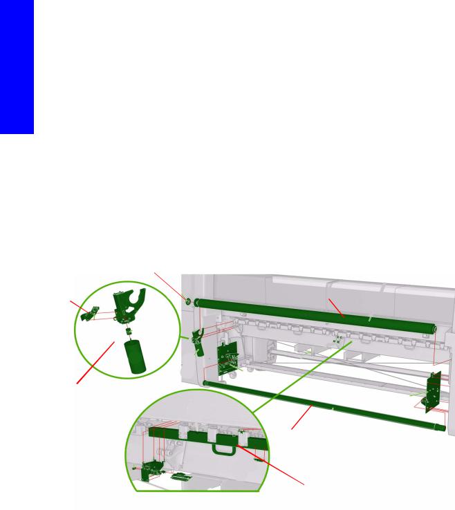
Substrate path
The media roll is mounted on the rear spindle and is collected on the front spindle. Media goes from the rear spindle over the drive roller, over the print platen, over the diverter and onto the front spindle.
Each of the spindles has its own motor system. Vacuum is applied at the level of the print platen to keep the substrate flat.
The advance of the media is applied by the motor of the drive roller. There is a pinch mechanism to prevent the substrate slipping against the drive roller.
The accuracy of the substrate advance is controlled with two components:
•The Driver Roller Encoder disc.
•The OMAS: This is an optical sensor which works like a camera taking pictures of the media’s fibre, the pictures are then compared, measuring actual distances during movements in order to apply small corrections in the advancement of the substrate.
Components
|
Drive Roller Encoder disc |
|
Drive |
Drive Roller |
|
Roller |
||
|
||
Encoder |
|
|
sensor |
|
Drive Roller Motor Assembly
Rear Spindle
Pinch mechanism
28 |
Printer systems |
 Loading...