


 Loading...
HP Notebook 14
Maintenance and Service Guide IMPORTANT! This document is intended for HP authorized service providers only.
© Copyright 2016 HP Development Company,
L.P.
Bluetooth is a trademark owned by its proprietor and used by HP Inc. under license. Intel and Celeron are trademarks of Intel Corporation in the U.S. and other countries. Microsoft and Windows are either registered trademarks or trademarks of Microsoft Corporation in the United States and/or other countries.
Product notice
This guide describes features that are common to most models. Some features may not be available on your computer.
Not all features are available in all editions of Windows. This computer may require upgraded and/or separately purchased hardware, drivers and/or software to take full advantage of Windows functionality. Go to http://www.microsoft.com for details.
The information contained herein is subject to change without notice. The only warranties for HP products and services are set forth in the express warranty statements accompanying such products and services. Nothing herein should be construed as constituting an additional warranty. HP shall not be liable for technical or editorial errors or omissions contained herein.
First Edition: February 2015
Document Part Number: 855909-001

Important Notice
 CAUTION: This computer does not have user-replaceable parts. Your computer includes parts that should only be accessed by an authorized service provider. Accessing parts described in Chapter 5, "Removal and replacement procedures for authorized service provider parts," can damage the computer or void your warranty.
iii
iv Important Notice

Safety warning notice
 WARNING! To reduce the possibility of heat-related injuries or of overheating the device, do not place the device directly on your lap or obstruct the device air vents. Use the device only on a hard, at surface. Do not allow another hard surface, such as an adjoining optional printer, or a soft surface, such as pillows or rugs or clothing, to block air ow. Also, do not allow the AC adapter to contact the skin or a soft surface, such as pillows or rugs or clothing, during operation. The device and the AC adapter comply with the user-accessible surface temperature limits de ned by the International Standard for Safety of Information Technology Equipment (IEC 60950-1).
v
vi Safety warning notice

Table of contents
1 Product description ....................................................................................................................................... |
1 |
2 External component dent c t on .................................................................................................................. |
2 |
Right side (select products only) ........................................................................................................................... |
2 |
Left side ................................................................................................................................................................. |
2 |
Display .................................................................................................................................................................... |
3 |
Front ....................................................................................................................................................................... |
4 |
Top .......................................................................................................................................................................... |
5 |
TouchPad ............................................................................................................................................. |
5 |
Lights ................................................................................................................................................... |
6 |
Buttons ................................................................................................................................................ |
7 |
Keys ..................................................................................................................................................... |
8 |
Using the action keys .......................................................................................................................... |
8 |
Locating system information ................................................................................................................................ |
9 |
3 Illustrated parts catalog .............................................................................................................................. |
10 |
Computer major components .............................................................................................................................. |
10 |
Display assembly subcomponents ...................................................................................................................... |
13 |
Miscellaneous parts ............................................................................................................................................. |
14 |
4 Removal and replacement procedures preliminary requirements .................................................................... |
15 |
Tools required ...................................................................................................................................................... |
15 |
Service considerations ......................................................................................................................................... |
15 |
Plastic parts ....................................................................................................................................... |
15 |
Cables and connectors ...................................................................................................................... |
16 |
Drive handling ................................................................................................................................... |
16 |
Grounding guidelines ........................................................................................................................................... |
17 |
Electrostatic discharge damage ........................................................................................................ |
17 |
Packaging and transporting guidelines .......................................................................... |
18 |
Workstation guidelines ................................................................................................... |
18 |
Equipment guidelines ..................................................................................................... |
19 |
5 Removal and replacement procedures for authorized service provider parts .................................................... |
20 |
Component replacement procedures .................................................................................................................. |
20 |
Base enclosure .................................................................................................................................. |
20 |
Battery ............................................................................................................................................... |
22 |
vii
Optical drive dummy ......................................................................................................................... |
22 |
Hard drive .......................................................................................................................................... |
23 |
Memory .............................................................................................................................................. |
25 |
WLAN module .................................................................................................................................... |
28 |
Heat sink and fan ............................................................................................................................... |
30 |
Speakers ............................................................................................................................................ |
32 |
Microphone ........................................................................................................................................ |
34 |
System board .................................................................................................................................... |
36 |
WLAN cable ........................................................................................................................................ |
39 |
Display assembly ............................................................................................................................... |
41 |
Webcam ............................................................................................................................................. |
45 |
6 Using Setup Utility (BIOS) ............................................................................................................................. |
47 |
Starting Setup Utility (BIOS) ................................................................................................................................ |
47 |
Updating Setup Utility (BIOS) .............................................................................................................................. |
47 |
Determining the BIOS version ........................................................................................................... |
47 |
Downloading a BIOS update .............................................................................................................. |
48 |
7 Backing up, restoring, and recovering ........................................................................................................... |
49 |
Creating recovery media and backups ................................................................................................................ |
49 |
Creating HP Recovery media (select products only) ......................................................................... |
49 |
Using Windows tools ........................................................................................................................................... |
50 |
Restore and recovery ........................................................................................................................................... |
50 |
8 Using HP PC Hardware Diagnostics (UEFI) ....................................................................................................... |
51 |
Downloading HP PC Hardware Diagnostics (UEFI) to a USB device .................................................................... |
51 |
9 pec c t ons .............................................................................................................................................. |
53 |
Computer speci cations ...................................................................................................................................... |
53 |
35.56 cm (14-in) display speci cations .............................................................................................................. |
54 |
Hard drive speci cations ..................................................................................................................................... |
54 |
10 Power cord set requirements ...................................................................................................................... |
56 |
Requirements for all countries ............................................................................................................................ |
56 |
Requirements for speci c countries and regions ................................................................................................ |
56 |
11 Recycling .................................................................................................................................................. |
58 |
Index ............................................................................................................................................................. |
59 |
viii

1Product description
Category |
Description |
|
|
|
|
Product Name |
HP Notebook 14 |
|
|
|
|
Processors |
● Intel® Celeron® Processor 3215U |
|
|
● Fifth generation Intel® Core™ i3-5005U |
|
|
|
|
Panel |
14" HD LCD, 16:9 LED type, resolution 1366 x 768 |
|
|
|
|
Memory |
SODIMM 4 GB PC3L 12800 (maximum 8 GB) |
|
|
|
|
Hard drive |
SATA 500 GB 5400 RPM 7mm |
|
|
|
|
Optical drive dummy |
Dummy, ODD |
|
|
Bezel, ODD |
|
|
|
|
Audio and video |
● Audio-out (headphone)/Audio-in (microphone) combo jack |
|
|
● |
Internal microphone |
|
● |
HDMI port |
|
|
|
Ethernet |
RJ-45 network jack |
|
|
|
|
Wireless |
Wireless LAN—IEEE802.11 b/g/n support |
|
|
|
|
|
Wireless LAN+ Bluetooth (select products only)—IEEE802.11 b/g/n support, BT 4.0, USB interface |
|
|
|
|
Ports |
● |
2 x USB2.0 |
|
● |
1 x USB3.0 |
|
|
|
External media cards |
Supports optional SD/MS/MS Pro memory cards |
|
|
|
|
Power requirements |
19.5 V dc @ 2.31 A – 45 W |
|
|
|
|
Security |
Security cable slot (select products only) |
|
|
|
|
Operating system |
Windows 10 64-bit |
|
|
|
|
Serviceability |
End user replaceable parts: |
|
|
● |
AC adapter |
|
● |
Power cord |
|
|
|
1

2 External component dent c t on
Right side (select products only)
Component |
|
Description |
|
|
|
(1) |
Optical drive (select products only) |
Depending on your computer, reads an optical disc or reads and |
|
|
writes to an optical disc. |
|
|
NOTE: For disc compatibility information, type help in the |
|
|
taskbar search box, select Help and Support, and then type |
|
|
disc compatibility in the search box. |
|
|
|
(2) |
Optical drive eject button (select products only) |
Releases the optical drive disc tray. |
|
|
|
Left side
Component |
|
Description |
|
|
|
|
|
(1) |
Security cable slot |
Attaches an optional security cable to the computer. |
|
|
|
NOTE: The security cable is designed to act as a deterrent, but |
|
|
|
it may not prevent the computer from being mishandled or |
|
|
|
stolen. |
|
|
|
|
|
(2) |
Power connector |
Connects an AC adapter. |
|
|
|
|
|
(3) |
HDMI port |
Connects an optional video or audio device, such as a high- |
|
|
|
de |
nition television, any compatible digital or audio component, |
|
|
or a high-speed igh-De nition Multimedia Interface (HDMI) |
|
|
|
device. |
|
|
|
|
|
(4) |
RJ-45 (network) jack/status lights |
Connects a network cable. |
|
|
|
● |
White: The network is connected. |
|
|
● |
Amber: Activity is occurring on the network. |
|
|
|
|
2 Chapter 2 External component identi cation
Component |
|
Description |
|
|
|
(5) |
USB 2.0 port |
Connects an optional USB device, such as a keyboard, mouse, |
|
|
external drive, printer, scanner or USB hub. |
|
|
|
(6) |
USB 3.0 port |
Connects an optional USB device, such as a keyboard, mouse, |
|
|
external drive, printer, scanner or USB hub. |
|
|
|
(7) |
Vent |
Enables air ow to cool internal components. |
|
|
NOTE: The computer fan starts up automatically to cool |
|
|
internal components and prevent overheating. It is normal for |
|
|
the internal fan to cycle on and o during routine operation. |
|
|
|
Display
Component |
Description |
|
|
|
|
(1) |
WLAN antennas (2)* |
Send and receive wireless signals to communicate with wireless local |
|
|
area networks (WLANs). |
|
|
|
(2) |
Webcam |
Records video and captures photographs. Some products allow you |
|
|
to video conference and chat online using streaming video. |
|
|
To use a webcam (integrated camera): |
|
|
▲ Type camera in the taskbar search box, and then select |
|
|
Camera. |
|
|
|
(3) |
Webcam light |
On: The webcam is in use. |
*The antennas are not visible from the outside of the computer. For optimal transmission, keep the areas immediately around the antenna free from obstructions.
For wireless regulatory notices, see the section of the Regulatory, Safety, and Environmental Notices that applies to your country or region.
To access this guide:
Display 3

Component |
Description |
▲Select the Start button, select All apps, select HP Help and Support, and then select HP Documentation.
Front
Component |
Description |
|
|
|
|
|
|
(1) |
Speakers (2) |
Produce sound. |
|
|
|
|
|
(2) |
Audio-out (headphone)/Audio-in |
Connects optional powered stereo speakers, |
|
|
(microphone) combo jack |
headphones, earbuds, a headset, or a |
|
|
|
television audio cable. Also connects an |
|
|
|
optional headset microphone. This jack does |
|
|
|
not support optional standalone |
|
|
|
microphones. |
|
|
|
WARNING! To reduce the risk of personal |
|
|
|
injury, adjust the volume before putting on |
|
|
|
headphones, earbuds, or a headset. For |
|
|
|
additional safety information, refer to the |
|
|
|
Regulatory, Safety, and Environmental |
|
|
|
Notices. |
|
|
|
To access this guide: |
|
|
|
▲ Select the Start button, select All |
|
|
|
|
apps, select HP Help and Support, and |
|
|
|
then select HP Documentation. |
|
|
NOTE: When a device is connected to the |
|
|
|
jack, the computer speakers are disabled. |
|
|
|
|
|
(3) |
USB 2.0 port |
Connects an optional USB device, such as a |
|
|
|
keyboard, mouse, external drive, printer, |
|
|
|
scanner or USB hub. |
|
|
|
|
|
(4) |
Memory card reader |
Reads optional memory cards that enable |
|
|
|
you to store, manage, share, or access |
|
|
|
information. |
|
|
|
To insert a card: |
|
|
|
1. |
Hold the card label-side up, with |
|
|
|
connectors facing the computer. |
|
|
2. |
Insert the card into the memory card |
reader, and then press in on the card until it is rmly seated.
To remove a card:
▲ Press in on the card, and then remove it from the memory card reader.
4 Chapter 2 External component identi cation

Top
TouchPad
Component |
|
Description |
|
|
|
(1) |
TouchPad zone |
Reads your nger gestures to move the pointer or activate items |
|
|
on the screen. |
|
|
|
(2) |
Left TouchPad button |
Functions like the left button on an external mouse. |
|
|
|
(3) |
Right TouchPad button |
Functions like the right button on an external mouse. |
|
|
|
Top 5
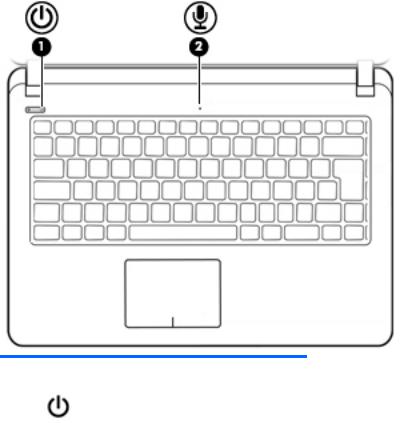
Lights
Component |
|
Description |
|
|
|
|
|
(1) |
Power light |
● |
On: The computer is on. |
|
|
● |
Blinking: The computer is in the Sleep state, a power- |
|
|
|
saving state. The computer shuts o power to the display |
|
|
|
and other unneeded components. |
|
|
● |
The computer is o or in Hibernation. Hibernation is a |
|
|
|
power-saving state that uses the least amount of power. |
|
|
|
|
(2) |
Internal microphone |
Records sound. |
|
|
|
|
|
6 Chapter 2 External component identi cation

Buttons
Component |
|
Description |
|
|
|
|
|
(1) |
Power button |
● |
When the computer is o , press the button to turn on the |
|
|
|
computer. |
|
|
● |
When the computer is on, press the button brie y to |
|
|
|
initiate Sleep. |
|
|
● |
When the computer is in the Sleep state, press the button |
|
|
|
brie y to exit Sleep. |
|
|
● |
When the computer is in Hibernation, press the button |
|
|
|
brie y to exit Hibernation. |
|
|
CAUTION: Pressing and holding down the power button results |
|
|
|
in the loss of unsaved information. |
|
|
|
If the computer has stopped responding and shutdown |
|
|
|
procedures are ine ective, press and hold the power button |
|
|
|
down for at least 5 seconds to turn o the computer. |
|
|
|
To learn more about your power settings, see your power |
|
|
|
options. |
|
|
|
▲ |
Type power in the taskbar search box, and then select |
Power and sleep settings.
‒ or –
Right-click the Start button, and then select Power
Options.
Top 7
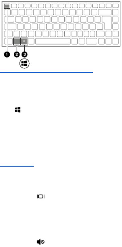
Keys
Component |
|
Description |
|
|
|
(1) |
esc key |
Executes frequently used system functions when pressed in |
|
|
combination with the fn key. |
|
|
|
(2) |
fn key |
Executes frequently used system functions when pressed in |
|
|
combination with the esc key, action keys, or the spacebar. |
|
|
|
(3) |
Windows key |
Opens the Start menu. |
|
|
NOTE: Pressing the Windows key again will close the Start |
|
|
menu. |
|
|
|
Using the action keys
●An action key performs an assigned function.
●The icon on each action key illustrates the function for that key.
●To use an action key, press and hold the key.
Function key |
Icon |
Description |
|
|
|
f1 |
|
Suspend |
|
|
|
f2 |
|
Power saving |
|
|
|
f3 |
|
Display switch |
|
|
|
f4 |
|
Radio on/o |
|
|
|
f5 |
|
On-screen display |
|
|
|
f6 |
|
TouchPad on/o |
|
|
|
f7 |
|
Webcam on/o |
|
|
|
f8 |
|
Mutes or restores speaker sound. |
|
|
|
8 Chapter 2 External component identi cation
Function key |
Icon |
Description |
|
|
|
f9 |
|
Decreases speaker volume incrementally while you hold down the key. |
|
|
|
f10 |
|
Increases speaker volume incrementally while you hold down the key. |
|
|
|
f11 |
|
Decreases the screen brightness incrementally as long as you hold down the key. |
|
|
|
f12 |
|
Increases the screen brightness incrementally as long as you hold down the key. |
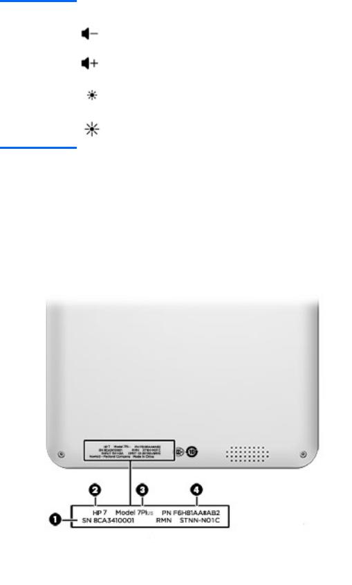
Locating system information
Important system information is located on the back of the computer. You may need the information when travelling internationally or when you contact support:
(1): Serial number
(2): Product number
(3): Model number
(4): Warranty period
Locating system information |
9 |

3Illustrated parts catalog
Computer major components
 NOTE: HP continually improves and changes product parts. For complete and current information on supported parts for your computer, go to http://partsurfer.hp.com, select your country or region, and then follow the on-screen instructions.


 NOTE: Details about your computer, including model, serial number, product key, and length of warranty, are on the service tag at the bottom of your computer. See Locating system information on page 9 for details.
10 Chapter 3 Illustrated parts catalog

Item |
Component |
Spare part number |
|
|
|
(1) |
Display assembly (see Display assembly subcomponents on page 13) |
|
|
|
|
Computer major components 11

Item |
Component |
Spare part number |
|
|
|
(2) |
Top cover (includes keyboard and TouchPad) |
854457-001 |
|
|
|
(3) |
Hard drive (see Hard drive on page 23) |
683839-855 |
|
|
|
(4) |
Optical drive dummy (see Optical drive dummy on page 22) |
854470-001 |
|
|
|
(5) |
Battery (see Battery on page 22) |
854472-001 |
|
|
|
(6) |
Memory (see Memory on page 25) |
691799-855 |
|
|
|
(7) |
WLAN module (see WLAN module on page 28) |
792505-855 |
|
|
|
(8) |
RTC battery |
855483-001 |
|
|
|
(9) |
Webcam (see Webcam on page 45) |
854509-001 |
|
|
|
(10) |
Fan (see Heat sink and fan on page 30) |
854468-001 |
|
|
|
|
Heat sink (see Heat sink and fan on page 30) |
854469-001 |
|
|
|
(11) |
Speaker (see Speakers on page 32) |
854475-001 |
|
|
|
(12) |
System board (see System board on page 36) |
854479-001 |
|
|
|
(13) |
Base enclosure |
854473-001 |
|
|
|
12 Chapter 3 Illustrated parts catalog
Display assembly subcomponents
Item |
Component |
Spare part number |
|
|
|
(1) |
Display bezel |
854447-001 |
|
|
|
(2) |
Microphone (see Microphone on page 34) |
854474-001 |
|
|
|
(3) |
Panel |
854448-001 |
|
|
|
(4) |
Hinge kit |
854508-001 |
|
|
|
(5) |
WLAN antennas |
854450-001 |
|
|
854451-001 |
|
|
|
(6) |
WLAN cable |
792505-855 |
|
|
|
(7) |
Back cover |
854507-001 |
|
|
|
|
Not shown: |
|
|
|
|
|
Display cable |
854449-001 |
|
|
|
|
Touch panel cable (select products only) |
854477-001 |
|
|
|
Display assembly subcomponents 13
Loading...