


 Loading...
HPE OfficeConnect 1820 Switch Series
Installation and Getting Started Guide
Abstract
This guide provides information on installing and configuring the HPE OfficeConnect 1820 Switch Series. Hardware specifications and troubleshooting information is also provided.
Part Number: 5200-2849
Published: March 2017
Edition: 1
© 2017, 2017 Hewlett Packard Enterprise Development LP
Notices
The information contained herein is subject to change without notice. The only warranties for Hewlett Packard Enterprise products and services are set forth in the express warranty statements accompanying such products and services. Nothing herein should be construed as constituting an additional warranty. Hewlett Packard Enterprise shall not be liable for technical or editorial errors or omissions contained herein.
Confidential computer software. Valid license from Hewlett Packard Enterprise required for possession, use, or copying. Consistent with FAR 12.211 and 12.212, Commercial Computer Software, Computer Software Documentation, and Technical Data for Commercial Items are licensed to the U.S. Government under vendor's standard commercial license.
Links to third-party websites take you outside the Hewlett Packard Enterprise website. Hewlett Packard Enterprise has no control over and is not responsible for information outside the Hewlett Packard Enterprise website.
Acknowledgments
Intel®, Itanium®, Pentium®, Intel Inside®, and the Intel Inside logo are trademarks of Intel Corporation in the United States and other countries.
Microsoft® and Windows® are either registered trademarks or trademarks of Microsoft Corporation in the United States and/or other countries.
Adobe® and Acrobat® are trademarks of Adobe Systems Incorporated. Java® and Oracle® are registered trademarks of Oracle and/or its affiliates. UNIX® is a registered trademark of The Open Group.
Contents
Switch overview........................................................................................... |
5 |
Switch hardware features.................................................................................................................... |
5 |
Network Ports........................................................................................................................... |
8 |
LEDs......................................................................................................................................... |
8 |
Mode Button........................................................................................................................... |
10 |
Reset button........................................................................................................................... |
10 |
Power Connector.................................................................................................................... |
10 |
Switch Features................................................................................................................................. |
10 |
Installing the Switch.................................................................................. |
12 |
Included Parts.................................................................................................................................... |
12 |
Installation precautions...................................................................................................................... |
14 |
Installation Procedure........................................................................................................................ |
15 |
1. Prepare the installation site................................................................................................ |
16 |
Installation space requirements................................................................................... |
16 |
2. Verify the Switch Passes Self Test...................................................................................... |
16 |
3. Mount the switch................................................................................................................. |
19 |
Rack or cabinet mounting............................................................................................ |
19 |
Wall or Under-Table Mounting...................................................................................... |
20 |
Horizontal surface mounting........................................................................................ |
21 |
Using a Kensington security cable............................................................................... |
22 |
4. Connect the Switch to a Power Source.............................................................................. |
22 |
5. Connect the Network Cables.............................................................................................. |
23 |
6. Installing or removing SFPs................................................................................................ |
23 |
Installing the SFPs:...................................................................................................... |
24 |
Removing the SFPs..................................................................................................... |
24 |
Connecting cables to SFPs.......................................................................................... |
24 |
Configuring the Switch............................................................................. |
25 |
Initial Configuration............................................................................................................................ |
25 |
Using the 192.168.1.1 IP address..................................................................................................... |
26 |
Where to Go From Here.................................................................................................................... |
26 |
Troubleshooting......................................................................................... |
27 |
Basic troubleshooting tips.................................................................................................................. |
27 |
Diagnosing with the LEDs................................................................................................................. |
27 |
LED patterns for General Switch Troubleshooting................................................................. |
27 |
Diagnostic Tips....................................................................................................................... |
28 |
LED Patterns for PoE Troubleshooting................................................................................... |
29 |
Testing the switch by resetting it........................................................................................................ |
30 |
Restoring to Factory Defaults............................................................................................................ |
30 |
Websites..................................................................................................... |
31 |
Contents 3
Support and other resources................................................................... |
32 |
Accessing Hewlett Packard Enterprise Support................................................................................ |
32 |
Accessing updates............................................................................................................................ |
32 |
Customer self repair.......................................................................................................................... |
32 |
Remote support................................................................................................................................. |
33 |
Warranty information......................................................................................................................... |
33 |
Regulatory information...................................................................................................................... |
33 |
Documentation feedback................................................................................................................... |
34 |
Specifications............................................................................................ |
35 |
Switch Specifications......................................................................................................................... |
35 |
Physical.................................................................................................................................. |
35 |
Electrical................................................................................................................................. |
35 |
Environmental......................................................................................................................... |
36 |
Acoustics................................................................................................................................ |
36 |
Safety...................................................................................................................................... |
36 |
Standards.......................................................................................................................................... |
37 |
Cabling and Technology Information Specifications.......................................................................... |
37 |
Technology Distance Specifications....................................................................................... |
38 |
Mode Conditioning Patch Cord.......................................................................................................... |
38 |
Installing the Patch Cord......................................................................................................... |
39 |
Twisted-Pair Cable/Connector Pin-Outs............................................................................................ |
39 |
Straight-through Twisted-Pair Cable for10 Mbps or 100 Mbps Network Connections............ |
40 |
Cable Diagram............................................................................................................. |
40 |
Pin Assignments.......................................................................................................... |
41 |
Crossover Twisted-Pair Cable for10 Mbps or 100 Mbps Network Connection....................... |
41 |
Cable Diagram............................................................................................................. |
41 |
Pin Assignments.......................................................................................................... |
42 |
Straight-Through Twisted-Pair Cable for 1000 Mbps Network Connections.......................... |
42 |
Cable Diagram............................................................................................................. |
42 |
Pin Assignments.......................................................................................................... |
42 |
EMC Regulatory Statements..................................................................... |
43 |
Regulatory Statements...................................................................................................................... |
43 |
U.S.A...................................................................................................................................... |
43 |
Canada................................................................................................................................... |
43 |
Australia/New Zealand............................................................................................................ |
43 |
Japan...................................................................................................................................... |
43 |
Korea...................................................................................................................................... |
43 |
Taiwan..................................................................................................................................... |
44 |
4Contents
Switch overview
The HPE OfficeConnect 1820 Switch Series are multiport switches that can be used to build highperformance switched workgroup networks. These switches are store-and-forward devices that offer low latency for high-speed networking. Three of the switches also support the IEEE 802.3at standard for providing PoE+ power to connected devices.
Throughout this manual, these switches will be referred to as the 1820 8G Switch, 1820 24G Switch, 1820 48G Switch, 1820 8G PoE+ Switch, 1820 24G PoE+ Switch, and the 1820 48G PoE+ Switch.
•The 1820 8G Switch has 8 auto-sensing 10/100/1000BASE-T RJ-45 ports. Port 1 is a Power over Ethernet Powered Device (PoE PD) port. The switch can be powered by a network connection to port 1 from PoE power sourcing equipment (PSE), such as a PoE switch.
•The 1820 24G Switch has 24 auto-sensing 10/100/1000BASE-T RJ-45 ports and two SFP slots for supported HPE SFP fiber-optic transceivers (ports 25 and 26).
•The 1820 48G Switch has 48 auto-sensing 10/100/1000BASE-T RJ-45 ports and four SFP slots for supported HPE SFP fiber-optic transceivers (ports 49 to 52).
•The 1820 8G PoE+ Switch has 8 auto-sensing 10/100/1000BASE-T RJ-45 ports. The switch supports the IEEE 802.3at standard and is capable of providing 65 watts of PoE power through ports 1-4.
•The 1820 24G PoE+ Switch has 24 auto-sensing 10/100/1000BASE-T RJ-45 ports and two SFP slots for supported HPE SFP fiber-optic transceivers (ports 25 and 26). The switch supports the IEEE 802.3at standard and is capable of providing 185 watts of PoE power through ports 1-12.
•The 1820 48G PoE+ Switch has 48 auto-sensing 10/100/1000BASE-T RJ-45 ports and four SFP slots for supported HPE SFP fiber-optic transceivers (ports 49 to 52). The switch supports the IEEE 802.3at standard and is capable of providing 370 watts of PoE power through ports 1-24.
These switches can be directly connected to computers, printers, and servers to provide dedicated bandwidth to those devices, and you can build a switched network infrastructure by connecting the switch to hubs, other switches, or routers. In addition, these switches offer network management capabilities.
Switch hardware features
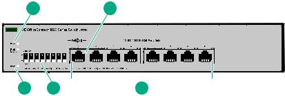
HPE OfficeConnect 1820 8G Switch (J9979A)
1 |
2 |
|
|
|
|
|
|
|
|
|
|
|
|
|
|
|
|
|
||||||||
|
|
|
|
|
|
|
|
|
|
|
|
|
|
|
|
|
|
|
|
|
|
|
|
|
|
|
|
|
|
|
|
|
|
|
|
|
|
|
|
|
|
|
|
|
|
|
|
|
|
|
|
|
|
|
|
|
|
|
|
|
|
|
|
|
|
|
|
|
|
|
|
|
|
|
|
|
|
|
|
|
|
|
|
|
|
|
|
|
|
|
|
|
|
|
|
|
|
|
|
|
|
|
|
|
|
|
|
|
|
|
|
|
|
|
|
|
|
|
|
|
|
|
|
|
|
|
|
|
|
|
|
|
|
|
|
|
|
|
|
|
|
|
|
|
|
|
|
|
|
|
|
|
|
|
|
|
|
|
|
|
|
|
|
|
|
|
|
|
|
|
|
|
|
|
|
|
|
|
|
|
|
|
|
|
|
|
|
|
|
|
|
|
|
|
|
|
|
|
|
|
|
|
|
|
|
|
|
|
|
|
|
|
|
|
|
|
|
|
|
|
|
|
|
|
|
|
|
|
|
|
|
|
|
|
|
|
|
|
|
|
|
|
5 |
4 |
|
|
3 |
|||
1Power and Fault/Locator LEDs
2PoE PD port
310/100/1000BASE-T RJ-45 ports
4Link/Act and Speed LEDs
5Reset button
HPE OfficeConnect 1820 24G Switch (J9980A)
Switch overview 5

1 |
2 |
|
|
|
|
|
|
|
|
|
|
|
|
|
|
|
|
|
|
|
|
|
|
|
|
|
|
|
|
|
|
|
3 |
||
|
|
|
|
|
|
|
|
|
|
|
|
|
|
|
|
|
|
|
|
|
|
|
|
|
|
|
|
|
|
|
|
|
|
|
|
|
|
|
|
|
|
|
|
|
|
|
|
|
|
|
|
|
|
|
|
|
|
|
|
|
|
|
|
|
|
|
|
|
|
|
|
|
|
|
|
|
|
|
|
|
|
|
|
|
|
|
|
|
|
|
|
|
|
|
|
|
|
|
|
|
|
|
|
|
|
|
|
|
|
|
|
|
|
|
|
|
|
|
|
|
|
|
|
|
|
|
|
|
|
|
|
|
|
|
|
|
|
|
|
|
|
|
|
|
|
|
|
|
|
|
|
|
|
|
|
|
|
|
|
|
|
|
|
|
|
|
|
|
|
|
|
|
|
|
|
|
|
|
|
|
|
|
|
|
|
|
|
|
|
|
|
|
|
|
|
|
|
|
|
|
|
|
|
|
|
|
|
|
|
|
|
|
|
|
|
|
|
|
|
|
|
|
|
|
|
|
|
|
|
|
|
|
|
|
|
|
|
|
|
|
|
|
|
|
|
|
|
|
|
|
|
5 |
|
|
4 |
||
1Power and Fault/Locator LEDs
2Link/Act and Speed LEDs
3SFP slots
410/100/1000BASE-T RJ-45 ports
5Reset button
HPE OfficeConnect 1820 48G Switch (J9981A)
1 |
|
|
|
|
|
|
|
|
2 |
|
|
|
|
|
|
|
|
|
|
|
|
|
|
|
|
|
|
|
|
|
|
|
|
|
|
|
|
|
|
3 |
|||||||||
|
|
|
|
|
|
|
|
|
|
|
|
|
|
|
|
|
|
|
|
|
|
|
|
|
|
|
|
|
|
|
|
|
|
|
|
|
|
|
|
|
|
|
|
|
|
|
|
|
|
|
|
|
|
|
|
|
|
|
|
|
|
|
|
|
|
|
|
|
|
|
|
|
|
|
|
|
|
|
|
|
|
|
|
|
|
|
|
|
|
|
|
|
|
|
|
|
|
|
|
|
|
|
|
|
|
|
|
|
|
|
|
|
|
|
|
|
|
|
|
|
|
|
|
|
|
|
|
|
|
|
|
|
|
|
|
|
|
|
|
|
|
|
|
|
|
|
|
|
|
|
|
|
|
|
|
|
|
|
|
|
|
|
|
|
|
|
|
|
|
|
|
|
|
|
|
|
|
|
|
|
|
|
|
|
|
|
|
|
|
|
|
|
|
|
|
|
|
|
|
|
|
|
|
|
|
|
|
|
|
|
|
|
|
|
|
|
|
|
|
|
|
|
|
|
|
|
|
|
|
|
|
|
|
|
|
|
|
|
|
|
|
|
|
|
|
|
|
|
|
|
|
|
|
|
|
|
|
|
|
|
|
|
|
|
|
|
|
|
|
|
|
|
|
|
|
|
|
|
|
|
|
|
|
|
|
|
|
|
|
|
|
|
|
|
|
|
|
|
|
|
|
|
|
|
|
|
|
5 |
|
|
|
4 |
|
||
1Power and Fault/Locator LEDs
2Link/Act and Speed LEDs
3SFP slots
410/100/1000BASE-T RJ-45 ports
5Reset button
HPE OfficeConnect 1820 8G PoE+ (65W) Switch (J9982A)
|
1 |
|
|
2 |
|
|
|
|
|
3 |
|
|
||||||||||||||
|
|
|
|
|
|
|
|
|
|
|
|
|
|
|
|
|
|
|
|
|
|
|
|
|
|
|
|
|
|
|
|
|
|
|
|
|
|
|
|
|
|
|
|
|
|
|
|
|
|
|
|
|
|
|
|
|
|
|
|
|
|
|
|
|
|
|
|
|
|
|
|
|
|
|
|
|
|
|
|
|
|
|
|
|
|
|
|
|
|
|
|
|
|
|
|
|
|
|
|
|
|
|
|
|
|
|
|
|
|
|
|
|
|
|
|
|
|
|
|
|
|
|
|
|
|
|
|
|
|
|
|
|
|
|
|
|
|
|
|
|
|
|
|
|
|
|
|
|
|
|
|
|
|
|
|
|
|
|
|
|
|
|
|
|
|
|
|
|
|
|
|
|
|
|
|
|
|
|
|
|
|
|
|
|
|
|
|
|
|
|
|
|
|
|
|
|
|
|
|
|
|
|
|
|
|
|
|
|
|
|
|
|
|
|
|
|
|
|
|
|
|
|
|
|
|
|
|
|
|
|
|
|
|
|
|
|
|
|
|
|
|
|
|
|
|
|
|
|
|
|
|
|
|
|
|
|
|
|
|
|
|
|
|
|
|
|
|
|
|
6 |
5 |
4 |
1Power and Fault/Locator LEDs
6Switch overview
2PoE+ ports 1-4
3Link/Act and Mode LEDs
410/100/1000BASE-T RJ-45 ports
5Reset button
6Mode button
HPE OfficeConnect 1820 24G PoE+ (185W) Switch (J9983A)
1 |
|
|
2 |
3 |
|
|
|
|
|
4 |
||||||||||
|
|
|
|
|
|
|
|
|
|
|
|
|
|
|
|
|
|
|
|
|
|
|
|
|
|
|
|
|
|
|
|
|
|
|
|
|
|
|
|
|
|
|
|
|
|
|
|
|
|
|
|
|
|
|
|
|
|
|
|
|
|
|
|
|
|
|
|
|
|
|
|
|
|
|
|
|
|
|
|
|
|
|
|
|
|
|
|
|
|
|
|
|
|
|
|
|
|
|
|
|
|
|
|
|
|
|
|
|
|
|
|
|
|
|
|
|
|
|
|
|
|
|
|
|
|
7 |
6 |
|
|
5 |
|||
1Power and Fault/Locator LEDs
2PoE+ ports 1-12
3Link/Act and Mode LEDs
4SFP slots
510/100/1000BASE-T RJ-45 ports
6Mode button
7Reset button
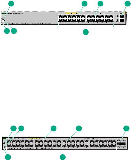
HPE OfficeConnect 1820 48G PoE+ (370W) Switch (J9984A)
1 |
2 |
3 |
4 |
5 |
|
|
|
|
|
|
|
|
|
|
|
|
|
|
|
|
|
|
|
|
|
|
|
|
|
|
|
|
|
|
|
|
|
|
|
|
|
|
|
|
|
|
|
|
|
|
|
|
|
|
|
|
|
|
|
|
|
|
|
|
|
|
|
|
|
|
|
|
|
|
|
|
|
|
|
|
|
|
|
|
|
|
|
|
|
|
|
|
|
|
|
|
|
|
|
|
|
|
|
|
|
|
|
|
|
|
|
|
|
|
|
|
|
|
|
|
|
|
|
|
|
|
|
|
|
|
|
|
|
|
|
|
|
|
|
|
|
|
|
|
|
|
|
|
|
|
|
|
|
|
|
|
|
|
|
|
|
|
|
|
|
|
|
|
|
|
|
|
|
|
|
|
|
|
|
|
|
|
|
|
|
|
|
|
|
|
|
|
|
|
|
|
|
|
|
|
|
|
|
|
|
|
|
|
|
|
|
|
|
|
|
|
|
|
|
|
|
|
|
|
|
|
|
|
|
|
|
|
|
|
|
|
|
|
|
|
|
|
|
|
|
|
|
|
|
|
|
|
|
|
|
|
|
|
|
|
|
|
|
|
|
|
|
|
|
|
|
|
|
|
|
|
|
|
|
|
|
|
|
|
|
|
|
|
|
|
|
|
|
|
|
|
|
|
|
|
|
|
|
|
|
|
|
|
|
|
|
|
|
|
|
|
|
|
|
|
|
|
|
|
|
|
|
|
|
|
|
|
|
|
|
|
|
|
|
|
|
|
|
|
|
|
|
|
|
|
|
|
|
|
7 |
|
|
|
|
|
|
|
|
|
|
6 |
|
|
|
|
|
|
|
|
|
|
|
|
|
|
|
|
|
|
|
|
|
|
|
|
|
|||||||||||||
1Power and Fault/Locator LEDs
2Mode button
3PoE+ ports 1-24
4Link/Act and Mode LEDs
5SFP slots
Switch overview 7

610/100/1000BASE-T RJ-45 ports
7Reset button
Network Ports
•Auto-sensing 10/100/1000BASE-T ports.
All these ports have the “Auto-MDIX” feature, which means that you can use either straight-through or crossover twisted-pair cables to connect any network devices to the switch.
•Power-over-Ethernet or PoE ports.
The 1820 PoE+ switches support the IEEE 802.3at standard, which allows IP telephones, wireless LAN Access Points, and other appliances to receive power as well as data over existing LAN cabling. For further information regarding PoE power, see the HPE Power over Ethernet (PoE/PoE+) Planning and Implementation Guide, which is on the Hewlett Packard Enterprise Web site at www.hpe.com/support/ hpesc.
•PoE PD port (1820 8G Switch only).
A network connection to the PoE PD port from a PoE PSE device powers on the switch.
•SFP slots for fiber or copper uplinks.
Using HPE SFPs, these products support optional network connectivity with the following speeds and technologies:
|
|
|
Transceiver Form- |
|
|
|
Factor and Connector1 |
Speed |
Technology |
Cabling |
SFP Connector |
|
|
|
|
100 Mbps |
100-FX |
Fiber (multimode) |
LC |
|
|
|
|
1 Gbps |
1000-T |
Copper (twisted-pair) |
RJ-45 |
|
|
|
|
|
1000-SX |
Fiber (multimode) |
LC |
|
|
|
|
|
1000-LX |
Fiber (multimode or |
LC |
|
|
single mode) |
|
|
|
|
|
1 For supported transceivers, visit www.hpe.com/support/hpesc.
• In the first textbox, type J4858 (for 100-Mb and Gigabit information).
• Select any of the products that display, then click Show selected items.
• Select Support Center. Then click Manuals and find the Transceiver Support Matrix.
For technical details of cabling and technology, see Cabling and Technology Information Specifications on page 37.
LEDs
The front panel of the switch provides status LEDs for system monitoring. The following table details the functions of the various indicators.
8Network Ports

LED |
State |
Meaning |
|
|
|
|
|
Power (green) |
On |
The switch is receiving power. |
|
|
|
|
|
|
Blinking* |
(1820 8G only) Power is available on the PoE In port (Port 1). |
|
|
|
|
|
|
Off |
The switch is NOT receiving power. |
|
|
|
|
|
Fault/Locator |
On |
On briefly after the switch is powered on or reset, at the beginning of |
|
(orange) |
|
switch self test. If the LED remains on, it indicates a detected hardware |
|
|
|
failure during the self test. |
|
|
|
|
|
|
Blinking** |
A fault has occurred on the switch or one of the switch ports. The Link LED |
|
|
|
for the port with the fault will blink simultaneously. |
|
|
|
|
|
|
Blinking*** |
The LED is used to locate a specific switch in an area full of switches. The |
|
|
|
LED blinks for 30 minutes when activated through the switch software. |
|
|
|
|
|
|
Off |
The normal state; indicates that there are no fault conditions on the switch. |
|
|
|
|
|
Link/Act(green) |
On |
The port is enabled and receiving a link indication from the connected |
|
|
|
device. |
|
|
|
|
|
|
Off |
One of these condition exists: |
|
|
|
• no active network cable is connected to the port |
|
|
|
• the port is not receiving link beat or sufficient light |
|
|
|
• Green Mode has been enabled. |
|
|
|
|
|
|
Blinking |
Indicates that there is network activity on the port.If the Link/Act LED is |
|
|
|
blinking simultaneously with the Fault/Locator LED, it indicates a fault on |
|
|
|
the port. The blinking behavior (1 second on, 1 second off) is the same as |
|
|
|
the Fault/Locator LED. |
|
|
|
|
|
SpdMode - Spd‡ |
On |
Indicates the port is operating at 1000 Mbps. |
|
(green) |
|
|
|
Flashing |
Indicates the port is operating at 100 Mbps. |
||
|
|||
|
|
|
|
|
Off |
Indicates the port is operating at 10 Mbps. |
|
|
|
|
|
Mode - PoE‡ |
On |
Indicates the Port LEDs are lit for ports that are providing PoE power to the |
|
(green) |
|
connected device. |
|
|
|
|
|
|
Blinking** |
There is an oversubscription condition (not enough PoE power available) |
|
|
|
or the port has experienced a fault condition for PoE delivery. |
|
|
|
|
* The blinking behavior is a 6 second on/off cycle; 5 seconds on, 1 second off. ** The blinking behavior is a 2 second on/off cycle; 1 second on, 1 second off.
*** The blinking behavior is a 4 second on/off cycle; 3 seconds on, 1 second off.
‡ (1820 PoE+ switches only) Press the Mode button in for PoE mode, leave the Mode button out for Spd mode.
Switch overview 9
Mode Button
The 1820 PoE+ switches have one Mode LED per port. The Mode LED shows either the port speed or the PoE status. In PoE mode, it shows whether the port is configured to provide PoE power. The operation of the Mode LED is controlled by the Mode select button. Press the Mode button in to select the PoE mode, or leave the button in its out position for Spd (speed) mode.
Reset button
The Reset button is used to restore Factory Default settings, or reset the switch while it is powered on.
•Resetting the Switch — Press and release the button. This action clears any temporary error conditions that may have occurred and executes the switch self test.
•Restoring Factory Default Configuration — Press and hold down for over 5 seconds, the switch will then complete its self test and begin operating with its configuration restored to the factory default settings. Any configuration changes you may have made through the web browser interface are removed.
Power Connector
The 1820 24G, 1820 24G PoE+, 1820 48G, and 1820 48G PoE+ Switches do not have a power switch, they are powered on when connected to an active AC power source. The switches automatically adjust to any voltage between 100-127 and 200-240 volts and either 50 or 60 Hz. There are no voltage range settings required.
The 1820 8G and 1820 8G PoE+ Switches do not have a power switch, they are powered on when the external AC/DC power adapter is connected to the switch and to a power source. The external AC/DC power adapter supplies 12 volts DC to the switch and automatically adjusts to any AC voltage between 100-240 volts and either 50 or 60 Hz. No voltage range settings are required.
The 1820 8G Switch can also be powered on by a PoE PD connection to Port 1.
Switch Features
The features of the 1820 Switches include:
•8, 24, or 48 auto-sensing 10/100/1000BASE-T RJ-45 ports.
•2 or 4 SFP slots for HPE SFP transceivers (1820 24G, 1820 24G-PoE+, 1820 48G, and 1820 48G-PoE+ Switches only)
•plug-and-play networking—all ports are enabled—just connect the network cables to active network devices and your switched network is operational.
•IEEE 802.3ab Auto MDI /MDI-X on all twisted-pair ports, meaning that all connections can be made using straight-through twisted-pair cables. Cross-over cables are not required, although they will also work. The pin operation of each port is automatically adjusted for the attached device: if the switch detects that a 10/100/1000 Mbps switch or hub is connected to the port, it configures the port as MDI; if the switch detects that a 10/100/1000 Mbps end-node device is connected to the port, it configures the port as MDI- X.
•all switches support IEEE 802.3az Energy Efficient Ethernet (EEE) features that reduce power consumption when connected with EEE-compliant client devices.
•automatic learning of MAC addresses in each switch’s 8K-address (8- and 24-port switches) or 16Kaddress (48-port switches) forwarding table.
•automatically negotiated full-duplex operation for all 10/100/1000BASE-T RJ-45 ports when connected to other auto-negotiating devices
•easy management of the switch through several available interfaces:
10 Mode Button
◦Web browser interface — an easy to use built-in graphical interface that can be accessed from common Web browsers.
◦Intelligent Management Center (iMC) — allows network administrators to discover and map the switches within their network and launch the built-in graphical interface from within iMC to configure the switches.
•support for up to 64 IEEE 802.1Q-compliant VLANs so you can divide the attached end nodes into logical groupings that fit your business needs.
•support for up to 16 trunks (48-port switches) so you can assign physical links to one logical link (trunk) that functions as a single, higher-speed link providing dramatically increased bandwidth.
•support for many advanced features to enhance network performance—for a description, see the
Management and Configuration Guide.
•download of new switch software for product bug fixes.
Switch overview 11

Installing the Switch
The 1820 Switches are easy to install. They come with an accessory kit that includes the brackets for mounting the switches in a standard 19-inch telco rack, in an equipment cabinet, and with rubber feet that can be attached so the switches can be securely located on a horizontal surface. The brackets are designed to allow mounting of the switches in a variety of locations and orientations. This chapter shows how to install the switches.
Included Parts
The following components ship with an 1820 Switch:
Documentation kit
•Quick Setup Guide
•Safety and Regulatory information
•Software License, Warranty, and Support information
•Accessory kits:
1820 8G and 1820 8G PoE+ Switch |
|
|
|
Kit number 5066-2232 |
Kit number 5066-0621 |
• two rack mounting brackets |
• three 3/4” (20-mm M4) screws for wall and under- |
• eight 8-mm M4 screws to attach the mounting |
table mounting |
brackets to the switch |
• three wall anchors |
• four 5/8-inch number 12-24 screws to attach the |
• cable tie for power cord |
switch to a rack |
|
• four rubber feet |
|
|
|
1820 24G, 1820 24G PoE+,and 1820 48G Switch |
1820 48G PoE+ Switch |
|
|
|
|
Kit number 5069-6535 |
Kit number 5069-5705 |
|
• two wall/table mounting brackets |
• two rack mounting brackets |
|
• eight 8-mm M4 screws to attach the mounting |
• eight 8-mm M4 screws to attach the mounting |
|
brackets to the switch |
brackets to the switch |
|
• four 5/8-inch number 12-24 screws to attach the |
• four 5/8-inch number 12-24 screws to attach the |
|
switch to a rack |
switch to a rack |
|
• four rubber feet |
• four rubber feet |
|
|
Kit number 5092-0769 |
|
|
• two wall/table mounting brackets |
|
|
|
|
• 1820 24and 48-port switch AC power cords, one of the following: |
|
|
|
|
|
Country/Region |
1820 24G, 1820 48G, |
1820 48G PoE+1 |
|
and 1820 24G PoE+ |
|
|
|
|
Argentina |
8120-6869 |
8120-8375 |
|
|
|
Australia/New Zealand |
8121-0834 |
8121-0857 |
Table Continued
12 Installing the Switch

Country/Region |
1820 24G, 1820 48G, |
1820 48G PoE+1 |
|
|
and 1820 24G PoE+ |
|
|
|
|
|
|
Brazil |
8121-1069 |
|
8121-1132 |
|
|
|
|
Chile |
8120-6980 |
|
8120-8389 |
|
|
|
|
China |
8120-8377 |
|
8121-1034 |
|
|
|
|
Continental Europe |
8120-6802 |
|
8120-5336 |
|
|
|
|
Denmark |
8120-6806 |
|
8120-5340 |
|
|
|
|
India |
8121-0780 |
|
8120-5341 |
|
|
|
|
Israel |
8121-1035 |
|
8121-1009 |
|
|
|
|
Japan |
8120-6804 |
|
8120-5342 |
|
|
|
|
Switzerland |
8120-6807 |
|
8120-5339 |
|
|
|
|
South Africa |
8121-0919 |
|
8120-5341 |
|
|
|
|
South Korea |
8120-6811 |
|
8120-5336 |
|
|
|
|
Taiwan |
8121-0964 |
|
8121-0967 |
|
|
|
|
Thailand |
8121-0673 |
|
8121-0671 |
|
|
|
|
UK/Hong Kong/Singapore/Malaysia |
8120-6809 |
|
8120-5334 |
|
|
|
|
US/Canada/Mexico |
8120-6805 |
|
8121-0973 |
|
|
|
|
1 The cord for the 1820 48G-PoE+ Switch supports a higher amperage and uses a C16 connector. |
|||
• The 1820 8G external AC/DC power adapters, one of the following: |
|
||
|
|
|
|
• Universal Inline AC/DC Power Adapter |
|
5066-1122 |
|
All countries/regions |
|
|
|
|
|
|
|
|
|
|
|
Power Cords for Inline AC/DC Power Adapter |
|
|
|
|
|
8121-0870 |
|
Australia/New Zealand |
|
|
|
|
|
|
|
Thailand |
|
8121-0664 |
|
|
|
|
|
China |
|
8120-8373 |
|
|
|
|
|
India |
|
8121-0702 |
|
|
|
|
|
Israel |
|
8120-6314 |
|
|
|
|
|
Japan |
|
8120-6316 |
|
|
|
|
|
South Africa |
|
8120-6317 |
|
|
|
|
|
South Korea |
|
8120-6314 |
|
|
|
|
|
Taiwan |
|
8121-0963 |
|
|
|
|
|
United Kingdom/Hong Kong/Singapore/Malaysia |
8120-8699 |
|
|
|
|
|
|
Brazil |
|
8121-1081 |
|
Table Continued
Installing the Switch 13

|
Argentina |
8120-8367 |
|
|
|
|
Chile |
8121-0514 |
|
|
|
• Wall Plug-in AC/DC Power Adapters(AC Power cords are not used) |
||
|
|
|
|
United States/Canada/Mexico |
5184-5863 |
|
|
|
|
Continental Europe/Denmark/Norway/Sweden/Switzerland/ |
5184-5864 |
|
Israel/Vietnam/Indonesia |
|
|
|
|
• The 1820 8G PoE+ external AC/DC power adapters and power cords, one of the following:
• Universal Inline AC/DC Power Adapter (model PA2) |
5066-2164 |
||
• All countries/regions |
|||
|
|||
|
|
|
|
|
Power Cords for Inline AC/DC Power Adapter |
|
|
|
|
|
|
|
Australia/New Zealand |
8121-0834 |
|
|
|
|
|
|
China |
8120-8377 |
|
|
|
|
|
|
Continental Europe |
8120-6802 |
|
|
|
|
|
|
Denmark |
8120-6806 |
|
|
|
|
|
|
India |
8121-0780 |
|
|
|
|
|
|
Israel |
8121-1035 |
|
|
|
|
|
|
Japan |
8120-6804 |
|
|
|
|
|
|
South Africa |
8121-0919 |
|
|
|
|
|
|
South Korea |
8120-6811 |
|
|
|
|
|
|
Switzerland |
8120-6807 |
|
|
|
|
|
|
Taiwan |
8121-0964 |
|
|
|
|
|
|
Thailand |
8121-0673 |
|
|
|
|
|
|
United Kingdom/Hong Kong/Singapore/Malaysia |
8120-6809 |
|
|
|
|
|
|
United States/Canada/Mexico |
8120-6805 |
|
|
|
|
|
|
Brazil |
8121-1069 |
|
|
|
|
|
|
Argentina |
8120-6869 |
|
|
|
|
|
|
Chile |
8120-6980 |
|
|
|
|
|
Japan Power Cord Warning
Installation precautions
Follow these precautions when installing the switch.
14 Installation precautions
Loading...