


 Loading...
HP 1810 Switch Series
Installation and Getting Started Guide
HP 1810-8 Switch (J9800A)
HP 1810-24 Switch (J9801A)
HP 1810-8G Switch (J9802A)
HP 1810-24G Switch (J9803A)
 In
In
Power over Ethernet PD

HP 1810 Switch Series
Installation and Getting Started Guide
© Copyright 2012 Hewlett-Packard Development Company, L.P.
The information contained herein is subject to change without notice.
This document contains proprietary information, which is protected by copyright. No part of this document may be photocopied, reproduced, or translated into another language without prior written consent of Hewlett-Packard.
Manual Part Number
5998-3207
December 2012
Applicable Products
HP 1810-8 Switch (J9800A)
HP 1810-24 Switch (J9801A)
HP 1810-8G Switch (J9802A)
HP 1810-24G Switch (J9803A)
Safety
Before installing and operating this product, please read the “Installation Precautions” in Chapter 2, “Installing the Switch”, and the safety statements in General Safety and Regulatory Information booklet included with the product.
Disclaimer
HEWLETT-PACKARD COMPANY MAKES NO WARRANTY OF ANY KIND WITH REGARD TO THIS MATERIAL, INCLUDING, BUT NOT LIMITED TO, THE IMPLIED WARRANTIES OF MERCHANTABILITY AND FITNESS FOR A PARTICULAR PURPOSE. Hewlett-Packard shall not be liable for errors contained herein or for incidental or consequential damages in connection with the furnishing, performance, or use of this material.
The only warranties for HP products and services are set forth in the express warranty statements accompanying such products and services. Nothing herein should be construed as constituting an additional warranty. HP shall not be liable for technical or editorial errors or omissions contained herein.
Hewlett-Packard assumes no responsibility for the use or reliability of its software on equipment that is not furnished by Hewlett-Packard.
Warranty
For the latest license and warranty information, visit www.hp.com/networking/support.
A copy of the specific warranty terms applicable to your Hewlett-Packard products and replacement parts can be obtained from your HP Sales and Service Office or authorized dealer.

Contents
1 Switch Overview
Switch Hardware Features . . . . . . . . . . . . . . . . . . . . . . . . . . . . . . . . . . . . . . . 1-2
Network Ports . . . . . . . . . . . . . . . . . . . . . . . . . . . . . . . . . . . . . . . . . . . . . . 1-3
LEDs . . . . . . . . . . . . . . . . . . . . . . . . . . . . . . . . . . . . . . . . . . . . . . . . . . . . . . 1-4
Reset Button . . . . . . . . . . . . . . . . . . . . . . . . . . . . . . . . . . . . . . . . . . . . . . . 1-5
Clear Button . . . . . . . . . . . . . . . . . . . . . . . . . . . . . . . . . . . . . . . . . . . . . . . 1-5
Power Connector . . . . . . . . . . . . . . . . . . . . . . . . . . . . . . . . . . . . . . . . . . . 1-5
Switch Features . . . . . . . . . . . . . . . . . . . . . . . . . . . . . . . . . . . . . . . . . . . . . . . . 1-6
2 Installing the Switch
Included Parts . . . . . . . . . . . . . . . . . . . . . . . . . . . . . . . . . . . . . . . . . . . . . . . . |
. 2-1 |
|
Installation Precautions . . . . . . . . . . . . . . . . . . . . . . . . . . . . . . . . . . . . . . |
2-3 |
|
Installation Procedure . . . . . . . . . . . . . . . . . . . . . . . . . . . . . . . . . . . . . . . . . . . |
2-4 |
|
1. |
Prepare the Installation Site . . . . . . . . . . . . . . . . . . . . . . . . . . . . . . . . |
2-5 |
2. |
Verify the Switch Passes Self Test . . . . . . . . . . . . . . . . . . . . . . . . . . . |
2-5 |
3. |
Mount the Switch . . . . . . . . . . . . . . . . . . . . . . . . . . . . . . . . . . . . . . . . . |
2-8 |
4. |
Connect the Switch to a Power Source . . . . . . . . . . . . . . . . . . . . . . |
2-13 |
5. |
Connect the Network Cables . . . . . . . . . . . . . . . . . . . . . . . . . . . . . . . |
2-14 |
6. |
Installing or Removing SFPs . . . . . . . . . . . . . . . . . . . . . . . . . . . . . . . |
2-15 |
3 Configuring the Switch
Initial Configuration . . . . . . . . . . . . . . . . . . . . . . . . . . . . . . . . . . . . . . . . . . . . . 3-1
Changing the PC’s IP Address . . . . . . . . . . . . . . . . . . . . . . . . . . . . . . . . . . . . . 3-2
Where to Go From Here . . . . . . . . . . . . . . . . . . . . . . . . . . . . . . . . . . . . . . . . . |
3-3 |
4 Troubleshooting
Basic Troubleshooting Tips . . . . . . . . . . . . . . . . . . . . . . . . . . . . . . . . . . . . . . |
4-1 |
Diagnosing with the LEDs . . . . . . . . . . . . . . . . . . . . . . . . . . . . . . . . . . . . . . . . 4-2 Diagnostic Tips: . . . . . . . . . . . . . . . . . . . . . . . . . . . . . . . . . . . . . . . . . . . . . 4-2
5

Testing the Switch by Resetting It . . . . . . . . . . . . . . . . . . . . . . . . . . . . . . . . . 4-4
Restoring to Factory Defaults . . . . . . . . . . . . . . . . . . . . . . . . . . . . . . . . . . . . . 4-4
HP Customer Support Services . . . . . . . . . . . . . . . . . . . . . . . . . . . . . . . . . . . 4-5
Before Calling Support . . . . . . . . . . . . . . . . . . . . . . . . . . . . . . . . . . . . . . . 4-5
A Specifications
Switch Specifications . . . . . . . . . . . . . . . . . . . . . . . . . . . . . . . . . . . . . . . . . . . A-1
Physical . . . . . . . . . . . . . . . . . . . . . . . . . . . . . . . . . . . . . . . . . . . . . . . . . . . A-1
Electrical . . . . . . . . . . . . . . . . . . . . . . . . . . . . . . . . . . . . . . . . . . . . . . . . . A-1
Environmental . . . . . . . . . . . . . . . . . . . . . . . . . . . . . . . . . . . . . . . . . . . . . A-2
Acoustics . . . . . . . . . . . . . . . . . . . . . . . . . . . . . . . . . . . . . . . . . . . . . . . . . A-2
Safety . . . . . . . . . . . . . . . . . . . . . . . . . . . . . . . . . . . . . . . . . . . . . . . . . . . . A-2
Standards . . . . . . . . . . . . . . . . . . . . . . . . . . . . . . . . . . . . . . . . . . . . . . . . . . . . . A-3
Cabling and Technology Information . . . . . . . . . . . . . . . . . . . . . . . . . . . . . A-4
Cabling Specifications . . . . . . . . . . . . . . . . . . . . . . . . . . . . . . . . . . . . . . A-4
Technology Distance Specifications . . . . . . . . . . . . . . . . . . . . . . . . . . . A-5
Mode Conditioning Patch Cord . . . . . . . . . . . . . . . . . . . . . . . . . . . . . . . . . . A-6 Installing the Patch Cord . . . . . . . . . . . . . . . . . . . . . . . . . . . . . . . . . . . . A-6
Twisted-Pair Cable/Connector Pin-Outs . . . . . . . . . . . . . . . . . . . . . . . . . . . |
A-8 |
Straight-through Twisted-Pair Cable for |
|
10 Mbps or 100 Mbps Network Connections . . . . . . . . . . . . . . . . . . . |
A-10 |
Crossover Twisted-Pair Cable for |
|
10 Mbps or 100 Mbps Network Connection . . . . . . . . . . . . . . . . . . . . |
A-11 |
Straight-Through Twisted-Pair Cable for |
|
1000 Mbps Network Connections . . . . . . . . . . . . . . . . . . . . . . . . . . . . |
A-12 |
B EMC Regulatory Statements
Regulatory Statements . . . . . . . . . . . . . . . . . . . . . . . . . . . . . . . . . . . . . . . . . . B-1
Index
6

1
Switch Overview
The HP 1810-8, 1810-24, 1810-8G, and 1810-24G Switches are multiport switches that can be used to build high-performance switched workgroup networks. These switches are store-and-forward devices that offer low latency for high-speed networking.
Throughout this manual, these switches will be referred to as the 1810-8
Switch, 1810-24 Switch, 1810-8G Switch, and the 1810-24G Switch.
■The 1810-8 Switch has 7 auto-sensing 10/100BASE-TX RJ-45 ports and one 10/100/1000BASE-T RJ-45 port (port 8).
■The 1810-24 Switch has 22 auto-sensing 10/100BASE-TX RJ-45 ports, two 10/100/1000BASE-T RJ-45 ports (ports 23 and 24), and two Small Form Factor Pluggable (SFP) slots for supported HP SFP (mini-GBIC) fiberoptic transceivers (ports 25 and 26).
■The 1810-8G Switch has 8 auto-sensing 10/100/1000BASE-T RJ-45 ports. Port 1 is a Power over Ethernet Powered Device (PoE PD) port. The switch can be powered by a network connection to port 1 from PoE power sourcing equipment (PSE), such as a PoE switch.
■The 1810-24G Switch has 24 auto-sensing 10/100/1000BASE-T RJ-45 ports and two SFP slots for supported HP SFP fiber-optic transceivers (ports 25 and 26).
These switches can be directly connected to computers, printers, and servers to provide dedicated bandwidth to those devices, and you can build a switched network infrastructure by connecting the switch to hubs, other switches, or routers. In addition, these switches offer network management capabilities.
1-1

Switch Overview
Switch Hardware Features
Switch Hardware Features
HP 1810-8 Switch (J9800A)
Link/Act and Speed LEDs
Power and
Fault LEDs
|
Locator LED |
|
|
|
|
|
|
|
|
|
|
|
10/100/1000BASE-T RJ-45 port1 |
|
|
|
|
|
10/100BASE-TX RJ-45 ports1 |
|
|
|
|
Reset and Clear buttons |
|
||
|
|
|
|
|
|
|
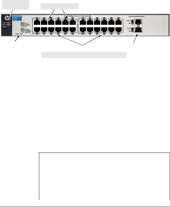
HP 1810-24 Switch (J9801A)
Power, Fault, and |
Link/Act and Speed LEDs |
Locator LEDs |
|
|
Reset and Clear buttons |
|
|
|
|
|
|
|
|
|
10/100BASE-TX RJ-45 ports1 |
|
10/100/1000BASE-T |
|
SFP slots |
|
|
|
|
|
|
|
|
|||
|
|
|
|
|
RJ-45 ports1 |
|
|
|
|
|
|
|
|
|
|
|
|
|
|
|
|
|
|
|
|
|
HP 1810-8G Switch (J9802A)
|
|
|
PoE PD port |
|
|
|
||
Link/Act and Speed LEDs |
|
|||||||
|
|
|
|
|
|
|
|
|
|
|
|
|
|
|
|
|
|
Power and |
|
|
|
|
|
|
|
|
Fault LEDs |
|
|
|
|
|
|
|
|
|
|
|
|
|
|
|
||
Locator LED |
|
|
|
|
|
|
|
|
|
|
|
|
|
|
|
|
|
|
|
Reset and Clear buttons |
|
|
|
10/100/1000BASE-T RJ-45 ports1 |
||
|
|
|
|
|
|
|
|
|
1 All RJ-45 ports have the Auto-MDIX feature.
1-2
Switch Overview
Switch Hardware Features
HP 1810-24G Switch (J9803A)
Power, Fault, and |
Link/Act and Speed LEDs |
Locator LEDs |
Reset and Clear buttons |
|
|
|
SFP slots |
10/100/1000BASE-T RJ-45 ports1 |
||||
|
|
|
|
|
1 All RJ-45 ports have the Auto-MDIX feature.
Network Ports
■Auto-sensing 10/100BASE-TX ports.
All these ports have the “Auto-MDIX” feature, which means that you can use either straight-through or crossover twisted-pair cables to connect any network devices to the switch.
■Auto-sensing 10/100/1000BASE-T ports.
All these ports have the “Auto-MDIX” feature, which means that you can use either straight-through or crossover twisted-pair cables to connect any network devices to the switch.
■PoE PD port (1810-8G Switch only)
A network connection to the PoE PD port from a PoE PSE device powers on the switch.
■SFP slots for fiber or copper uplinks.
This product supports optional network connectivity as follows:
Optional Network Connectivity, Speeds and Technologies
Speed |
Technology |
Cabling |
SFP ("mini-GBIC") |
|
|
|
Connector1 |
100 Mbps |
100-FX |
Fiber (multimode) |
LC |
|
|
|
|
|
1000-T |
Copper (twisted-pair) |
RJ-45 |
|
|
|
|
1 Gbps |
1000-SX |
Fiber (multimode) |
LC |
|
|
|
|
|
1000-LX |
Fiber (multimode or single mode) |
LC |
|
|
|
|
1-3

Switch Overview
Switch Hardware Features
1For supported transceivers, visit www.hp.com/networking/support.
–In the first textbox, type J4858 (for 100-Mb and Gigabit information).
–Select any of the products that display in the dropdown list. Click the Display selected button.
–Select Product support information. Then click Manuals and find the Transceiver Support Matrix.
For technical details of cabling and technologies see "Cabling and Technology Information" in Appendix A.
LEDs
The front panel of the switch provides status LEDs for system monitoring. The following table details the functions of the various indicators.
LED |
State |
Meaning |
|
|
|
Power |
On |
The switch is receiving power. |
(green) |
Off |
The switch is NOT receiving power. |
|
||
|
|
|
Fault |
On |
On briefly after the switch is powered on or reset, at the beginning of switch self |
(orange) |
|
test. If the LED remains on, it indicates a detected hardware failure during the self |
|
|
test. |
|
Blinking* |
A fault has occurred on the switch or one of the switch ports. The Link LED for the |
|
|
port with the fault will blink simultaneously. |
|
Off |
The normal state; indicates that there are no fault conditions on the switch. |
|
|
|
Locator |
Blinking** |
The Locator LED is used to locate a specific switch in an area full of switches. The |
(blue) |
|
LED blinks for 30 minutes when activated through the switch software. |
|
Off |
The Locator LED is disabled by default. |
|
|
|
PD |
On |
Power is available on the PoE In port (Port 1). |
(green) |
Blinking* |
Power is no longer available on the PoE In port. The switch is powered from the |
1810-8G Switch |
||
only |
|
external power adapter. The LED continues to blink until power is restored on the |
|
|
PoE In port or the switch reset. |
|
Off |
No power is available on the PoE In port. |
|
|
|
Link/Act |
On |
The port is enabled and receiving a link indication from the connected device. |
(green) |
Off |
One of these condition exists: |
|
||
|
|
• no active network cable is connected to the port |
|
|
• the port is not receiving link beat or sufficient light |
|
|
• Green Mode has been enabled. |
|
Blinking* |
Indicates that there is network activity on the port. |
|
|
|
1-4
Switch Overview
Switch Hardware Features
LED |
State |
Meaning |
|
|
|
Spd |
On |
Indicates the port is operating at 1000 Mbps. |
(green) |
Blinking |
Indicates the port is operating at 100 Mbps. |
|
||
|
Off |
Indicates the port is operating at 10 Mbps. |
|
|
|
* The blinking behavior is an on/off cycle once every 1.6 seconds, approximately. ** The blinking behavior is an on/off cycle once every 0.8 seconds, approximately.
Reset Button
This button is used to reset the switch while it is powered on. This action clears any temporary error conditions that may have occurred and executes the switch self test. The Reset button is also used with the Clear button to restore Factory Default settings.
Clear Button
This button is used for these purposes:
■Deleting Passwords - When pressed by itself for at least three seconds, the button deletes any switch console access passwords that you may have configured. Use this feature if you have misplaced the password and need console access.
This button is provided for your convenience, but its presence means that if you are concerned with the security of the switch configuration and operation, you should make sure the switch is installed in a secure location, such as a locked wiring closet.
■Restoring Factory Default Configuration - When pressed with the Reset button in a specific pattern, any configuration changes you may have made through the switch console, the web browser interface, and SNMP management are removed, and the factory default configuration is restored to the switch. For the specific method to restore the factory default configuration, see “Restoring the Factory Default Configuration” in chapter 4, “Troubleshooting” of this manual.
Power Connector
The 1810-24 and 1810-24G Switches do not have a power switch, they are powered on when connected to an active AC power source. The switches automatically adjust to any voltage between 100-127 and 200-240 volts and either 50 or 60 Hz. There are no voltage range settings required.
1-5

Switch Overview
Switch Features
The 1810-8 and 1810-8G Switches do not have a power switch, they are powered on when the external AC/DC power adapter is connected to the switch and to a power source. The external AC/DC power adapter supplies 12 volts DC to the switch and automatically adjusts to any AC voltage between 100-240 volts and either 50 or 60 Hz. No voltage range settings are required.
The 1810-8G Switch can also be powered on by a PoE PD connection to Port 1.
Switch Features
The features of the HP 1810 Switches include:
■7 or 22 auto-sensing 10/100BASE-TX RJ-45 ports.
■1, 2, 8, or 24 auto-sensing 10/100/1000BASE-T RJ-45 ports.
■2 SFP slots for HP mini-GBICs and SFP transceivers (1810-24 and 181024G Switches only)
■plug-and-play networking—all ports are enabled—just connect the network cables to active network devices and your switched network is operational.
■IEEE 802.3ab Auto MDI /MDI-X on all twisted-pair ports, meaning that all connections can be made using straight-through twisted-pair cables. Cross-over cables are not required, although they will also work. The pin operation of each port is automatically adjusted for the attached device: if the switch detects that a 10/100/1000 Mbps switch or hub is connected to the port, it configures the port as MDI; if the switch detects that a 10/ 100/1000 Mbps end-node device is connected to the port, it configures the port as MDI-X.
■all switches support IEEE 802.3az Energy Efficient Ethernet (EEE) features that reduce power consumption when connected with EEEcompliant client devices.
■automatic learning of the network addresses in each switch’s 8,000address forwarding table.
■automatically negotiated full-duplex operation for all 10/100/1000BASE-T RJ-45 ports when connected to other auto-negotiating devices
■easy management of the switch through several available interfaces:
•Web browser interface — an easy to use built-in graphical interface that can be accessed from common Web browsers.
1-6

Switch Overview
Switch Features
•ProCurve Manager (PCM) — allows network administrators to discover and map the switches within their network and launch the built-in graphical interface from within PCM to configure the switches.
■support for up to 128 IEEE 802.1Q-compliant VLANs so you can divide the attached end nodes into logical groupings that fit your business needs.
■support for up to 12 trunks so you can assign physical links to one logical link (trunk) that functions as a single, higher-speed link providing dramatically increased bandwidth.
■support for many advanced features to enhance network performance— for a description, see the Management and Configuration Guide.
■download of new switch software for product bug fixes.
1-7

Switch Overview
Switch Features
1-8

2
Installing the Switch
The HP 1810 Switches are easy to install. They come with an accessory kit that includes the brackets for mounting the switches in a standard 19-inch telco rack, in an equipment cabinet, and with rubber feet that can be attached so the switches can be securely located on a horizontal surface. The brackets are designed to allow mounting the switches in a variety of locations and orientations. This chapter shows how to install the switches.
Included Parts
The following components ship with an HP 1810 Switch:
■Documentation kit
•Quick Setup Guide
•Safety and Regulatory information
•Software License, Warranty, and Support information
■Accessory kits:
1810-24 and 1810-24G Switch |
1810-8 and 1810-8G Switch |
Kit number 5066-0620
•three 3/4” (20-mm M4) screws for wall and under-table mounting
•three wall anchors
Kit number 5066-2506
•two mounting brackets
•eight 8-mm M4 screws to attach the mounting brackets to the switch
•four 5/8-inch number 12-24 screws to attach the switch to a rack
Kit number 5064-4254
• four rubber feet
Kit number 5066-0621
•three 3/4” (20-mm M4) screws for wall and under-table mounting
•three wall anchors
•cable tie for power cord
Kit number 5064-4254
• four rubber feet
2-1

Installing the Switch
Included Parts
■1810-24 and 1810-24G Power cords, one of the following:
Australia/New Zealand |
8121-0833 |
China |
8120-8377 |
Continental Europe |
8120-6802 |
Denmark |
8120-6806 |
Japan |
8120-6804 |
Switzerland |
8120-6807 |
United Kingdom/Hong Kong/Singapore/Malaysia |
8120-8709 |
United States/Canada/Mexico |
8120-6805 |
South Africa |
8120-6808 |
South Korea |
8120-6802 |
India |
8121-0772 |
Israel |
8121-1035 |
Thailand |
8121-0667 |
Taiwan |
8121-0964 |
Argentina |
8120-6871 |
Brazil |
8121-1069 |
Chile |
8120-6979 |
■1810-8 and 1810-8G external AC/DC power adapters and power cords, one of the following:
• Universal Inline AC/DC Power Adapter |
|
All countries/regions |
5066-1122 |
Power Cords for Inline AC/DC Power Adapter |
|
Australia/New Zealand |
8121-0870 |
Thailand |
8121-0664 |
China |
8120-8373 |
India |
8121-0702 |
Israel |
8120-6314 |
Japan |
8120-6316 |
South Africa |
8120-6317 |
South Korea |
8120-8441 |
Taiwan |
8121-0963 |
United Kingdom/Hong Kong/Singapore/Malaysia |
8120-8699 |
Brazil |
8121-1081 |
Argentina |
8120-8367 |
Chile |
8121-0514 |
• Wall Plug-in AC/DC Power Adapters |
|
(AC Power cords are not used) |
|
United States/Canada/Mexico |
5184-5863 |
Continental Europe/Denmark/Norway/Sweden/Switzerland |
5184-5864 |
Japan Power Cord
Warning
2-2

W A R N I N G
C a u t i o n s
Installing the Switch
Included Parts
Installation Precautions
Follow these precautions when installing the switch.
■The rack or cabinet should be adequately secured to prevent it from becoming unstable and/or falling over.
Devices installed in a rack or cabinet should be mounted as low as possible, with the heaviest devices at the bottom and progressively lighter devices installed above.
■When wall mounting, to meet national and international safety requirements, wall mount with the network ports facing up. The side vents cannot be placed up or downward.
■When installing the switch, the AC outlet should be located near the
switch and should be easily accessible in case the switch must be powered off.
■Ensure that the AC power source circuits are properly grounded.
■Use only the AC/DC power adapter and power cord (if applicable), supplied with the switch. Use of other adapters or power cords, including those that came with other HP Networking products, may result in damage to the equipment.
For those switches that use a power cord, if your installation requires a different power cord than the one supplied with the switch, be sure to use a power cord displaying the mark of the safety agency the defines the regulations for power cords in your country. The mark is your assurance that the power cord can be used safely with the switch.
■Ensure the switch does not overload the power circuits, wiring, and overcurrent protection. To determine the possibility of overloading the supply circuits, add together the ampere ratings of all devices installed on the same circuit as the switch and compare the total with the rating limit for the circuit. The maximum ampere ratings are usually printed on the devices near the AC power connectors.
■Do not install the switch in an environment where the operating ambient temperature might exceed 40 °C (104 °F).
■Ensure the air flow around the sides of the switch is not restricted.
2-3

Installing the Switch
Installation Procedure
Installation Procedure
These steps summarize your switch installation. The rest of this chapter provides details on these steps.
1.Prepare the installation site (page 2-5). Make sure the physical environment into which you will be installing the switch is properly prepared, including having the correct network cabling ready to connect to the switch and having an appropriate location for the switch. See page 2-5 for some installation precautions.
2.Verify the switch passes self test (page 2-5). Plug the switch into a power source and observe that the LEDs on the switch’s front panel indicate correct switch operation.
3.Mount the switch (page 2-8). The 1810-24 and 1810-24G Switches can be mounted in a 19-inch telco rack, in an equipment cabinet, on a wall, under a table, or on a horizontal surface. The 1810-8 and 1810-8G Switches can be mounted on a wall, under a table, or on a horizontal surface.
4.Connect power to the switch (page 2-13). Once the switch is mounted, plug it into the main power source.
5.Connect the network devices (page 2-14). Using the appropriate network cables, connect the network devices to the switch ports.
6.(Optional) Install SFP transceivers (page 2-5). The 1810-24 and 181024G Switches have two slots for installing SFP transceivers (mini-GBICs). Depending on where you install the switch, it may be easier to install the SFPs first. SFPs can be hot swapped—they can be installed or removed while the switch is powered on.
At this point, your switch is fully installed. See the rest of this chapter if you need more detailed information on any of these installation steps.
2-4
Loading...