


 Loading...
LASERJET PROFESSIONAL P1560 and P1600
SERIES PRINTER
Service Manual
www.hp.com/support/ljp1560series
www.hp.com/support/ljp1600series

HP LaserJet Professional P1560 and
P1600 Series Printer
Service Manual
Copyright and License
© 2010 Copyright Hewlett-Packard
Development Company, L.P.
Reproduction, adaptation, or translation without prior written permission is prohibited, except as allowed under the copyright laws.
The information contained herein is subject to change without notice.
The only warranties for HP products and services are set forth in the express warranty statements accompanying such products and services. Nothing herein should be construed as constituting an additional warranty. HP shall not be liable for technical or editorial errors or omissions contained herein.
Part number: CE663-90939
Edition 1, 4/2010
Trademark Credits
Microsoft®, Windows®, Windows® XP, and Windows Vista® are U.S. registered trademarks of Microsoft Corporation.

Conventions used in this guide
TIP: Tips provide helpful hints or shortcuts.
 NOTE: Notes provide important information to explain a concept or to complete a task.
 CAUTION: Cautions indicate procedures that you should follow to avoid losing data or damaging the product.
 WARNING! Warnings alert you to specific procedures that you should follow to avoid personal injury, catastrophic loss of data, or extensive damage to the product.
ENWW |
iii |
iv Conventions used in this guide |
ENWW |

Table of contents
1 Theory of operation ........................................................................................................................................ |
1 |
Basic operation ..................................................................................................................................... |
2 |
Major product systems ......................................................................................................... |
2 |
Product block diagram ......................................................................................................... |
2 |
Sequence of operation ......................................................................................................... |
3 |
Normal sequence of operation ............................................................................ |
3 |
Formatter-control system ..................................................................................................................... |
4 |
Sleep mode .......................................................................................................................... |
4 |
Input/output .......................................................................................................................... |
4 |
CPU ..................................................................................................................................... |
4 |
Memory ................................................................................................................................ |
4 |
Firmware ............................................................................................................. |
5 |
Memory use ........................................................................................................ |
5 |
PJL overview ....................................................................................................................... |
5 |
LEDM overview .................................................................................................................... |
5 |
ACL overview ....................................................................................................................... |
5 |
Control panel ....................................................................................................................... |
6 |
Engine-control system .......................................................................................................................... |
7 |
Motors, fans, clutches, solenoids, switches, and sensors ................................................... |
8 |
DC controller operations .................................................................................................... |
13 |
Fuser-control circuit ........................................................................................................... |
15 |
Fuser failure detection ....................................................................................... |
16 |
Fuser temperature control ................................................................................. |
17 |
Fuser protective function ................................................................................... |
18 |
Pressure roller cleaning .................................................................................... |
18 |
Low-voltage power supply ................................................................................................. |
19 |
Overcurrent/overvoltage protection ................................................................... |
20 |
High-voltage power supply ................................................................................................ |
21 |
Laser/scanner system ........................................................................................................ |
22 |
Laser failure detection ....................................................................................... |
23 |
Image-formation system ..................................................................................................................... |
24 |
Electrophotographic process ............................................................................................. |
24 |
Image formation process ................................................................................................... |
26 |
Latent-image formation stage ........................................................................... |
27 |
ENWW |
v |
Primary charging .............................................................................. |
27 |
Laser beam exposure ....................................................................... |
27 |
Developing stage .............................................................................................. |
28 |
Print cartridge ................................................................................... |
28 |
Transfer stage ................................................................................................... |
29 |
Fusing stage ..................................................................................... |
29 |
Cleaning stage .................................................................................. |
30 |
Pickup, feed, and delivery system ...................................................................................................... |
31 |
Photo sensors and switches .............................................................................................. |
32 |
Main-input tray or priority input slot .................................................................................................... |
34 |
Jam detection .................................................................................................................... |
34 |
2 Removal and replacement ........................................................................................................................... |
35 |
Introduction ......................................................................................................................................... |
36 |
Removal and replacement strategy ................................................................................................... |
36 |
Electrostatic discharge ....................................................................................................................... |
37 |
Required tools ................................................................................................................................... |
37 |
Before performing service .................................................................................................................. |
37 |
After performing service ..................................................................................................................... |
38 |
Post-service test ................................................................................................................................. |
38 |
Print-quality test ................................................................................................................. |
38 |
Parts removal order ............................................................................................................................ |
39 |
Pickup roller ........................................................................................................................................ |
40 |
Separation pad ................................................................................................................................... |
41 |
Transfer roller ..................................................................................................................................... |
42 |
Covers ................................................................................................................................................ |
43 |
Main-input tray ................................................................................................................... |
43 |
Output bin tray extension ................................................................................................... |
44 |
Left cover, simplex product ................................................................................................ |
45 |
Remove the left cover, simplex product ............................................................ |
45 |
Left cover, duplex product ................................................................................................. |
47 |
Remove the left cover, duplex product .............................................................. |
47 |
Right cover, simplex product ............................................................................................. |
50 |
Remove the right cover, simplex product .......................................................... |
50 |
Right cover, duplex product ............................................................................................... |
52 |
Remove the right cover, duplex product ........................................................... |
52 |
Duplex door, duplex product .............................................................................................. |
55 |
Duplex frame, duplex product ............................................................................................ |
56 |
Remove the duplex frame ................................................................................. |
56 |
Cartridge door .................................................................................................................... |
57 |
Control panel ..................................................................................................................... |
59 |
Front cover ......................................................................................................................... |
61 |
Remove the front cover ..................................................................................... |
61 |
vi |
ENWW |
Rear cover, simplex product .............................................................................................. |
63 |
Remove the rear cover, simplex product .......................................................... |
63 |
Face-down cover ............................................................................................................... |
65 |
Remove the face-down cover ........................................................................... |
65 |
Main assemblies ................................................................................................................................. |
67 |
Formatter PCA ................................................................................................................... |
67 |
Laser/scanner assembly .................................................................................................... |
68 |
Remove the laser/scanner assembly ................................................................ |
68 |
Reinstall the laser/scanner assembly ................................................................ |
71 |
Pickup assembly ................................................................................................................ |
72 |
Remove the pickup assembly ........................................................................... |
72 |
Reinstall the pickup assembly ........................................................................... |
78 |
Fuser .................................................................................................................................. |
80 |
Remove the fuser .............................................................................................. |
80 |
Reinstall the fuser ............................................................................................. |
86 |
Main motor ......................................................................................................................... |
87 |
Remove the main motor .................................................................................... |
87 |
Reinstall the main-motor drive belt .................................................................... |
92 |
Pickup solenoid .................................................................................................................. |
93 |
Remove the pickup solenoid ............................................................................. |
93 |
Engine controller PCA ....................................................................................................... |
97 |
Remove the engine controller PCA ................................................................... |
97 |
Reinstall the engine controller PCA ................................................................ |
102 |
Duplex-reverse solenoid, duplex product ........................................................................ |
104 |
Remove the duplex-reverse solenoid .............................................................. |
104 |
Main fan, duplex product ................................................................................................. |
107 |
Remove the main fan ...................................................................................... |
107 |
Reinstall the main fan ...................................................................................... |
109 |
Duplex-connector PCA, duplex product ........................................................................... |
110 |
Remove the duplex-connector PCA ................................................................ |
110 |
3 Solve problems ........................................................................................................................................... |
113 |
Solve problems checklist .................................................................................................................. |
114 |
Troubleshooting process .................................................................................................................. |
116 |
Determine the problem source ....................................................................................... |
116 |
Power subsystem ............................................................................................................ |
117 |
Power-on checks ............................................................................................. |
117 |
Tools for troubleshooting .................................................................................................................. |
118 |
Individual component diagnostics .................................................................................... |
118 |
Engine diagnostics .......................................................................................... |
118 |
Engine-test button .......................................................................... |
118 |
Components tests ........................................................................................... |
119 |
Drum rotation functional check ...................................................... |
119 |
ENWW |
vii |
Half self-test functional check ......................................................... |
119 |
Diagrams ......................................................................................................................... |
120 |
Plug/jack locations .......................................................................................... |
120 |
Location of connectors .................................................................................... |
121 |
Locations of major components ...................................................................... |
122 |
General timing charts ...................................................................................... |
125 |
General circuit diagram ................................................................................... |
126 |
Internal print-quality test pages ........................................................................................ |
127 |
Cleaning page ................................................................................................. |
127 |
Configuration page .......................................................................................... |
127 |
Print-quality troubleshooting tools .................................................................................... |
128 |
Repetitive defect ruler ..................................................................................... |
128 |
Interpret control-panel light patterns ................................................................................ |
128 |
Clear jams ........................................................................................................................................ |
133 |
Common causes of jams ................................................................................................. |
133 |
Jam locations ................................................................................................................... |
133 |
Clear jams from the input trays ........................................................................................ |
134 |
Clear jams from the duplexer ........................................................................................... |
136 |
Clear jams from the output areas .................................................................................... |
138 |
Clear jams from inside the product .................................................................................. |
139 |
Solve repeated jams ........................................................................................................ |
141 |
Change jam recovery ...................................................................................................... |
142 |
Solve paper-handling problems ........................................................................................................ |
143 |
Solve image-quality problems .......................................................................................................... |
144 |
Image defect table ........................................................................................................... |
144 |
Light print or faded .......................................................................................... |
144 |
Toner specks ................................................................................................... |
144 |
Dropouts .......................................................................................................... |
145 |
Vertical lines .................................................................................................... |
145 |
Gray background ............................................................................................. |
145 |
Toner smear .................................................................................................... |
146 |
Loose toner ..................................................................................................... |
146 |
Vertical repetitive defects ................................................................................ |
146 |
Misformed characters ...................................................................................... |
146 |
Page skew ....................................................................................................... |
147 |
Curl or wave .................................................................................................... |
147 |
Wrinkles or creases ......................................................................................... |
147 |
Toner scatter outline ....................................................................................... |
148 |
Moisture .......................................................................................................... |
148 |
Change print density ........................................................................................................ |
149 |
Clean the product ............................................................................................................................. |
150 |
Clean the pickup roller ..................................................................................................... |
150 |
Clean the paper path ....................................................................................................... |
151 |
Clean the print-cartridge area .......................................................................................... |
153 |
viii |
ENWW |
Clean the exterior ............................................................................................................ |
154 |
Solve performance problems ........................................................................................................... |
155 |
Solve connectivity problems ............................................................................................................. |
156 |
Solve direct-connect problems ........................................................................................ |
156 |
Solve network problems .................................................................................................. |
156 |
Service mode functions .................................................................................................................... |
158 |
Product resets .................................................................................................................. |
158 |
Product updates ............................................................................................................................... |
158 |
Firmware updates ............................................................................................................ |
158 |
4 Parts and diagrams ..................................................................................................................................... |
159 |
Order parts by authorized service providers .................................................................................... |
160 |
Order replacement parts .................................................................................................. |
160 |
Related documentation and software .............................................................................. |
160 |
Supplies part numbers ..................................................................................................... |
160 |
Customer self repair parts ............................................................................................... |
161 |
Service parts .................................................................................................................... |
161 |
Whole-unit replacement part numbers ............................................................................. |
161 |
How to use the parts lists and diagrams .......................................................................................... |
162 |
Assembly locations ........................................................................................................................... |
163 |
Base product (no optional trays or accessories) .............................................................. |
163 |
Covers .............................................................................................................................................. |
164 |
Simplex model ................................................................................................................. |
164 |
Duplex model ................................................................................................................... |
166 |
Internal assemblies .......................................................................................................................... |
168 |
Internal assemblies (1 of 3) ............................................................................................. |
168 |
Internal assemblies (2 of 3) ............................................................................................. |
170 |
Internal assemblies (3 of 3) ............................................................................................. |
172 |
PCAs ................................................................................................................................................ |
174 |
Alphabetical parts list ....................................................................................................................... |
176 |
Numerical parts list ........................................................................................................................... |
179 |
Appendix A Service and support ................................................................................................................. |
183 |
Hewlett-Packard limited warranty statement .................................................................................... |
184 |
HP's Premium Protection Warranty: LaserJet print cartridge limited warranty statement ................ |
185 |
End User License Agreement .......................................................................................................... |
186 |
Customer self-repair warranty service .............................................................................................. |
188 |
Customer support ............................................................................................................................. |
188 |
Repack the product .......................................................................................................................... |
189 |
Service information form .................................................................................................................. |
190 |
Appendix B Specifications ............................................................................................................................ |
191 |
Physical specifications ..................................................................................................................... |
192 |
ENWW |
ix |
Power consumption .......................................................................................................................... |
192 |
Acoustic specifications ..................................................................................................................... |
192 |
Environmental specifications ............................................................................................................ |
193 |
Appendix C Regulatory information ............................................................................................................ |
195 |
FCC regulations ............................................................................................................................... |
196 |
Declaration of conformity .................................................................................................................. |
197 |
Certificate of Volatility ....................................................................................................................... |
198 |
Safety statements ............................................................................................................................. |
200 |
Laser safety ..................................................................................................................... |
200 |
Canadian DOC regulations .............................................................................................. |
200 |
VCCI statement (Japan) .................................................................................................. |
200 |
Power cord instructions ................................................................................................... |
200 |
Power cord statement (Japan) ......................................................................................... |
200 |
EMC statement (Korea) ................................................................................................... |
200 |
Laser statement for Finland ............................................................................................. |
201 |
GS statement (Germany) ................................................................................................. |
201 |
Substances Table (China) ............................................................................................... |
202 |
Restriction on Hazardous Substances statement (Turkey) ............................................. |
202 |
Index ................................................................................................................................................................. |
203 |
x |
ENWW |

List of tables
Table 1-1 Sequence of operation ....................................................................................................................... |
3 |
|
Table 1-2 |
Motors ................................................................................................................................................ |
8 |
Table 1-3 |
Fans ................................................................................................................................................... |
9 |
Table 1-4 Solenoids and clutches .................................................................................................................... |
10 |
|
Table 1-5 |
Switches ........................................................................................................................................... |
11 |
Table 1-6 |
Sensors ............................................................................................................................................ |
11 |
Table 1-7 DC controller controlled components ............................................................................................... |
13 |
|
Table 1-8 Photo sensors, motor, and solenoid ................................................................................................ |
32 |
|
Table 3-1 Basic problem solving .................................................................................................................... |
114 |
|
Table 3-2 |
Status-light legend ......................................................................................................................... |
128 |
Table 3-3 |
Control-panel lights ........................................................................................................................ |
129 |
Table 4-1 Order parts, accessories, and supplies .......................................................................................... |
160 |
|
Table 4-2 Related documentation and software ............................................................................................ |
160 |
|
Table 4-3 Supplies part numbers ................................................................................................................... |
160 |
|
Table 4-4 Customer replaceable units (CRU) kit part numbers ..................................................................... |
161 |
|
Table 4-5 Whole-unit replacement part numbers ........................................................................................... |
161 |
|
Table 4-6 |
Base product .................................................................................................................................. |
163 |
Table 4-7 |
Simplex model ................................................................................................................................ |
165 |
Table 4-8 |
Duplex model ................................................................................................................................. |
167 |
Table 4-9 Internal assemblies (1 of 3) ............................................................................................................ |
169 |
|
Table 4-10 Internal assemblies (2 of 3) .......................................................................................................... |
171 |
|
Table 4-11 Internal assemblies (3 of 3) .......................................................................................................... |
173 |
|
Table 4-12 |
PCAs ............................................................................................................................................ |
175 |
Table 4-13 Alphabetical parts list ................................................................................................................... |
176 |
|
Table 4-14 Numerical parts list ....................................................................................................................... |
179 |
|
Table B-1 |
Physical specifications1 .................................................................................................................. |
192 |
Table B-2 HP LaserJet Professional P1560 and P1600 Printer series (average in watts)123 ......................... |
192 |
|
Table B-3 HP LaserJet Professional P1560 and P1600 Printer series12 ........................................................ |
192 |
|
Table B-4 |
Environmental specifications ......................................................................................................... |
193 |
ENWW |
xi |
xii |
ENWW |

List of figures
Figure 1-1 Product block diagram ...................................................................................................................... |
2 |
|
Figure 1-2 |
Engine-control system ...................................................................................................................... |
7 |
Figure 1-3 |
Motors ............................................................................................................................................... |
8 |
Figure 1-4 |
Fans .................................................................................................................................................. |
9 |
Figure 1-5 Solenoids and clutches ................................................................................................................... |
10 |
|
Figure 1-6 |
Switches .......................................................................................................................................... |
11 |
Figure 1-7 |
Sensors ........................................................................................................................................... |
11 |
Figure 1-8 DC controller block diagram ............................................................................................................ |
13 |
|
Figure 1-9 Fuser control circuit ......................................................................................................................... |
15 |
|
Figure 1-10 Fuser-heater control circuit ........................................................................................................... |
17 |
|
Figure 1-11 Low-voltage power supply (LVPS) ................................................................................................ |
19 |
|
Figure 1-12 High-voltage power supply ............................................................................................................ |
21 |
|
Figure 1-13 |
Laser/scanner system ................................................................................................................... |
22 |
Figure 1-14 Electrophotographic process block diagram (1 of 2) .................................................................... |
24 |
|
Figure 1-15 Electrophotographic process block diagram (2 of 2) .................................................................... |
25 |
|
Figure 1-16 Image formation process .............................................................................................................. |
26 |
|
Figure 1-17 |
Primary charging ........................................................................................................................... |
27 |
Figure 1-18 Laser beam exposure ................................................................................................................... |
27 |
|
Figure 1-19 |
Print cartridge ................................................................................................................................ |
28 |
Figure 1-20 |
Transfer ......................................................................................................................................... |
29 |
Figure 1-21 |
Separation ..................................................................................................................................... |
29 |
Figure 1-22 |
Fusing ........................................................................................................................................... |
30 |
Figure 1-23 |
Drum cleaning ............................................................................................................................... |
30 |
Figure 1-24 Pickup, feed, and delivery system block diagram ......................................................................... |
31 |
|
Figure 1-25 Photo sensors, motor, and solenoid ............................................................................................. |
32 |
|
Figure 2-1 Phillips and pozidrive screwdriver comparison ............................................................................... |
37 |
|
Figure 2-2 Parts removal order ........................................................................................................................ |
39 |
|
Figure 2-3 Remove the pickup roller (1 of 2) .................................................................................................... |
40 |
|
Figure 2-4 Remove the pickup roller (2 of 2) .................................................................................................... |
40 |
|
Figure 2-5 Remove the separation pad assembly ........................................................................................... |
41 |
|
Figure 2-6 Remove the transfer roller .............................................................................................................. |
42 |
|
Figure 2-7 Remove the tray .............................................................................................................................. |
43 |
|
Figure 2-8 Remove the output bin tray extension ............................................................................................ |
44 |
|
Figure 2-9 Remove the left cover, simplex product (1 of 4) ............................................................................. |
45 |
|
ENWW |
xiii |
Figure 2-10 Remove the left cover, simplex product (2 of 4) ........................................................................... |
45 |
Figure 2-11 Remove the left cover, simplex product (3 of 4) ........................................................................... |
46 |
Figure 2-12 Remove the left cover, simplex product (4 of 4) ........................................................................... |
46 |
Figure 2-13 Remove the left cover, duplex product (1 of 5) ............................................................................. |
47 |
Figure 2-14 Remove the left cover, duplex product (2 of 5) ............................................................................. |
47 |
Figure 2-15 Remove the left cover, duplex product (3 of 5) ............................................................................. |
48 |
Figure 2-16 Remove the left cover, duplex product (4 of 5) ............................................................................. |
48 |
Figure 2-17 Remove the left cover, duplex product (5 of 5) ............................................................................. |
49 |
Figure 2-18 Remove the right cover, simplex product (1 of 4) ......................................................................... |
50 |
Figure 2-19 Remove the right cover, simplex product (2 of 4) ......................................................................... |
50 |
Figure 2-20 Remove the right cover, simplex product (4 of 4) ......................................................................... |
51 |
Figure 2-21 Remove the right cover, duplex product (1 of 5) ........................................................................... |
52 |
Figure 2-22 Remove the right cover, duplex product (2 of 5) ........................................................................... |
52 |
Figure 2-23 Remove the right cover, duplex product (3 of 5) ........................................................................... |
53 |
Figure 2-24 Remove the right cover, duplex product (4 of 5) ........................................................................... |
53 |
Figure 2-25 Remove the right cover, duplex product (5 of 5) ........................................................................... |
54 |
Figure 2-26 Remove the duplex door, duplex product ..................................................................................... |
55 |
Figure 2-27 Remove the duplex frame (1 of 2) ................................................................................................ |
56 |
Figure 2-28 Remove the duplex frame (2 of 2) ................................................................................................ |
56 |
Figure 2-29 Remove the cartridge door (1 of 3) ............................................................................................... |
57 |
Figure 2-30 Remove the cartridge door (2 of 3) ............................................................................................... |
57 |
Figure 2-31 Remove the cartridge door (3 of 3) ............................................................................................... |
58 |
Figure 2-32 Remove the control panel (1 of 3) ................................................................................................ |
59 |
Figure 2-33 Remove the control panel (2 of 3) ................................................................................................ |
59 |
Figure 2-34 Remove the control panel (3 of 3) ................................................................................................ |
60 |
Figure 2-35 Remove the front cover (1 of 3) .................................................................................................... |
61 |
Figure 2-36 Remove the front cover (2 of 3) .................................................................................................... |
62 |
Figure 2-37 Remove the front cover (3 of 3) .................................................................................................... |
62 |
Figure 2-38 Remove the rear cover, simplex product (1 of 3) .......................................................................... |
63 |
Figure 2-39 Remove the rear cover, simplex product (2 of 3) .......................................................................... |
64 |
Figure 2-40 Remove the rear cover, simplex product (2 of 3) .......................................................................... |
64 |
Figure 2-41 Remove the face-down cover (1 of 2) ........................................................................................... |
65 |
Figure 2-42 Remove the face-down cover (2 of 2) ........................................................................................... |
66 |
Figure 2-43 Remove the formatter PCA (1 of 2) .............................................................................................. |
67 |
Figure 2-44 Remove the formatter PCA (2 of 2) .............................................................................................. |
67 |
Figure 2-45 Remove the laser/scanner assembly (1 of 5) ............................................................................... |
68 |
Figure 2-46 Remove the laser/scanner assembly (2 of 5) ............................................................................... |
69 |
Figure 2-47 Remove the laser/scanner assembly (3 of 5) ............................................................................... |
69 |
Figure 2-48 Remove the laser/scanner assembly (4 of 5) ............................................................................... |
70 |
Figure 2-49 Remove the laser/scanner assembly (5 of 5) ............................................................................... |
70 |
Figure 2-50 Reinstall the laser/scanner assembly ........................................................................................... |
71 |
Figure 2-51 Remove the pickup assembly (1 of 10) ........................................................................................ |
72 |
Figure 2-52 Remove the pickup assembly (2 of 10) ........................................................................................ |
73 |
Figure 2-53 Remove the pickup assembly (3 of 10) ........................................................................................ |
73 |
xiv |
ENWW |
Figure 2-54 Remove the pickup assembly (4 of 10) ........................................................................................ |
74 |
Figure 2-55 Remove the pickup assembly (5 of 10) ........................................................................................ |
74 |
Figure 2-56 Remove the pickup assembly (6 of 10) ........................................................................................ |
75 |
Figure 2-57 Remove the pickup assembly (7 of 10) ........................................................................................ |
75 |
Figure 2-58 Remove the pickup assembly (8 of 10) ........................................................................................ |
76 |
Figure 2-59 Remove the pickup assembly (9 of 10) ........................................................................................ |
76 |
Figure 2-60 Remove the pickup assembly (10 of 10) ...................................................................................... |
77 |
Figure 2-61 Reinstall the pickup assembly (1 of 4; correct ground spring position) ......................................... |
78 |
Figure 2-62 Reinstall the pickup assembly (2 of 4; incorrect ground spring position) ...................................... |
78 |
Figure 2-63 Reinstall the pickup assembly (3 of 4; lift plate in raised position) ................................................ |
79 |
Figure 2-64 Reinstall the pickup assembly (4 of 4; lift plate in lowered position) ............................................. |
79 |
Figure 2-65 Remove the fuser (1 of 10) ........................................................................................................... |
80 |
Figure 2-66 Remove the fuser (2 of 10) ........................................................................................................... |
81 |
Figure 2-67 Remove the fuser (3 of 10) ........................................................................................................... |
81 |
Figure 2-68 Remove the fuser (4 of 10) ........................................................................................................... |
82 |
Figure 2-69 Remove the fuser (5 of 10) ........................................................................................................... |
82 |
Figure 2-70 Remove the fuser (6 of 10) ........................................................................................................... |
83 |
Figure 2-71 Remove the fuser (7 of 10) ........................................................................................................... |
83 |
Figure 2-72 Remove the fuser (8 of 10) ........................................................................................................... |
84 |
Figure 2-73 Remove the fuser (9 of 10) ........................................................................................................... |
84 |
Figure 2-74 Remove the fuser (10 of 10) ......................................................................................................... |
85 |
Figure 2-75 Reinstall the fuser; correct wire harness installation ..................................................................... |
86 |
Figure 2-76 Reinstall the fuser; incorrect wire harness installation .................................................................. |
86 |
Figure 2-77 Remove the main motor (1 of 9) ................................................................................................... |
87 |
Figure 2-78 Remove the main motor (2 of 9) ................................................................................................... |
88 |
Figure 2-79 Remove the main motor (3 of 9) ................................................................................................... |
88 |
Figure 2-80 Remove the main motor (4 of 9) ................................................................................................... |
89 |
Figure 2-81 Remove the main motor (5 of 9) ................................................................................................... |
89 |
Figure 2-82 Remove the main motor (6 of 9) ................................................................................................... |
90 |
Figure 2-83 Remove the main motor (7 of 9) ................................................................................................... |
90 |
Figure 2-84 Remove the main motor (8 of 9) ................................................................................................... |
91 |
Figure 2-85 Remove the main motor (9 of 9) ................................................................................................... |
91 |
Figure 2-86 Main-motor drive belt: correctly installed ...................................................................................... |
92 |
Figure 2-87 Main-motor drive belt: incorrectly installed .................................................................................... |
92 |
Figure 2-88 Remove the pickup solenoid (1 of 7) ............................................................................................ |
93 |
Figure 2-89 Remove the pickup solenoid (2 of 7) ............................................................................................ |
94 |
Figure 2-90 Remove the pickup solenoid (3 of 7) ............................................................................................ |
94 |
Figure 2-91 Remove the pickup solenoid (4 of 7) ............................................................................................ |
95 |
Figure 2-92 Remove the solenoid (5 of 7) ........................................................................................................ |
95 |
Figure 2-93 Remove the pickup solenoid (6 of 7) ............................................................................................ |
96 |
Figure 2-94 Remove the pickup solenoid (7 of 7) ............................................................................................ |
96 |
Figure 2-95 Remove the engine controller PCA (1 of 9) .................................................................................. |
97 |
Figure 2-96 Remove the engine controller PCA (2 of 9) .................................................................................. |
98 |
Figure 2-97 Remove the engine controller PCA (3 of 9) .................................................................................. |
98 |
ENWW |
xv |
Figure 2-98 Remove the engine controller PCA (4 of 9) .................................................................................. |
99 |
|
Figure 2-99 Remove the engine controller PCA (5 of 9) .................................................................................. |
99 |
|
Figure 2-100 Remove the engine controller PCA (6 of 9) .............................................................................. |
100 |
|
Figure 2-101 Remove the engine controller PCA (7 of 9) .............................................................................. |
100 |
|
Figure 2-102 Remove the engine controller PCA (8 of 9) .............................................................................. |
101 |
|
Figure 2-103 Remove the engine controller PCA (10 of 9) ............................................................................ |
101 |
|
Figure 2-104 Reinstall the engine controller PCA (1 of 4) .............................................................................. |
102 |
|
Figure 2-105 Reinstall the engine controller PCA (2 of 4) .............................................................................. |
102 |
|
Figure 2-106 Reinstall the engine controller PCA (3 of 4) .............................................................................. |
103 |
|
Figure 2-107 Reinstall the engine controller PCA (4 of 4) .............................................................................. |
103 |
|
Figure 2-108 Remove the duplex-reverse solenoid (1 of 5) ........................................................................... |
104 |
|
Figure 2-109 Remove the duplex-reverse solenoid (2 of 5) ........................................................................... |
105 |
|
Figure 2-110 Remove the duplex-reverse solenoid (3 of 5) ........................................................................... |
105 |
|
Figure 2-111 Remove the duplex-reverse solenoid (4 of 5) ........................................................................... |
106 |
|
Figure 2-112 Remove the duplex-reverse solenoid (5 of 5) ........................................................................... |
106 |
|
Figure 2-113 Remove the main fan (1 of 4) ................................................................................................... |
107 |
|
Figure 2-114 Remove the main fan (2 of 4) ................................................................................................... |
108 |
|
Figure 2-115 Remove the main fan (3 of 4) ................................................................................................... |
108 |
|
Figure 2-116 Remove the main fan (4 of 4) ................................................................................................... |
109 |
|
Figure 2-117 Reinstall the main fan ............................................................................................................... |
109 |
|
Figure 2-118 Remove the duplex-connector PCA (1 of 5) ............................................................................. |
110 |
|
Figure 2-119 Remove the duplex-connector PCA (2 of 5) ............................................................................. |
111 |
|
Figure 2-120 Remove the duplex-connector PCA (3 of 5) ............................................................................. |
111 |
|
Figure 2-121 Remove the duplex-connector PCA (4 of 5) ............................................................................. |
112 |
|
Figure 2-122 Remove the duplex-connector PCA (5 of 5) ............................................................................. |
112 |
|
Figure 3-1 Sample engine test page .............................................................................................................. |
118 |
|
Figure 3-2 |
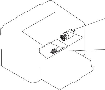
Plug/jack locations ........................................................................................................................ |
120 |
Figure 3-3 Engine controller PCA connectors ................................................................................................ |
121 |
|
Figure 3-4 |
External view ................................................................................................................................. |
122 |
Figure 3-5 Cross section view ........................................................................................................................ |
123 |
|
Figure 3-6 General timing diagram ................................................................................................................. |
125 |
|
Figure 3-7 |
Circuit diagram .............................................................................................................................. |
126 |
Figure 4-1 Base product (no optional trays or accessories) ........................................................................... |
163 |
|
Figure 4-2 |
Simplex model .............................................................................................................................. |
164 |
Figure 4-3 |
Duplex model ................................................................................................................................ |
166 |
Figure 4-4 Internal assemblies (1 of 3) ........................................................................................................... |
168 |
|
Figure 4-5 Internal assemblies (2 of 3) ........................................................................................................... |
170 |
|
Figure 4-6 Internal assemblies (3 of 3) ........................................................................................................... |
172 |
|
Figure 4-7 |
PCAs ............................................................................................................................................. |
174 |
xvi |
ENWW |

1 Theory of operation
●Basic operation
●Formatter-control system
●Engine-control system
●Image-formation system
●Pickup, feed, and delivery system
●Main-input tray or priority input slot
ENWW |
1 |

Basic operation
Major product systems
The product contains the following major systems:
●Engine-control system
●Laser/scanner system
●Image-formation system
●Pickup-and-feed system
Product block diagram
Figure 1-1 Product block diagram
LASER/SCANNER SYSTEM
ENGINE CONTROL |
IMAGE-FORMATION SYSTEM |
SYSTEM |
|
|
|
PICKUP-AND-FEED SYSTEM
2 Chapter 1 Theory of operation |
ENWW |
Sequence of operation
The DC controller in the engine-control system controls the operational sequences of the product. The table below describes durations and operations for each period of a print operation from when the product is turned on until the motor stops rotating.
Normal sequence of operation
Table 1-1 Sequence of operation
Name |
Timing |
Purpose |
|
|
|
WAIT |
From the time the power switch is turned on, the door |
Brings the product to ready state. The product |
|
is closed or the product exits Sleep mode until the |
performs the following during the operations: |
|
product gets ready for a print operation. |
● Detects the print cartridge |
|
|
|
|
|
● Heats the fuser film in the fuser |
|
|
● Rotates, and the stops, the main motor |
STBY (standby) From the end of the WAIT or LSTR period until either a print command is sent or the power switch is turned off.
Maintains the product in printable condition. The product performs the following during the operation:
●Enters Auto-Off mode if Auto-Off command is received
INTR (initial |
From the time a print command is received until the |
rotation) |
paper is picked up. |
The product performs the following during the operations:
●Drives the main motor
●Activates the high-voltage power supply
●Activates the laser/scanner
●Warms the fuser heater
From the end of the INTR period until the last sheet |
|
|
completes the fuser operation. |
Forms the image on the photosensitive drum based on the VIDEO signals from the formatter. Transfers and fuses the toner image to the paper.
LSTR (last |
From the end of the PRINT period until the main motor |
rotation) |
stops rotating. |
Moves the last printed sheet out of the product. The product performs the following during the operations:
●Stops the main motor
●Deactivates the high-voltage power supply
●Deactivates the laser/scanner
●Deactivates the fuser heater
The product enters the INTR period as the LSTR period is completed, if the formatter sends another print command.
ENWW |
Basic operation 3 |

Formatter-control system
The formatter is responsible for the following procedures:
●Controlling sleep mode
●Receiving and processing print data from the various product interfaces
●Monitoring control-panel functions and relaying product-status information (through the control panel and the network or bidirectional interface)
●Developing and coordinating data placement and timing with the DC controller PCA
●Storing font information
●Communicating with the host computer through the network or the bidirectional interface
The formatter receives a print job from the network or bidirectional interface and separates it into image information and instructions that control the printing process. The DC controller PCA synchronizes the image-formation system with the paper-input and -output systems, and then signals the formatter to send the print-image data.
Sleep mode
 NOTE: This product uses an Auto-Off feature for sleep mode.
After a user-specified time, the Auto-Off feature automatically conserves electricity by substantially reducing power consumption when the product is not printing. After a user-specified time, the product automatically reduces its power consumption (Auto-Off). The product returns to the ready state when a button is pressed, a print job is received, or a door is opened. When the product is in Auto-Off mode, all of the control-panel LEDs and the power button backlight LED are off.
 NOTE: Although the product lights are off in Auto-Off mode, the product functions normally when it receives a print job.
Input/output
The product receives print data primarily from the following:
●Hi-Speed USB 2.0 port
●802.11b/g wireless networking (wireless models only)
CPU
The formatter incorporates a 400 MHz Helium processor.
Memory
The random access memory (RAM) on the formatter PCA contains the page, I/O buffers, and the font storage area. RAM stores printing and font information received from the host system, and can also serve to temporarily store a full page of print-image data before the data is sent to the print engine.
4 Chapter 1 Theory of operation |
ENWW |

Firmware
●HP LaserJet Professional P1560 Printer series
◦The product has 8 MB of Synchronous DRAM, which is used for run-time firmware imaging and specific print job information for the print job.
●HP LaserJet Professional P1600 Printer series
◦The product has 32 MB of Synchronous DRAM, which is used for run-time firmware imaging and specific print job information for the print job.
Memory use
●HP LaserJet Professional P1560 Printer series
◦The product has a 2 KB EEPROM and 64 MB of NAND Flash Memory, which is used for product configuration information and printer driver firmware.
●HP LaserJet Professional P1600 Printer series
◦The product has a 8 KB EEPROM and 64 MB of NAND Flash Memory, which is used for product configuration information and printer driver firmware.
PJL overview
The printer job language (PJL) is an integral part of configuration, in addition to the standard printer command language (PCL). With standard cabling, the product can use PJL to perform a variety of functions such as these:
●Two-way communication with the host computer through a network connection or a USB connection. The product can inform the host about such things as the control-panel settings, and the control-panel settings can be changed from the host.
●Dynamic I/O switching. The product uses this switching to be configured with a host on each I/O. The product can receive data from more than one I/O simultaneously, until the I/O buffer is full. This can occur even when the product is offline.
●Context-sensitive switching. The product can automatically recognize the personality (PS or PCL) of each job and configure itself to serve that personality.
●Isolation of print environment settings from one print job to the next. For example, if a print job is sent to the product in landscape mode, the subsequent print jobs print in landscape mode only if they are formatted for landscape printing.
LEDM overview
 NOTE: HP LaserJet Professional P1600 Printer series
The low-end data model (LEDM) provides one consistent data representation method and defines the dynamic and capabilities tickets shared between clients and devices, as well as the access protocol, event, security, and discovery methods.
ACL overview
The advanced control language (ACL) is a language that supports product control and firmware downloads in printers that support both PJL/PCL and host-based printing. Each sequence of ACL
ENWW |
Formatter-control system 5 |
commands must be preceded by a unified exit command (UEL) and an @PJL ENTER LANGUAGE=ACL command. The ACL sequence is always followed by a UEL. Any number of commands can be placed between the UELs. The only exception to these rules is the download command. If a firmware download is done, the download command must be the last command in the sequence. It will not be followed by a UEL.
The firmware searches for the UEL sequence when parsing commands. However, while downloading binary data such as host-based code or NVRAM data the firmware suspends UEL parsing. To handle hosts that “disappear” during binary sequences, the firmware times out all ACL command sessions. If a timeout occurs during a non-download command sequence, it is treated as the receipt of a UEL. If a timeout occurs during firmware download the product resets.
Control panel
The formatter sends and receives product status and command data to and from the control-panel PCA.
6 Chapter 1 Theory of operation |
ENWW |
Engine-control system
The engine-control system coordinates all product functions, according to commands that the formatter sends. The engine-control system drives the laser/scanner system, the image-formation system, and the pickup/feed/delivery system.
The engine control system contains the following major components:
●Engine-control unit (ECU)
◦DC controller
◦Low-voltage power supply
●High-voltage power supply
●Fuser control
Figure 1-2 Engine-control system
ENGINE CONTROL SYSTEM
DC controller
Low-voltage power supply
LASER/SCANNER SYSTEM
Formatter |
IMAGE-FORMATION SYSTEM |
High-voltage power supply
MEDIA-FEED SYSTEM
Fuser control
ENWW |
Engine-control system 7 |
Motors, fans, clutches, solenoids, switches, and sensors
Figure 1-3 Motors
M1
M2
Table 1-2 Motors
Item |
Description |
Components driven |
|
|
|
|
|
M1 |
Main motor |
● |
Pickup roller |
|
|
● |
Feed roller |
|
|
● |
Photosensitive drum |
|
|
● |
Developing roller |
|
|
● |
Pressure roller |
|
|
● |
Delivery roller |
|
|
● |
Duplex feed roller |
|
|
|
|
M2 |
Scanner motor |
● |
Scanner mirror |
|
|
|
|
8 Chapter 1 Theory of operation |
ENWW |

Figure 1-4 Fans
FM1
Table 1-3 Fans
Item |
Description |
|
|
FM1 |
Main fan |
|
|
ENWW |
Engine-control system 9 |
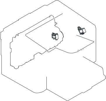
Figure 1-5 Solenoids and clutches
SL2
SL1
Table 1-4 Solenoids and clutches
Item |
Description |
|
|
SL1 |
Pickup solenoid |
|
|
SL2 |
Duplex reverse solenoid |
|
NOTE: Duplex models only. |
|
|
10 Chapter 1 Theory of operation |
ENWW |

Figure 1-6 Switches
Table 1-5 Switches |
|
Item |
Description |
SW501 |
Cartridge-door switch |
SW502 |
Power switch; not shown |
Figure 1-7 |
Sensors |
|
PS702 |
|
PS701 |
|
PS751 |
Table 1-6 Sensors |
|
Item |
Description |
PS701 |
Fuser delivery sensor |
ENWW |
Engine-control system 11 |
Table 1-6 Sensors (continued)
Item |
Description |
|
|
PS702 |
Media-width sensor |
|
|
PS751 |
Top-of-Page (TOP) sensor |
|
|
PS901 |
Main-motor rotation-number sensor; not shown |
|
|
12 Chapter 1 Theory of operation |
ENWW |
Loading...