


LASERJET PRO 200 COLOR
Troubleshooting Manual
M251n |
M251nw |

HP LaserJet Pro 200 color M251 Series Printer
Troubleshooting Manual
Copyright and License
© 2012 Copyright Hewlett-Packard
Development Company, L.P.
Reproduction, adaptation, or translation without prior written permission is prohibited, except as allowed under the copyright laws.
The information contained herein is subject to change without notice.
The only warranties for HP products and services are set forth in the express warranty statements accompanying such products and services. Nothing herein should be construed as constituting an additional warranty. HP shall not be liable for technical or editorial errors or omissions contained herein.
Part number: CF146-90968
Edition 1, 9/2012
Trademark Credits
Microsoft®, Windows®, Windows® XP, and Windows Vista® are U.S. registered trademarks of Microsoft Corporation.
ENERGY STAR and the ENERGY STAR mark are registered U.S. marks.

Conventions used in this guide

 TIP: Tips provide helpful hints or shortcuts.
 NOTE: Notes provide important information to explain a concept or to complete a task.
CAUTION: Cautions indicate procedures that you should follow to avoid losing data or damaging the product.
WARNING! Warnings alert you to specific procedures that you should follow to avoid personal injury, catastrophic loss of data, or extensive damage to the product.
ENWW |
iii |

Table of contents
1 Theory of operation .......................................................................................................... |
1 |
Basic operation ........................................................................................................................ |
2 |
Major product systems ............................................................................................... |
2 |
Product components .................................................................................................. |
3 |
Sequence of operation ............................................................................................... |
4 |
Engine control system ............................................................................................................... |
5 |
DC controller ............................................................................................................ |
6 |
Low-voltage power supply .......................................................................................... |
7 |
High-voltage power supply ......................................................................................... |
8 |
Laser/scanner system ............................................................................................................... |
9 |
Laser failure detection ................................................................................................ |
9 |
Image-formation system ........................................................................................................... |
10 |
Image-formation process .......................................................................................... |
10 |
Latent-image formation stage .................................................................................... |
11 |
Step 1: primary charging .......................................................................... |
12 |
Step 2: laser-beam exposure ..................................................................... |
12 |
Developing stage .................................................................................................... |
12 |
Step 3: development ................................................................................. |
13 |
Transfer stage ......................................................................................................... |
14 |
Step 4: primary transfer ............................................................................ |
14 |
Step 5: secondary transfer ......................................................................... |
14 |
Step 6: separation from the ITB .................................................................. |
15 |
Fusing stage ........................................................................................................... |
15 |
Step 7: fusing .......................................................................................... |
15 |
ITB cleaning stage ................................................................................................... |
16 |
Step 8: ITB cleaning ................................................................................. |
16 |
Drum cleaning stage ................................................................................................ |
17 |
Step 9: drum cleaning .............................................................................. |
17 |
Pickup-and-feed system ........................................................................................................... |
18 |
Jam detection ......................................................................................................... |
19 |
USB flash drive ...................................................................................................................... |
20 |
ENWW |
v |
2 Solve problems ............................................................................................................... |
21 |
Solve problems checklist ......................................................................................................... |
22 |
Menu map ............................................................................................................................ |
24 |
Print a menu map (LCD control panel) ........................................................................ |
24 |
Print a menu map (touchscreen control panel) ............................................................. |
24 |
Troubleshooting process .......................................................................................................... |
25 |
Pre-troubleshooting checklist ..................................................................................... |
25 |
Power-on checks ..................................................................................................... |
27 |
Tools for troubleshooting ......................................................................................................... |
28 |
Component diagnostics ............................................................................................ |
28 |
LED diagnostics ........................................................................................ |
28 |
Network LEDs ........................................................................... |
28 |
Control panel LEDs .................................................................... |
29 |
Control-panel diagnostics .......................................................................... |
30 |
Engine diagnostics ................................................................................... |
30 |
Engine test ................................................................................ |
30 |
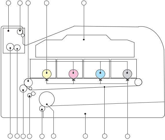
Diagrams ............................................................................................................... |
31 |
Plug/jack locations ................................................................................... |
31 |
DC controller PCA .................................................................................... |
32 |
Locations of major components .................................................................. |
34 |
General timing chart ................................................................................. |
36 |
General circuit diagram ............................................................................ |
37 |
Internal print-quality test pages .................................................................................. |
38 |
Interpret the Print Quality Page ................................................................... |
38 |
Print a cleaning page ............................................................................... |
38 |
Print a cleaning page (LCD control panel) .................................... |
39 |
Print a cleaning page (touchscreen control panel) .......................... |
39 |
Configuration page .................................................................................. |
39 |
Print a configuration page (LCD control panel) .............................. |
39 |
Print a configuration page (touchscreen control panel) ................... |
40 |
Print-quality troubleshooting tools .............................................................................. |
41 |
Repetitive image defects ............................................................................ |
41 |
Calibrate the product to align the colors ...................................................... |
41 |
Control-panel menus ................................................................................................ |
42 |
Setup Menu ............................................................................................. |
42 |
HP Web Services ...................................................................... |
42 |
Reports menu ............................................................................ |
43 |
Self Diagnostics menu ................................................................ |
44 |
System Setup menu .................................................................... |
45 |
Service menu ............................................................................ |
48 |
Network Setup menu ................................................................. |
50 |
vi |
ENWW |
Quick Forms menu .................................................................... |
51 |
Function specific menus ............................................................................. |
52 |
Apps ....................................................................................... |
52 |
USB Flash Drive ........................................................................ |
52 |
Interpret control panel messages ............................................................................... |
53 |
Control panel message types ..................................................................... |
53 |
Control panel messages ............................................................................ |
53 |
10.X00Y Supply Error ................................................................ |
53 |
49 Error, Turn off then on ........................................................... |
54 |
50.x Fuser Error ........................................................................ |
54 |
51.XX Error .............................................................................. |
54 |
54.XX Error .............................................................................. |
54 |
55.X Error ................................................................................ |
55 |
57 Fan Error, Turn off then on ..................................................... |
55 |
59.X Error ................................................................................ |
55 |
79 Error Turn off then on ............................................................ |
56 |
Black Cartridge Low .................................................................. |
56 |
Black in wrong position .............................................................. |
56 |
Black Very Low ......................................................................... |
56 |
Cleaning .................................................................................. |
57 |
Cyan Cartridge Low .................................................................. |
57 |
Cyan in wrong position .............................................................. |
57 |
Cyan Very Low ......................................................................... |
57 |
Device error, press OK .............................................................. |
58 |
Door open ................................................................................ |
58 |
Genuine HP supply installed ....................................................... |
58 |
Incompatible <color> ................................................................. |
58 |
Incorrect supplies ...................................................................... |
58 |
Install <color> cartridge ............................................................. |
59 |
Invalid driver Press [OK] ............................................................ |
59 |
Jam in Tray 1, Clear jam and then press OK ................................ |
59 |
Load tray 1 Press [OK] for available media .................................. |
59 |
Load Tray 1 <TYPE> <SIZE>, Press OK to use available media ....... |
59 |
Load Tray 1, <PLAIN> <SIZE> / Cleaning mode, OK to start ......... |
59 |
Magenta Cartridge Low ............................................................. |
60 |
Magenta in wrong position ........................................................ |
60 |
Magenta Very Low .................................................................... |
60 |
Manual Duplex Load Tray 1, Press OK ........................................ |
60 |
Memory is low. Press OK. .......................................................... |
61 |
Misprint, Press OK ..................................................................... |
61 |
Print failure, press OK. If error repeats, turn off then on. ................. |
61 |
ENWW |
vii |
Rear door open ......................................................................... |
61 |
Remove shipping lock from <color> cartridge ............................... |
62 |
Remove shipping locks from cartridges ........................................ |
62 |
Replace <color> ....................................................................... |
62 |
Supplies low ............................................................................. |
62 |
Unexpected size in tray 1 Load <size> Press [OK] ........................ |
62 |
Unsupported <color> Press [OK] to continue .............................. |
0 |
Used <color> in use ............................................................... |
0 |
Used <color> installed, to accept press OK ............................... |
0 |
Used supplies in use ............................................................... |
0 |
Yellow Cartridge Low ............................................................. |
0 |
Yellow in wrong position ......................................................... |
0 |
Yellow Very Low .................................................................... |
0 |
Event-log messages ............................................................................................... |
0 |
Clear jams ......................................................................................................................... |
0 |
Jam locations ....................................................................................................... |
0 |
Clear jams in the paper input tray .......................................................................... |
0 |
Clear jams from the output bin ............................................................................... |
0 |
Clear jams from the rear door ................................................................................ |
0 |
Solve paper-handling problems ............................................................................................. |
0 |
The product picks up multiple sheets of paper .......................................................... |
0 |
The product does not pick up paper ....................................................................... |
0 |
Solve image quality problems ............................................................................................... |
0 |
Use the correct paper type setting in the printer driver .............................................. |
0 |
Change the paper type setting for Windows ............................................. |
0 |
Change the paper type setting for Mac .................................................... |
0 |
Adjust color settings in the printer driver .................................................................. |
0 |
Change the color theme for a print job .................................................... |
0 |
Change the color options ....................................................................... |
0 |
Use paper that meets HP specifications ................................................................... |
0 |
Print a cleaning page ........................................................................................... |
0 |
Print a cleaning page (LCD control panel) ................................................ |
0 |
Print a cleaning page (touchscreen control panel) ...................................... |
0 |
Calibrate the product to align the colors .................................................................. |
0 |
Check the toner cartridges ..................................................................................... |
0 |
Print the Supplies Status page ................................................................. |
0 |
Inspect the print cartridge for damage ..................................................... |
0 |
Repeating defects .................................................................................. |
0 |
Use the printer driver that best meets your printing needs .......................................... |
0 |
Solve performance problems ................................................................................................ |
0 |
Factors affecting print performance ........................................................................ |
0 |
viii |
ENWW |
Print speeds ............................................................................................. |
84 |
The product does not print or it prints slowly ............................................................... |
85 |
The product does not print ......................................................................... |
85 |
The product prints slowly ........................................................................... |
86 |
Solve product connectivity problems ......................................................................................... |
87 |
Solve direct-connect problems ................................................................................... |
87 |
Solve network problems ........................................................................................... |
87 |
Poor physical connection ........................................................................... |
87 |
The computer is using the incorrect IP address for the product ........................ |
87 |
The computer is unable to communicate with the product .............................. |
88 |
The product is using incorrect link and duplex settings for the network ............ |
88 |
New software programs might be causing compatibility problems .................. |
88 |
The computer or workstation might be set up incorrectly ................................ |
88 |
The product is disabled, or other network settings are incorrect ...................... |
88 |
Solve wireless network problems ............................................................................... |
89 |
Wireless connectivity checklist ................................................................... |
89 |
The control panel displays the message: The wireless feature on this product |
|
has been turned off .................................................................................. |
90 |
The product does not print after the wireless configuration completes .............. |
90 |
The product does not print, and the computer has a third-party firewall |
|
installed .................................................................................................. |
90 |
The wireless connection does not work after moving the wireless router or |
|
product ................................................................................................... |
90 |
Cannot connect more computers to the wireless product ................................ |
91 |
The wireless product loses communication when connected to a VPN ............. |
91 |
The network does not appear in the wireless networks list ............................. |
91 |
The wireless network is not functioning ........................................................ |
92 |
Service mode functions ........................................................................................................... |
93 |
Service menu .......................................................................................................... |
93 |
Service menu settings ................................................................................ |
93 |
Restore the factory-set defaults ................................................................... |
93 |
Restore the factory-set defaults (LCD control panel) ......................... |
94 |
Restore the factory-set defaults (touchscreen control panel) .............. |
94 |
Secondary service menu .......................................................................................... |
94 |
Open the secondary service menu (LCD control panel) .................................. |
94 |
Open the secondary service menu (touchscreen control panel) ....................... |
94 |
Secondary service menu structure ............................................................... |
95 |
Engine resets .......................................................................................................... |
96 |
Engine test page ...................................................................................... |
96 |
Cold reset ............................................................................................... |
96 |
NVRAM initialization ................................................................................ |
96 |
ENWW |
ix |
Product updates ..................................................................................................................... |
97 |
Appendix A Service and support ....................................................................................... |
99 |
Hewlett-Packard limited warranty statement ............................................................................. |
100 |
HP's Premium Protection Warranty: LaserJet print cartridge limited warranty statement .................. |
102 |
Data stored on the print cartridge ........................................................................................... |
103 |
End User License Agreement .................................................................................................. |
104 |
OpenSSL ............................................................................................................................. |
106 |
Customer support ................................................................................................................. |
107 |
Repack the product .............................................................................................................. |
108 |
Appendix B Product specifications ................................................................................... |
109 |
Physical specifications .......................................................................................................... |
110 |
Power consumption, electrical specifications, and acoustic emissions .......................................... |
110 |
Environmental specifications .................................................................................................. |
110 |
Appendix C Regulatory information ................................................................................. |
111 |
FCC regulations ................................................................................................................... |
112 |
Environmental product stewardship program ........................................................................... |
113 |
Protecting the environment ...................................................................................... |
113 |
Ozone production ................................................................................................. |
113 |
Power consumption ............................................................................................... |
113 |
Paper use ............................................................................................................. |
113 |
Plastics ................................................................................................................. |
113 |
HP LaserJet print supplies ....................................................................................... |
113 |
Return and recycling instructions ............................................................................. |
114 |
United States and Puerto Rico .................................................................. |
114 |
Multiple returns (more than one cartridge) .................................. |
114 |
Single returns .......................................................................... |
114 |
Shipping ................................................................................ |
114 |
Non-U.S. returns .................................................................................... |
115 |
Paper .................................................................................................................. |
115 |
Material restrictions ............................................................................................... |
115 |
Disposal of waste equipment by users in private households in the European Union ...... |
115 |
Chemical substances ............................................................................................. |
115 |
Material Safety Data Sheet (MSDS) ......................................................................... |
116 |
For more information ............................................................................................. |
117 |
Declaration of conformity ...................................................................................................... |
118 |
Declaration of conformity (wireless model) .............................................................................. |
120 |
Certificate of Volatility .......................................................................................................... |
122 |
x |
ENWW |
Safety statements ................................................................................................................. |
123 |
Laser safety .......................................................................................................... |
123 |
Canadian DOC regulations .................................................................................... |
123 |
VCCI statement (Japan) .......................................................................................... |
123 |
Power cord instructions .......................................................................................... |
123 |
Power cord statement (Japan) ................................................................................. |
123 |
EMC statement (Korea) .......................................................................................... |
124 |
Laser statement for Finland ..................................................................................... |
125 |
GS statement (Germany) ........................................................................................ |
125 |
Substances Table (China) ....................................................................................... |
126 |
Restriction on Hazardous Substances statement (Turkey) ............................................. |
126 |
Additional statements for wireless products .............................................................................. |
127 |
FCC compliance statement—United States ................................................................ |
127 |
Australia statement ................................................................................................ |
127 |
Brazil ANATEL statement ........................................................................................ |
127 |
Canadian statements ............................................................................................. |
127 |
European Union regulatory notice ........................................................................... |
127 |
Notice for use in France ......................................................................................... |
128 |
Notice for use in Russia ......................................................................................... |
128 |
Korean statement .................................................................................................. |
128 |
Taiwan statement .................................................................................................. |
129 |
Index ............................................................................................................................... |
131 |
ENWW |
xi |

List of tables
Table 1-1 Sequence of operation ............................................................................................................ |
4 |
Table 2-1 DC controller connectors ....................................................................................................... |
32 |
Table 2-2 Major components ............................................................................................................... |
34 |
Table 2-3 Repetitive image defects ........................................................................................................ |
41 |
Table 2-4 Event-log messages ............................................................................................................... |
64 |
Table 2-5 Secondary Service menu ....................................................................................................... |
95 |
Table B-1 Physical specifications ......................................................................................................... |
110 |
Table B-2 Environmental specifications ................................................................................................ |
110 |
ENWW |
xiii |

List of figures
Figure 1-1 Product systems ..................................................................................................................... |
2 |
Figure 1-2 Product components ............................................................................................................... |
3 |
Figure 1-3 Engine control system components ........................................................................................... |
5 |
Figure 1-4 DC controller circuit diagram .................................................................................................. |
6 |
Figure 1-5 Low-voltage power supply ...................................................................................................... |
7 |
Figure 1-6 High-voltage power supply ..................................................................................................... |
8 |
Figure 1-7 Laser/scanner system ............................................................................................................. |
9 |
Figure 1-8 Image-formation system ........................................................................................................ |
10 |
Figure 1-9 Image-formation process ...................................................................................................... |
11 |
Figure 1-10 Primary charging ............................................................................................................... |
12 |
Figure 1-11 Laser-beam exposure ......................................................................................................... |
12 |
Figure 1-12 Development ..................................................................................................................... |
13 |
Figure 1-13 Primary transfer ................................................................................................................. |
14 |
Figure 1-14 Secondary transfer ............................................................................................................ |
14 |
Figure 1-15 Separation from the ITB ...................................................................................................... |
15 |
Figure 1-16 Fusing .............................................................................................................................. |
15 |
Figure 1-17 ITB cleaning ...................................................................................................................... |
16 |
Figure 1-18 Drum cleaning .................................................................................................................. |
17 |
Figure 1-19 Pickup-and-feed system ....................................................................................................... |
18 |
Figure 2-1 DC controller connectors ...................................................................................................... |
32 |
Figure 2-2 Major components .............................................................................................................. |
34 |
Figure 2-3 Timing diagram ................................................................................................................... |
36 |
Figure 2-4 Circuit diagram ................................................................................................................... |
37 |
ENWW |
xv |

1 Theory of operation
This chapter presents an overview of the major components of the printer and includes a detailed discussion of the image-formation system.
●Basic operation
●Engine control system
●Laser/scanner system
●Image-formation system
●Pickup-and-feed system
●USB flash drive
ENWW |
1 |

Basic operation
Major product systems
The product includes the following systems:
●Engine control system
●Laser/scanner system
●Image-formation system
●Pickup-and-feed system
Figure 1-1 Product systems
ENGINE CONTROL
SYSTEM
LASER/SCANNER SYSTEM
IMAGE-FORMATION SYSTEM
PICKUP-AND-FEED SYSTEM
2 |
Chapter 1 Theory of operation |
ENWW |
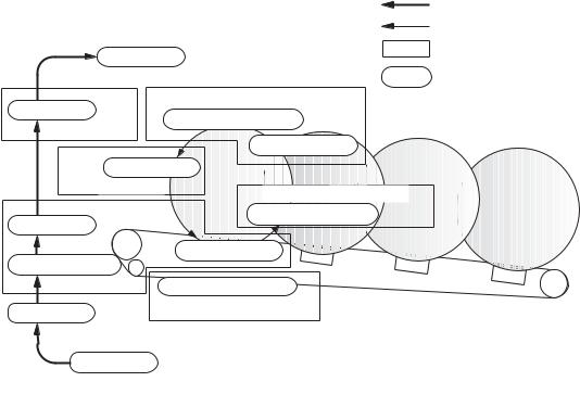
Product components |
|
|
||
Figure 1-2 |
Product components |
|
||
1 |
2 |
3 |
4 |
5 |
14 |
13 |
12 |
11 |
10 |
9 |
8 |
7 |
6 |
|
|
|
|
|
|
|
|
|
Item |
|
|
Description |
|
Item |
|
Description |
|
|
|
|
|
|
|
|
|
|
1 |
|
|
Fuser unit |
|
|
8 |
|
Cassette |
|
|
|
|
|
|
|
|
|
2 |
|
|
Delivery roller |
|
9 |
|
Pickup roller |
|
|
|
|
|
|
|
|
|
|
3 |
|
|
ITB drive roller |
|
10 |
|
Separation roller |
|
|
|
|
|
|
|
|
||
4 |
|
|
Photosensitive drum |
11 |
|
Registration roller |
||
|
|
|
|
|
|
|
||
5 |
|
|
Laser scanner assembly |
12 |
|
Secondary transfer roller |
||
|
|
|
|
|
|
|
|
|
6 |
|
|
Transfer pad |
|
13 |
|
Fusing film |
|
|
|
|
|
|
|
|
||
7 |
|
|
Intermediate transfer belt (ITB) |
14 |
|
Pressure roller |
||
|
|
|
|
|
|
|
|
|
ENWW |
Basic operation |
3 |

Sequence of operation
Table 1-1 Sequence of operation
Period |
Duration |
Purpose |
Remarks |
|
|
|
|
WAIT |
From the time the power is |
Clears the potential from the |
Detects the cartridge |
|
turned on or the door is |
drum surface, adjusts the |
presence and environment; |
|
closed, until the printer is |
drum phase, and cleans the |
completes any required |
|
ready for a print operation |
ITB |
calibration (color registration |
|
|
|
control and image stability) |
|
|
|
|
STBY (Standby period) |
From end of the WAIT or |
Maintains the printer in |
The printer enters sleep mode |
|
LSTR period until either the |
readiness for a print |
when the formatter sends a |
|
print command is received |
command |
sleep command, and |
|
from the formatter or the |
|
performs color registration |
|
power is turned off |
|
and the image stability |
|
|
|
control when the formatter |
|
|
|
sends those commands |
|
|
|
|
INTR (Initial rotation) |
From the time the print |
Prepares the photosensitive |
|
|
command is received until the |
drum for printing |
|
|
media is picked up |
|
|
|
|
|
|
From the end of INTR period |
Forms the images on the |
Performs image stabilization |
|
|
until the fuser paper sensor |
photosensitive drum and |
at a specified print interval or |
|
detects the trailing edge of |
transfers the toner image to |
at specified times |
|
paper |
the print media |
|
|
|
|
|
LSTR (Last rotation) |
From the end of the PRINT |
Moves the printed sheet out |
The printer enters the INTR |
|
period until the delivery motor |
of the printer |
period as soon as the |
|
stops rotating |
|
formatter sends another print |
|
|
|
command |
|
|
|
|
4 |
Chapter 1 Theory of operation |
ENWW |
Engine control system
The engine control system coordinates all printer functions and drives the other three systems.
The engine control system contains the DC controller, high-voltage power-supply PCA, low-voltage power-supply unit, and fuser control.
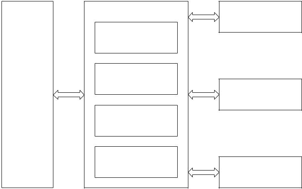
Figure 1-3 Engine control system components
Engine-control system
Laser scanner system
DC controller
Low-voltage power supply
Formatter |
Image-formation system |
High-voltage power supply
Fuser control
Pickup, feed and delivery system
ENWW |
Engine control system |
5 |
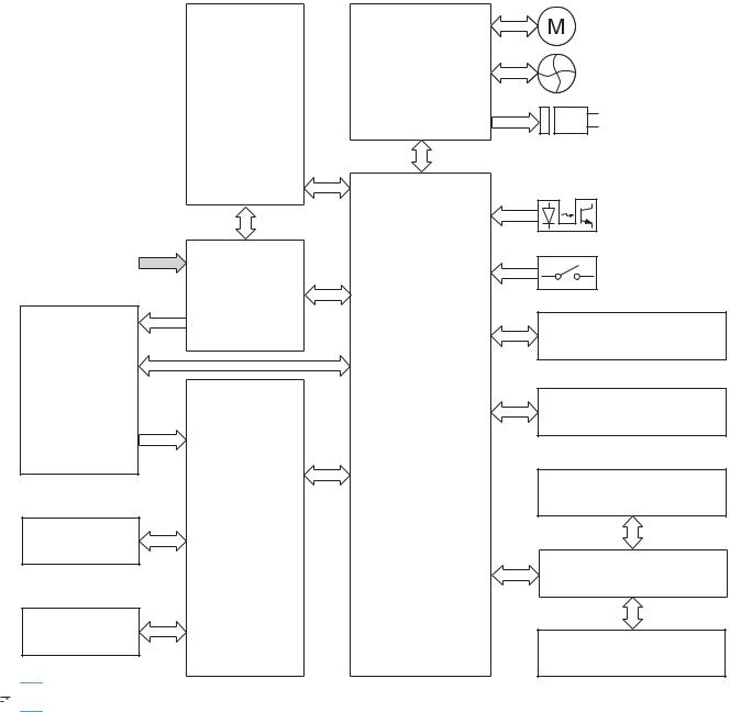
DC controller
Figure 1-4 DC controller circuit diagram
Driver
Low-voltage power supply
AC input
Fuser power supply
Fuser
DC controller
High-voltage
power supply
T2 roller
Cartridge
 NOTE: USB block for touchscreen-equipped models only.
Motor
Fan
Solenoid
Photointerrupter
Switch
ITB assembly
Laser scanner assembly
USB (NOTE)
Formatter
Control panel
6 |
Chapter 1 Theory of operation |
ENWW |
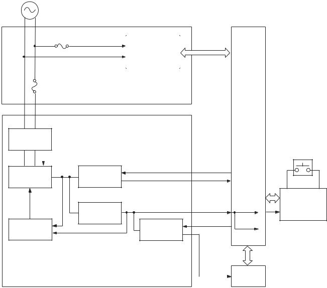
Low-voltage power supply
Figure 1-5 Low-voltage power supply
AC input
DC controller
Fuse
FU901
Fuser control circuit
Fuse
FU801
Fuser power supply
Rectifying
circuit
PWSV |
Power switch |
|
SW801 |
||
|
||
|
|
+24V |
+24VR |
+24V |
REM24V |
|
+24VA |
|
|||
generation |
|
control circuit |
|
|
circuit |
|
|
|
|
|
|
+3.3V |
+3.3VA |
+3.3VA |
|
|
generation |
||
|
|
|
|
|
|
|
circuit |
VCTRLOFF |
+3.3VB |
Protection |
|
+3.3V |
||
|
|
|||
circuit |
|
control circuit |
|
|
+24VA Power switch
control circuit
Low-voltage power supply |
+3.3VC |
Formatter |
|
||
|
|
ENWW |
Engine control system |
7 |
High-voltage power supply
Figure 1-6 High-voltage power supply
Primary charging bias circuit |
|
|
|
Developing bias circuit |
||
|
|
|
|
|
|
|
|
|
|
|
|
|
|
|
|
|
|
|
|
|
Cartridge
Photosensitive drum
T1 pad
ITB cleaning |
ITB |
|
|
ass’y |
|
|
T2 roller |
|
|
|
|
|
|
|
|
|
|
|
|
|
|
|
|
|
|
|
|
|
|
|
|
|
|
|
|
|
|
|
|
|
|
|
|
|
|
|
|
|
|
|
|
|
|
|
ITB cleaning brush |
|
ITB cleaning roller |
|
T2 bias circui |
|
T1 bias circuit |
|
|||||
|
|
bias circuit |
|
bias circuit |
|
|
|
|||||||
|
|
|
|
|
|
|
|
|
||||||
|
|
|
|
|
|
|
|
|
|
|
|
|
|
|
|
|
|
|
|
|
|
|
|
|
|
|
|
High-voltage power supply |
|
DC controller
8 |
Chapter 1 Theory of operation |
ENWW |
Laser/scanner system
The formatter sends video signals to the DC controller, which controls the laser/scanner. When the laser/scanner system receives those signals, it converts them to latent images on the photosensitive drum.
Figure 1-7 Laser/scanner system
Laser assembly
Scanner mirror
Scanner motor assembly
BD sensor
Photosensitive drum
(Y)
Photosensitive drum
(M)
Photosensitive drum
(C)
Photosensitive drum
(K)
DC controller
Laser failure detection
The optical unit failure detection sensor manages the laser/scanner unit failure-detection functions. The DC controller identifies the laser/scanner unit failure and notifies the formatter if the laser/scanner unit encounters the following conditions:
●Scanner motor failure
●BD failure
ENWW |
Laser/scanner system |
9 |

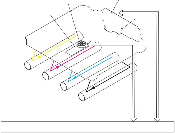
Image-formation system
The image-formation system forms a toner image on media. The product includes four toner cartridges that contain the toner. Toner is applied in the following order, using only the colors necessary for a specific image: yellow (Y), magenta (M), cyan (C), and black (K).
Figure 1-8 Image-formation system
DC controller
High-voltage power supply
Fuser
Laser scanner assembly
Cartridge
Y |
M |
C |
K |
ITB
T1 pad |
Photosensitive drum |
T2 roller |
|
Image-formation process
Laser printing requires the interaction of several different technologies including electronics, optics, and electrographics to provide a printed page. Each process functions independently and must be coordinated with the other processes. Image formation consists of the following processes:
●Latent-image formation
●Development
●Transfer
10 Chapter 1 Theory of operation |
ENWW |
●Fuser
●ITB cleaning
●Drum cleaning
These processes are divided into nine steps, which are shown in Figure 1-9 Image-formation process on page 11 and described in the following sections.
Figure 1-9 |
Image-formation process |
|
|
|
|
|
: Media path |
|
|
|
: Direction of drum rotation |
|
Delivery |
|
: Block |
|
|
|
|
|
|
|
: Step |
|
|
Latent image formation |
|
7. Fusing |
|
2. Laser beam exposure |
|
Fuser |
|
|
|
|
1. Primary charging |
|
|
|
|
|
|
|
3. Development |
|
|
|
Development |
Photosensitive drum cleaning |
|
|
|
|
|
|
Transfer |
9. Drum cleaning |
|
6. Separation |
|
||
|
|
||
|
|
4. Primary transfer |
|
5. Secondary transfer |
|
|
|
|
|
8. ITB cleaning |
|
Registration |
|
ITB cleaning |
|
Pickup
Latent-image formation stage
During the two steps that comprise this stage, a latent image is formed by applying a negative charge to the photosensitive drum. You cannot see this image on the drum.
ENWW |
Image-formation system 11 |
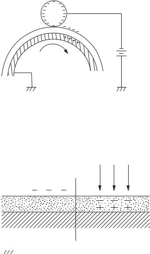
Step 1: primary charging
A high-voltage DC bias is applied to the primary charging roller, which is made of conductive rubber and is in contact with the drum surface. As the roller moves across the drum, it applies the negative charge to that surface.
Figure 1-10 Primary charging
Primary charging roller
DC bias
Photosensitive drum
Step 2: laser-beam exposure
The laser beam scans the photosensitive drum to neutralize the negative charge on portions of the drum surface. An electrostatic latent image is formed where the negative charge was neutralized.
Figure 1-11 Laser-beam exposure
Laser beam
|
|
|
|
|
|
|
|
|
|
|
|
|
|
|
|
|
|
|
|
|
|
|
|
|
|
|
|
|
|
|
|
|
|
|
|
|
|
|
|
|
|
|
|
|
|
|
|
|
|
|
|
|
|
|
|
|
|
|
|
Unexposed area |
Exposed area |
||||||||||||||
|
|
|
|
|
|
|
|
|
|
|
|
|
|
|
|
|
|
|
Developing stage
The developer roller comes in contact with the photosensitive drum and deposits toner on the electrostatic latent image.
12 Chapter 1 Theory of operation |
ENWW |
Step 3: development
Toner acquires a negative charge as a result of the friction from the developer roller rotating against the developer blade. When the negatively charged toner comes in contact with the drum, it adheres to the electrostatic latent image. When the toner is on the drum, the image becomes visible.
Figure 1-12 Development
Developer blade
|
Developer roller |
|
DC negative bias |
Exposed area |
Unexposed area |
Unexposed area |
Exposed area |
Photosensitive drum
ENWW |
Image-formation system 13 |
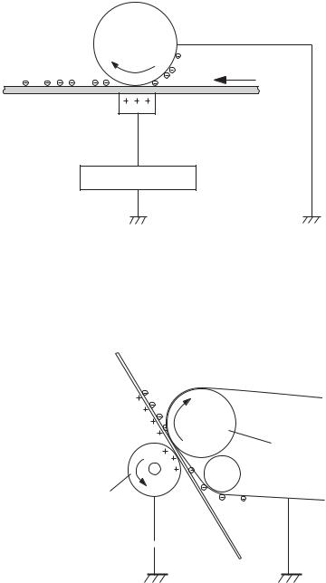
Transfer stage
Step 4: primary transfer
The toner image on the photosensitive drum is transferred to the ITB. The DC positive bias is applied to the primary transfer pad. The negatively charged toner transfers to the ITB from the drum surface.
Figure 1-13 Primary transfer
Photosensitive
drum
ITB
T1 pad
T1 bias
Step 5: secondary transfer
The toner image on the ITB is transferred to the print media. The DC positive bias is applied to the secondary transfer roller. As the media passes between the secondary transfer roller and the ITB, the toner image is transferred to the media.
Figure 1-14 Secondary transfer
Media
ITB
ITB drive roller
Secondary transfer roller
DC bias 
14 Chapter 1 Theory of operation |
ENWW |
Step 6: separation from the ITB
The elasticity of the print media and the curvature of the ITB drive roller cause the media to separate from the ITB.
Figure 1-15 Separation from the ITB
Media
ITB
ITB drive roller
Secondary transfer roller
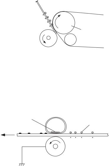
Fusing stage
Until the fusing stage is complete, the image is not permanently affixed to the print media. The toner can be easily smudged until the heat and pressure of the fusing process fix the image to the sheet.
Step 7: fusing
The product uses an on-demand fixing method to fix the toner image onto the media. The toner image is permanently affixed to the print media by heat and pressure.
Figure 1-16 Fusing
Fuser film
Fuser heater
Toner
Paper
Pressure roller
ENWW |
Image-formation system 15 |
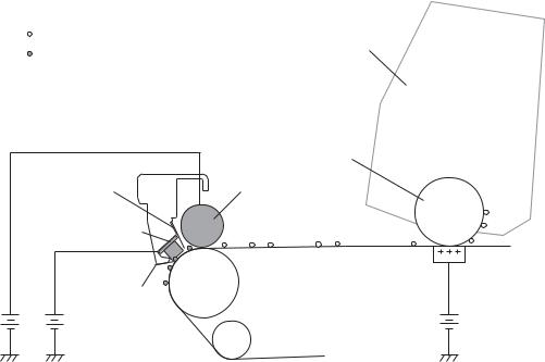
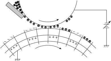
ITB cleaning stage
Step 8: ITB cleaning
The ITB cleaning roller and the cleaning brush are applied with the DC positive bias to charge the residual toner positive. Because the primary transfer pad is also applied with the DC positive bias, the positively charged residual toner is reverse-transferred to the photosensitive drum from the ITB surface.
Figure 1-17 ITB cleaning
Positive potential waste toner
Cartridge
Negative potential waste toner
Partition sheet |
ITB cleaning brush |
Sweeper strip |
Photosensitive drum ITB cleaning roller
IT B
DC bias |
DC bias |
16 Chapter 1 Theory of operation |
ENWW |
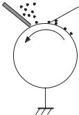
Drum cleaning stage
Not all of the toner is removed from the photosensitive drum during the transfer stage. During the cleaning stage, the residual, or waste, toner is cleared from the drum surface to prepare the surface for the next latent-image formation.
Step 9: drum cleaning
The cleaning blade scrapes the residual toner off the surface of the photosensitive drum and deposits it in the waste-toner container. The drum is now clear and is ready for the next image-formation process.
Figure 1-18 Drum cleaning
Cleaning blade |
Blowout seal |
Photosensitive
drum
ENWW |
Image-formation system 17 |
 Loading...