


 Loading...
LASERJET PRO 100 COLOR MFP M175
Service Manual

HP LaserJet Pro 100 color MFP M175
Service Manual
Copyright and License
© 2011 Copyright Hewlett-Packard
Development Company, L.P.
Reproduction, adaptation, or translation without prior written permission is prohibited, except as allowed under the copyright laws.
The information contained herein is subject to change without notice.
The only warranties for HP products and services are set forth in the express warranty statements accompanying such products and services. Nothing herein should be construed as constituting an additional warranty. HP shall not be liable for technical or editorial errors or omissions contained herein.
Part number: CE865-90968
Edition 1, 4/2011
Trademark Credits
Microsoft®, Windows®, Windows® XP, and Windows Vista® are U.S. registered trademarks of Microsoft Corporation.

Conventions used in this guide

 TIP: Tips provide helpful hints or shortcuts.
 NOTE: Notes provide important information to explain a concept or to complete a task.
CAUTION: Cautions indicate procedures that you should follow to avoid losing data or damaging the product.
WARNING! Warnings alert you to specific procedures that you should follow to avoid personal injury, catastrophic loss of data, or extensive damage to the product.
ENWW |
iii |

Table of contents
1 Removal and replacement ................................................................................................ |
1 |
Introduction ............................................................................................................................. |
2 |
Removal and replacement strategy ............................................................................................. |
2 |
Electrostatic discharge .............................................................................................................. |
3 |
Required tools .......................................................................................................................... |
3 |
Service approach ..................................................................................................................... |
4 |
Before performing service .......................................................................................... |
4 |
After performing service ............................................................................................. |
4 |
Post-service test ......................................................................................................... |
4 |
Product verification test ............................................................................... |
4 |
Parts removal order ................................................................................................... |
5 |
Removal and replacement procedures ........................................................................................ |
7 |
Print cartridges .......................................................................................................... |
7 |
Imaging drum ........................................................................................................... |
9 |
Input tray ............................................................................................................... |
11 |
Secondary transfer roller .......................................................................................... |
12 |
Separation pad assembly ......................................................................................... |
13 |
Pickup roller ........................................................................................................... |
14 |
Remove the pickup roller assembly ............................................................. |
15 |
Covers and document feeder .................................................................................... |
16 |
Right cover .............................................................................................. |
16 |
Left cover ................................................................................................ |
17 |
Document feeder ...................................................................................... |
18 |
Remove the document feeder ...................................................... |
18 |
Document feeder hinges ............................................................................ |
21 |
Remove the document feeder hinges ............................................ |
21 |
Top door, rear-top cover, and delivery cover ............................................... |
22 |
Remove the top door, rear-top cover, and delivery cover ................ |
22 |
Reinstall the top door, rear-top cover, and delivery cover ............... |
25 |
Rear door assembly .................................................................................. |
27 |
Remove the rear door assembly .................................................. |
27 |
Rear-lower cover ...................................................................................... |
28 |
ENWW |
v |
Remove the rear-lower cover ....................................................... |
28 |
Control panel .......................................................................................... |
29 |
Remove the control panel ........................................................... |
29 |
Left-front cover ......................................................................................... |
31 |
Remove the left-front cover .......................................................... |
31 |
Front door ............................................................................................... |
33 |
Remove the front door ................................................................ |
33 |
Inner cover .............................................................................................. |
35 |
Remove the inner cover .............................................................. |
35 |
Main assemblies ..................................................................................................... |
38 |
Formatter PCA (base model) ...................................................................... |
38 |
Remove the formatter PCA (base model) ....................................... |
38 |
Formatter and wireless PCA (plus model) ..................................................... |
40 |
Remove the formatter and wireless PCA (plus model) ..................... |
40 |
Fuser power supply .................................................................................. |
42 |
Remove the fuser power supply ................................................... |
42 |
ITB assembly ............................................................................................ |
43 |
Remove the ITB assembly ............................................................ |
43 |
Fuser delivery assembly ............................................................................ |
53 |
Remove the fuser delivery assembly ............................................. |
54 |
Engine controller assembly ........................................................................ |
58 |
Remove the engine controller assembly ........................................ |
58 |
Low-voltage power supply assembly ........................................................... |
63 |
Remove the low-voltage power supply assembly ............................ |
63 |
Document feeder components ................................................................................... |
69 |
Document feeder input tray ........................................................................ |
69 |
Document feeder cover ............................................................................. |
70 |
Document feeder core ............................................................................... |
72 |
Remove the document feeder core ............................................... |
72 |
Post scan pinch rollers .............................................................................. |
74 |
Remove the post scan pinch rollers .............................................. |
74 |
Document feeder base assembly ................................................................ |
75 |
Remove the document feeder base assembly ................................ |
75 |
2 Solve problems ............................................................................................................... |
77 |
Solve problems checklist ......................................................................................................... |
78 |
Step 1: Test print functionality ................................................................................... |
78 |
Step 2: Test copy functionality .................................................................................. |
78 |
Menu map ............................................................................................................................ |
79 |
Troubleshooting processes ....................................................................................................... |
80 |
Determine the problem source ................................................................................... |
80 |
vi |
ENWW |
Power subsystem ..................................................................................................... |
81 |
Power-on checks ...................................................................................... |
81 |
Tools for troubleshooting ......................................................................................................... |
82 |
Component diagnostics ............................................................................................ |
82 |
Component tests ....................................................................................... |
82 |
Control-panel tests ..................................................................... |
82 |
Diagrams ............................................................................................................... |
83 |
Locations of connectors ............................................................................. |
83 |
Locations of major components .................................................................. |
84 |
General timing chart ................................................................................. |
86 |
General circuit diagram ............................................................................ |
87 |
Internal print-quality test pages .................................................................................. |
88 |
Print a Diagnostics Page ........................................................................... |
88 |
Interpret the Print Quality Page ................................................................... |
89 |
Print-quality troubleshooting tools .............................................................................. |
90 |
Repetitive image defects ruler .................................................................... |
90 |
Calibrate the product ................................................................................ |
90 |
Control panel menus ................................................................................................ |
91 |
Setup menu ............................................................................................. |
91 |
Reports menu ............................................................................ |
91 |
System Setup menu .................................................................... |
91 |
Service menu ............................................................................ |
94 |
Network Setup menu (network models only) ................................. |
94 |
Function specific menus ............................................................................. |
95 |
Copy Menu .............................................................................. |
95 |
Service mode functions ........................................................................................................... |
97 |
Service menu/Secondary service menu ...................................................................... |
97 |
Service menu ........................................................................................... |
97 |
Secondary service menu ........................................................................... |
97 |
Open the secondary service menu ............................................... |
97 |
Secondary service menu structure ................................................ |
98 |
Product resets ......................................................................................................... |
99 |
Restore factory settings .............................................................................. |
99 |
NVRAM initialization ................................................................................ |
99 |
Product updates ..................................................................................................................... |
99 |
3 Parts and diagrams ...................................................................................................... |
101 |
Order parts by authorized service providers ............................................................................ |
102 |
Order replacement parts ........................................................................................ |
102 |
Related documentation and software ....................................................................... |
102 |
Supplies part numbers ........................................................................................... |
102 |
ENWW |
vii |
Service parts ........................................................................................................ |
103 |
Whole-unit replacement part numbers ...................................................................... |
103 |
How to use the parts lists and diagrams .................................................................................. |
104 |
Assembly locations ............................................................................................................... |
105 |
Base product (no optional trays or accessories) ......................................................... |
105 |
Covers, panels, and doors .................................................................................................... |
106 |
Internal assembly ................................................................................................................. |
108 |
Internal assembly .................................................................................................. |
108 |
PCAs .................................................................................................................................. |
110 |
Scanner and document feeder (ADF) main assemblies .............................................................. |
112 |
Document feeder internal components .................................................................................... |
114 |
Alphabetical parts list ........................................................................................................... |
116 |
Numerical parts list .............................................................................................................. |
119 |
Appendix A Service and support ..................................................................................... |
123 |
Hewlett-Packard limited warranty statement ............................................................................. |
124 |
HP's Premium Protection Warranty: LaserJet print cartridge limited warranty statement .................. |
126 |
HP's LaserJet imaging drum limited warranty statement for replacement imaging drums ................ |
127 |
Data stored on the print cartridge and imaging drum ............................................................... |
128 |
End User License Agreement .................................................................................................. |
129 |
OpenSSL ............................................................................................................................. |
131 |
Customer self-repair warranty service ..................................................................................... |
132 |
Customer support ................................................................................................................. |
132 |
Repack the product .............................................................................................................. |
133 |
Appendix B Specifications ................................................................................................ |
135 |
Physical specifications .......................................................................................................... |
136 |
Power consumption, electrical specifications, and acoustic emissions .......................................... |
136 |
Environmental specifications .................................................................................................. |
136 |
Appendix C Regulatory information ................................................................................. |
137 |
FCC regulations ................................................................................................................... |
138 |
Declaration of conformity (base models) ................................................................................. |
139 |
Declaration of conformity (wireless models) ............................................................................. |
141 |
Certificate of Volatility .......................................................................................................... |
143 |
Safety statements ................................................................................................................. |
144 |
Laser safety .......................................................................................................... |
144 |
Canadian DOC regulations .................................................................................... |
144 |
VCCI statement (Japan) .......................................................................................... |
144 |
Power cord instructions .......................................................................................... |
144 |
viii |
ENWW |
Power cord statement (Japan) ................................................................................. |
144 |
EMC statement (Korea) .......................................................................................... |
145 |
Laser statement for Finland ..................................................................................... |
145 |
GS statement (Germany) ........................................................................................ |
145 |
Substances Table (China) ....................................................................................... |
146 |
Restriction on Hazardous Substances statement (Turkey) ............................................. |
146 |
Additional statements for wireless products .............................................................................. |
147 |
FCC compliance statement—United States ................................................................ |
147 |
Australia statement ................................................................................................ |
147 |
Brazil ANATEL statement ........................................................................................ |
147 |
Canadian statements ............................................................................................. |
147 |
European Union regulatory notice ........................................................................... |
147 |
Notice for use in France ......................................................................................... |
148 |
Notice for use in Russia ......................................................................................... |
148 |
Korean statement .................................................................................................. |
148 |
Taiwan statement .................................................................................................. |
148 |
Index ............................................................................................................................... |
149 |
ENWW |
ix |

List of tables
Table 2-1 External covers and doors (base) ............................................................................................ |
85 |
Table 2-2 Service menu ..................................................................................................................... |
97 |
Table 2-3 Secondary service menu ........................................................................................................ |
98 |
Table 3-1 Order parts, accessories, and supplies .................................................................................. |
102 |
Table 3-2 Related documentation and software .................................................................................... |
102 |
Table 3-3 Supplies part numbers ......................................................................................................... |
102 |
Table 3-4 Whole-unit replacement part numbers ................................................................................... |
103 |
Table 3-5 Base product ..................................................................................................................... |
105 |
Table 3-6 Covers, panels, and doors ................................................................................................... |
107 |
Table 3-7 Internal assembly) ............................................................................................................... |
109 |
Table 3-8 PCAs ................................................................................................................................ |
111 |
Table 3-9 Scanner and document feeder main assemblies ..................................................................... |
113 |
Table 3-10 Document feeder assembly parts ........................................................................................ |
115 |
Table 3-11 Alphabetical parts list ....................................................................................................... |
116 |
Table 3-12 Numerical parts list ........................................................................................................... |
119 |
Table B-1 Physical specifications1 ........................................................................................................ |
136 |
Table B-2 Environmental specifications ................................................................................................ |
136 |
ENWW |
xi |
List of figures
Figure 1-1 Phillips and Pozidriv screwdriver comparison ............................................................................ |
3 |
Figure 1-2 Parts removal order (base) ...................................................................................................... |
5 |
Figure 1-3 Parts removal order (document feeder) ..................................................................................... |
6 |
Figure 1-4 Remove the tray .................................................................................................................. |
11 |
Figure 1-5 Remove the secondary transfer roller ...................................................................................... |
12 |
Figure 1-6 Remove the separation pad assembly (1 of 1) ......................................................................... |
13 |
Figure 1-7 Remove the pickup roller assembly (1 of 2) ............................................................................. |
15 |
Figure 1-8 Remove the pickup roller assembly (2 of 2) ............................................................................. |
15 |
Figure 1-9 Remove the right cover (1 of 2) ............................................................................................. |
16 |
Figure 1-10 Remove the right cover (2 of 2) ........................................................................................... |
16 |
Figure 1-11 Remove the left cover (1 of 2) ............................................................................................. |
17 |
Figure 1-12 Remove the left cover (2 of 2) ............................................................................................. |
17 |
Figure 1-13 Remove the document feeder (1 of 4) ................................................................................... |
18 |
Figure 1-14 Remove the document feeder (2 of 4) ................................................................................... |
19 |
Figure 1-15 Remove the document feeder (3 of 4) ................................................................................... |
19 |
Figure 1-16 Remove the document feeder (4 of 4) ................................................................................... |
20 |
Figure 1-17 Remove the scanner hinges (1 of 2) ..................................................................................... |
21 |
Figure 1-18 Remove the scanner hinges (2 of 2) ..................................................................................... |
21 |
Figure 1-19 Remove the top door, rear-top cover, and delivery cover (1 of 6) ............................................ |
22 |
Figure 1-20 Remove the top door, rear-top cover, and delivery cover (2 of 6) ............................................ |
23 |
Figure 1-21 Remove the top door, rear-top cover, and delivery cover (3 of 6) ............................................ |
23 |
Figure 1-22 Remove the top door, rear-top cover, and delivery cover (4 of 6) ............................................ |
24 |
Figure 1-23 Remove the top door, rear-top cover, and delivery cover (5 of 6) ............................................ |
24 |
Figure 1-24 Remove the top door, rear-top cover, and delivery cover (6 of 6) ............................................ |
25 |
Figure 1-25 Reinstall the top door, rear-top cover, and delivery cover (1 of 2) ............................................ |
25 |
Figure 1-26 Reinstall the top door, rear-top cover, and delivery cover (1 of 2) ............................................ |
26 |
Figure 1-27 Remove the rear door assembly (1 of 2) ............................................................................... |
27 |
Figure 1-28 Remove the rear door assembly (2 of 2) ............................................................................... |
27 |
Figure 1-29 Remove the rear-lower cover ............................................................................................... |
28 |
Figure 1-30 Remove the control panel (1 of 3) ........................................................................................ |
29 |
Figure 1-31 Remove the control panel (2 of 3) ........................................................................................ |
30 |
Figure 1-32 Remove the control panel (3 of 3) ........................................................................................ |
30 |
ENWW |
xiii |
Figure 1-33 Remove the left-front cover (1 of 2) ...................................................................................... |
31 |
Figure 1-34 Remove the left-front cover (2 of 2) ...................................................................................... |
32 |
Figure 1-35 Remove the front door (1 of 2) ............................................................................................ |
33 |
Figure 1-36 Remove the front door (2 of 3) ............................................................................................ |
34 |
Figure 1-37 Remove the inner cover (1 of 4) .......................................................................................... |
35 |
Figure 1-38 Remove the inner cover (2 of 4) .......................................................................................... |
36 |
Figure 1-39 Remove the inner cover (3 of 4) .......................................................................................... |
36 |
Figure 1-40 Remove the inner cover (4 of 4) .......................................................................................... |
37 |
Figure 1-41 Remove the formatter PCA (base model; 1 of 2) .................................................................... |
38 |
Figure 1-42 Remove the formatter PCA (base model; 2 of 2) .................................................................... |
39 |
Figure 1-43 Remove the formatter and wireless PCA (plus model; 1 of 3) ................................................... |
40 |
Figure 1-44 Remove the formatter and wireless PCA (plus mode; 2 of 3) ................................................... |
40 |
Figure 1-45 Remove the formatter and wireless PCA (plus mode; 3 of 3) ................................................... |
41 |
Figure 1-46 Remove the fuser power supply (1 of 2) ............................................................................... |
42 |
Figure 1-47 Remove the fuser power supply (2 of 2) ............................................................................... |
42 |
Figure 1-48 Remove the ITB assembly (1 of 17) ...................................................................................... |
43 |
Figure 1-49 Remove the ITB assembly (2 of 17) ...................................................................................... |
44 |
Figure 1-50 Remove the ITB assembly (3 of 17) ...................................................................................... |
44 |
Figure 1-51 Remove the ITB assembly (4 of 17) ...................................................................................... |
45 |
Figure 1-52 Remove the ITB assembly (5 of 17) ...................................................................................... |
45 |
Figure 1-53 Remove the ITB assembly (6 of 17) ...................................................................................... |
46 |
Figure 1-54 Remove the ITB assembly (7 of 17) ...................................................................................... |
46 |
Figure 1-55 Remove the ITB assembly (8 of 17) ...................................................................................... |
47 |
Figure 1-56 Remove the ITB assembly (9 of 17) ...................................................................................... |
48 |
Figure 1-57 Remove the ITB assembly (10 of 17) .................................................................................... |
48 |
Figure 1-58 Remove the ITB assembly (11 of 17) .................................................................................... |
49 |
Figure 1-59 Remove the ITB assembly (12 of 17) .................................................................................... |
49 |
Figure 1-60 Remove the ITB assembly (13 of 17) .................................................................................... |
50 |
Figure 1-61 Remove the ITB assembly (14 of 17) .................................................................................... |
50 |
Figure 1-62 Remove the ITB assembly (15 of 17) .................................................................................... |
51 |
Figure 1-63 Remove the ITB assembly (16 of 17) .................................................................................... |
51 |
Figure 1-64 Remove the ITB assembly (17 of 17) .................................................................................... |
52 |
Figure 1-65 Remove the fuser delivery assembly (1 of 6) .......................................................................... |
54 |
Figure 1-66 Remove the fuser delivery assembly (2 of 6) .......................................................................... |
54 |
Figure 1-67 Remove the fuser delivery assembly (3 of 6) .......................................................................... |
55 |
Figure 1-68 Remove the fuser delivery assembly (4 of 6) .......................................................................... |
55 |
Figure 1-69 Remove the fuser delivery assembly (5 of 6) .......................................................................... |
56 |
Figure 1-70 Remove the fuser delivery assembly (6 of 6) .......................................................................... |
56 |
Figure 1-71 Reinstall the fuser delivery assembly (1 of 2) ......................................................................... |
57 |
Figure 1-72 Reinstall the fuser delivery assembly (2 of 2) ......................................................................... |
57 |
Figure 1-73 Remove the engine controller assembly (1 of 7) ..................................................................... |
58 |
xiv |
ENWW |
Figure 1-74 Remove the engine controller assembly (2 of 7) ..................................................................... |
59 |
Figure 1-75 Remove the engine controller assembly (3 of 7) ..................................................................... |
59 |
Figure 1-76 Remove the engine controller assembly (4 of 7) ..................................................................... |
60 |
Figure 1-77 Remove the engine controller assembly (5 of 7) ..................................................................... |
60 |
Figure 1-78 Remove the engine controller assembly (6 of 7) ..................................................................... |
61 |
Figure 1-79 Remove the engine controller assembly (7 of 7) ..................................................................... |
61 |
Figure 1-80 Installing a replacement engine controller assembly ............................................................... |
62 |
Figure 1-81 Remove the low-voltage power supply assembly (1 of 9) ........................................................ |
63 |
Figure 1-82 Remove the low-voltage power supply assembly (2 of 9) ........................................................ |
64 |
Figure 1-83 Remove the low-voltage power supply assembly (3 of 9) ........................................................ |
64 |
Figure 1-84 Remove the low-voltage power supply assembly (4 of 9) ........................................................ |
65 |
Figure 1-85 Remove the low-voltage power supply assembly (5 of 9) ........................................................ |
65 |
Figure 1-86 Remove the low-voltage power supply assembly (6 of 9) ........................................................ |
66 |
Figure 1-87 Remove the low voltage power supply assembly (7 of 9) ........................................................ |
66 |
Figure 1-88 Remove the low-voltage power supply assembly (8 of 9) ........................................................ |
67 |
Figure 1-89 Remove the low-voltage power supply assembly (9 of 9) ........................................................ |
67 |
Figure 1-90 Reinstall the low-voltage power supply ................................................................................. |
68 |
Figure 1-91 Installing a replacement low-voltage power supply ................................................................ |
68 |
Figure 1-92 Remove the document feeder input tray (1 of 2) .................................................................... |
69 |
Figure 1-93 Remove the document feeder input tray (2 of 2) .................................................................... |
69 |
Figure 1-94 Remove the document feeder cover (1 of 3) .......................................................................... |
70 |
Figure 1-95 Remove the document feeder cover (2 of 3) .......................................................................... |
70 |
Figure 1-96 Remove the document feeder cover (3 of 3) .......................................................................... |
71 |
Figure 1-97 Remove the document feeder core (1 of 4) ........................................................................... |
72 |
Figure 1-98 Remove the document feeder core (2 of 4) ........................................................................... |
72 |
Figure 1-99 Remove the document feeder core (3 of 4) ........................................................................... |
73 |
Figure 1-100 Remove the document feeder core (4 of 4) ......................................................................... |
73 |
Figure 1-101 Remove the post scan pinch rollers .................................................................................... |
74 |
Figure 1-102 Remove the document feeder base assembly (1 of 3) ........................................................... |
75 |
Figure 1-103 Remove the document feeder base assembly (2 of 3) ........................................................... |
76 |
Figure 1-104 Remove the document feeder base assembly (3 of 3) ........................................................... |
76 |
Figure 2-1 Locations of connectors ........................................................................................................ |
83 |
Figure 2-2 Cross section view ............................................................................................................... |
84 |
Figure 2-3 External covers and doors (base) ........................................................................................... |
85 |
Figure 2-4 General timing diagram ....................................................................................................... |
86 |
Figure 2-5 General circuit diagram ....................................................................................................... |
87 |
Figure 2-6 Diagnostics Page ................................................................................................................. |
88 |
Figure 3-1 Base product (no optional trays or accessories) ..................................................................... |
105 |
Figure 3-2 Covers, panels, and doors ................................................................................................. |
106 |
Figure 3-3 Internal assembly ............................................................................................................... |
108 |
Figure 3-4 PCAs ............................................................................................................................... |
110 |
ENWW |
xv |
Figure 3-5 Scanner and document feeder main assemblies .................................................................... |
112 |
Figure 3-6 Document feeder assembly parts ......................................................................................... |
114 |
xvi |
ENWW |

1 Removal and replacement
●Introduction
●Removal and replacement strategy
●Electrostatic discharge
●Required tools
●Service approach
●Removal and replacement procedures
ENWW |
1 |

Introduction
This chapter describes the removal and replacement of field-replaceable units (FRUs) only.
Replacing FRUs is generally the reverse of removal. Occasionally, notes and tips are included to provide directions for difficult or critical replacement procedures.
HP does not support repairing individual subassemblies or troubleshooting to the component level.
Note the length, diameter, color, type, and location of each screw. Be sure to return each screw to its original location during reassembly.
Incorrectly routed or loose wire harnesses can interfere with other internal components and can become damaged or broken. Frayed or pinched harness wires can be difficult to find. When replacing wire harnesses, always use the provided wire loops, lance points, or wire-harness guides and retainers.
Removal and replacement strategy
WARNING! Turn the product off, wait 5 seconds, and then remove the power cord before attempting to service the product. If this warning is not followed, severe injury can result, in addition to damage to the product. The power must be on for certain functional checks during troubleshooting. However, disconnect the power supply during parts removal.
Never operate or service the product with the protective cover removed from the laser/scanner assembly. The reflected beam, although invisible, can damage your eyes.
The sheet-metal parts can have sharp edges. Be careful when handling sheet-metal parts.
CAUTION: Do not bend or fold the flat flexible cables (FFCs) during removal or installation. Also, do not straighten pre-folds in the FFCs. You must fully seat all FFCs in their connectors. Failure to fully seat an FFC into a connector can cause a short circuit in a PCA.


 NOTE: To install a self-tapping screw, first turn it counterclockwise to align it with the existing thread pattern, and then carefully turn it clockwise to tighten. Do not overtighten. If a self-tapping screw-hole becomes stripped, repair the screw-hole or replace the affected assembly.


 TIP: For clarity, some photos in this chapter show components removed that would not be removed to


 service the product. If necessary, remove the components listed at the beginning of a procedure before proceeding to service the product.
2 |
Chapter 1 Removal and replacement |
ENWW |

Electrostatic discharge
 CAUTION:

 Some parts are sensitive to electrostatic discharge (ESD). Look for the ESD reminder
when removing product parts. Always perform service work at an ESD-protected workstation or mat, or use an ESD strap. If an ESD workstation, mat, or strap is not available, ground yourself by touching the sheet-metal chassis before touching an ESD-sensitive part.
Protect the ESD-sensitive parts by placing them in ESD pouches when they are out of the product.
Required tools
●#2 Phillips screwdriver with a magnetic tip and a 152-mm (6-inch) shaft length
●Small flat-blade screwdriver
●Needle-nose pliers
●ESD mat (if one is available) or ESD strap
●Penlight (optional)
CAUTION: Always use a Phillips screwdriver (callout 1). Do not use a Pozidriv screwdriver (callout 2) or any motorized screwdriver. These can damage screws or screw threads.
Figure 1-1 Phillips and Pozidriv screwdriver comparison
ENWW |
Electrostatic discharge |
3 |

Service approach
Before performing service
●Remove all paper from the product.
●Turn off the power using the power button.
WARNING! The power button must be turned off before performing service. Failure to turn off the power leaves the fuser engaged and prevents its removal.
●Unplug the power cable and interface cable or cables.
●Place the product on an ESD workstation or mat (if one is available), or use an ESD strap. If an ESD workstation, mat, or strap is not available, ground yourself by touching the sheet-metal chassis before touching an ESD-sensitive part.
●Remove the print cartridges and imaging drum. See Print cartridges on page 7 and Imaging drum on page 9
●Remove the input tray. See Input tray on page 11.
After performing service
●Plug in the power cable.
●Reinstall the print cartridges.
●Load paper in the product.
Post-service test
Perform the following test to verify that the repair or replacement was successful.
Product verification test
1.Verify that you have completed the necessary reassembly steps.
2.Make sure that the tray contains clean, unmarked paper.
3.Attach the power cord and interface cable or interface cables, and then turn on the product.
4.Verify that the expected startup sounds occur.
5.Print a configuration page, and then verify that the expected printing sounds occur.
6.Send a print job from the host computer, and then verify that the output meets expectations.
7.Use the document feeder to make a copy.
8.Clean the outside of the product with a damp cloth.
4 |
Chapter 1 Removal and replacement |
ENWW |

Parts removal order
Figure 1-2 Parts removal order (base)
Print cartridges
Imaging drum
Input tray
Secondary transfer roller
Separation pad
Pickup roller
Right cover assembly
Left cover assembly
Document feeder
Document feeder hinges
Separation Right cover Left cover pad
Left cover
Left cover Document feeder
Top door, rear cover, Right cover Left cover |
Document |
Document |
|
|
|
and delivery cover |
|
feeder |
feeder hinges |
|
|
Rear door assembly |
Right cover |
|
|
|
|
Rear-lower cover |
Right cover Left cover |
Rear door |
|
Top door, |
|
Control Panel |
Right cover Left cover |
Document |
Document |
|
|
|
|
feeder |
feeder hinges |
rear cover, |
|
|
|
|
|
and delivery cover |
|
Left-front cover |
Right cover Left cover |
Document |
Document |
Top door, |
Control |
|
|
feeder |
feeder hinges |
rear cover, |
Panel |
|
|
|
|
and delivery cover |
|
Front door |
Right cover Left cover |
Document |
Document |
Top door, |
Control |
|
|
feeder |
feeder hinges |
rear cover, |
Panel |
|
|
|
|
and delivery cover |
|
Inner cover |
Right cover Left cover |
Document |
Document |
Top door, |
Control |
|
|
feeder |
feeder hinges |
rear cover, |
Panel |
and delivery cover
Left-front cover
Left-front cover
Formatter PCA |
Left cover |
(base model) |
|
Formatter and |
Left cover |
wireless PCA |
|
(plus model) |
|
Fuser power supply |
Left cover |
ITB |
Right cover Left cover |
Document |
Document |
Top door, |
Rear door Rear-lower |
Formatter |
feeder |
feederhinges |
rear cover, |
assembly cover |
PCA |
and delivery cover
Fuser delivery |
Right cover Left cover |
assembly |
|
Engine controller |
Right cover Left cover |
assembly |
|
Document |
Document |
Top door, |
Rear door Rear-lower Formatter |
||
feeder |
feeder hinges rear cover, |
assembly |
cover |
PCA |
|
|
|
and delivery cover |
|
|
|
Document |
Document |
Top door, |
Control |
Left-front |
Inner |
feeder |
feeder hinges rear cover, |
Panel |
cover |
cover |
|
and delivery cover
Formatter
PCA
Low-voltage power |
Right cover Left cover Document |
Document |
Top door, |
Rear door Rear-lower |
Control |
Left-front |
Inner cover Formatter |
supply assembly |
feeder |
feeder hinges rear cover, |
assembly cover |
Panel |
cover |
PCA |
|
|
|
|
and delivery cover |
|
|
|
|
ENWW |
Service approach |
5 |

Figure 1-3 Parts removal order (document feeder)
Document feeder input tray |
|
Document feeder cover |
|
Document core |
|
Post scan pinch rollers |
Document feeder input tray Document feeder cover Document core |
Document feeder base assembly Document feeder input tray Document feeder cover
6 |
Chapter 1 Removal and replacement |
ENWW |
Removal and replacement procedures
Print cartridges
When a print cartridge approaches the estimated end of its useful life, you can continue printing with the current print cartridge until it no longer yields acceptable print quality.
Once an HP print cartridge has reached “very low’, the HP Premium Protection Warranty on that supply has ended. All print defects or print cartridge failures incurred when an HP supply is used in continue at very low mode will not be considered to be defects in materials or workmanship in the supply under the HP Print Cartridge Warranty Statement.
1.Some error messages or status messages cause
the product to rotate the print cartridge carousel to the affected cartridge automatically. If the print cartridge that needs to be replaced is not in the correct position, press the Cartridge 
 button to rotate the print cartridge carousel to the cartridge color that you want to replace.
NOTE: All doors must be closed when pressing the Cartridge 
 button. Also, the imaging drum must be installed for the Cartridge
  button to work.
NOTE: Wait until the Rotating message and the rotation sounds stop before opening the print cartridge door.
ENWW |
Removal and replacement procedures |
7 |
2.Open the print cartridge door.
3.Grasp the old print cartridge by the center handle and remove it.
Close the doors, and then press the Cartridge

 button to rotate the print cartridge carousel to the next cartridge. Repeat to remove all cartridges.
NOTE: Make sure that you store the removed print cartridges away from strong light. HP recommends that you cover the print cartridges while servicing the product.
8 |
Chapter 1 Removal and replacement |
ENWW |
Imaging drum


 NOTE: The imaging drum installed in this product is covered by the product warranty. Replacement imaging drums have a one-year limited warranty from the date of installation. The imaging drum installation date displays on the supplies status page. The HP Premium Protection Warranty applies only to the print cartridges for the product.
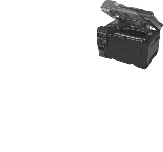
1. Open the print cartridge door.
2. Open the front cover.
ENWW |
Removal and replacement procedures |
9 |

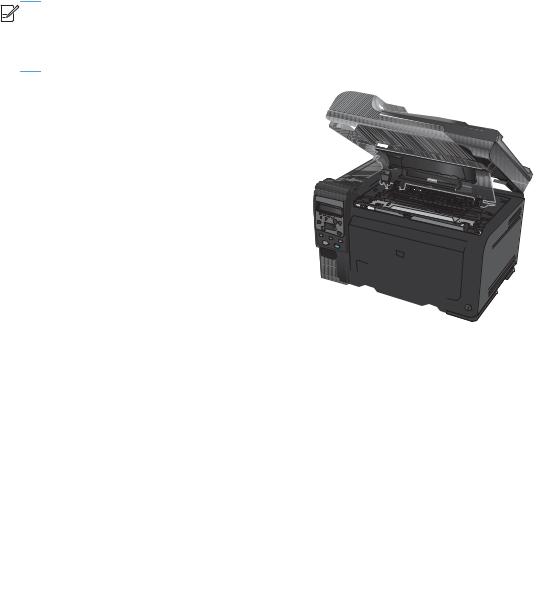
3.Lift the two levers that hold the imaging drum.
4.Remove the old imaging drum.
NOTE: Make sure that you store the removed imaging drum away from strong light. HP recommends that you cover the imaging drum while servicing the product.
10 Chapter 1 Removal and replacement |
ENWW |
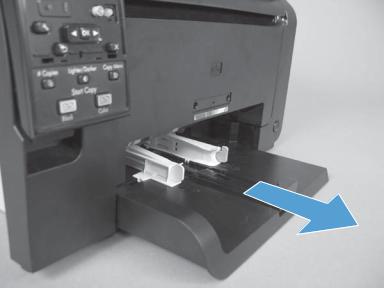
Input tray
Pull the tray away from the printer to remove.
Figure 1-4 Remove the tray
ENWW |
Removal and replacement procedures 11 |

Secondary transfer roller
CAUTION: Do not touch the black spongy part of the roller. Skin oils might cause print-quality problems.
1.Open the rear door.
2.Release two clips (callout 1), and then remove the roller from the product.
Figure 1-5 Remove the secondary transfer roller
1
12 Chapter 1 Removal and replacement |
ENWW |
Separation pad assembly
1.Turn the product face up.
WARNING! The ADF portion of the document feeder is not captive and can open when the product is placed face up. Make sure that you support the ADF when handling the product.


 NOTE: Dirt and debris can scratch the surface of the product. Make sure that you place the product face up on a clean work space or on a clean soft cloth.
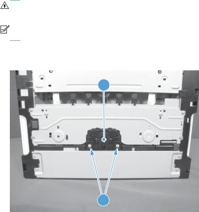
2.Remove two screws (callout 1) and the separation pad assembly (callout 2).
Figure 1-6 Remove the separation pad assembly (1 of 1)
2
1
ENWW |
Removal and replacement procedures 13 |

Pickup roller
Before proceeding, remove the following components:
●Separation pad assembly. See Separation pad assembly on page 13.
●Right cover assembly. See Right cover on page 16.
●Left cover assembly. See Left cover on page 17.
Rotate the pickup roller to the service position
To gain access to the roller locking tabs you must rotate the roller to the correct position for removal.
1.When the product is in the Ready state, press and hold the Auto-On/Auto-Off (power) button for about seven seconds or until the Ready light turns off.

 TIP: Optionally, unplug the power cord, and then plug the cord back in.
2.Make sure that one sheet of paper is loaded in the input tray.


 NOTE: If more than one sheet of paper is loaded in the tray, this procedure will not be successful.
3.Press and release the Auto-On/Auto-Off (power) button and within two seconds press and hold down the cyan cartridge button. Hold the cyan button down for about five seconds, or until the initialization process begins.


 NOTE: Immediately after the Auto-On/Auto-Off (power) button is pressed, all of the control panel lights illuminate briefly (for about two seconds). You must press the cyan cartridge button while the lights are illuminated.
4.When the product finishes initializing, the roller rotates into the removal position. Turn the product off. Unplug the product before removing any components.


 NOTE: When the roller is in the removal position, the sheet of paper will have been pulled into the paper path by about 12 mm (.5 in). This is visual confirmation that the roller has rotated to the removal position.
14 Chapter 1 Removal and replacement |
ENWW |
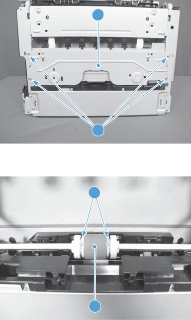
Remove the pickup roller assembly
1.Remove four screws (callout 1) and the lower stay part (callout 2).
Figure 1-7 Remove the pickup roller assembly (1 of 2)
2
1
2.Release two tabs (callout 1) and remove the pickup roller (callout 2).
Figure 1-8 Remove the pickup roller assembly (2 of 2)
1
2
ENWW |
Removal and replacement procedures 15 |

Covers and document feeder
Right cover
1.Open the document feeder.
2.Remove one screw (callout 1), and then starting at the rear vertical edge, release six tabs (callout 2) and remove the right cover.


 NOTE: Before proceeding, take note of the locations of the tabs (callout 1) on the back side of the cover. See Figure 1-10 Remove the right cover (2 of 2) on page 16.
Figure 1-9 Remove the right cover (1 of 2)
2
1
Figure 1-10 Remove the right cover (2 of 2)
1 
16 Chapter 1 Removal and replacement |
ENWW |
Loading...