


Designjet Z5200ps Photo
Table of contents
 Loading...

Notices
Warranty
The information contained in this
document is subject to change without
notice.
Hewlett-Packard makes no warranty
of any kind with regard to this
material, including, but not limited to,
the implied warranties of
merchantability and fitness for a
particular purpose.
Hewlett-Packard shall not be liable for
errors contained herein or for incidental
or consequential damages in connection
with the furnishing, performance, or use
of this material.
WARNING! The procedures described
in this manual are to be performed by
HP-qualified service personnel only.
Electrical Shock Hazard
Serious shock hazard leading to death or
injury may result if you do not take the
following precautions:
●
Ensure that the ac power outlet
(mains) has a protective earth
(ground) terminal.
●
Disconnect the Printer from the
power source prior to performing
any maintenance.
●
Prevent water or any other liquids
from running onto electrical
components or circuits, or through
openings in the enclosure.
Electrostatic Discharge
Refer to the beginning of
Diagnostic
Menu on page 73 of this manual, for
precautions you should take to prevent
damage to the Printer circuits from
electrostatic discharge.
Safety Symbols
General definitions of safety symbols are
given immediately after the table of
contents.
WARNING! The Warning symbol calls
attention to a procedure, practice, or the
like, which, if not correctly performed or
adhered to, could result in personal
injury. Do not proceed beyond a Warning
symbol until the indicated conditions are
fully understood and met.
CAUTION: The Caution symbol calls
attention to an operating procedure,
practice, or the like, which, if not correctly
performed or adhered to, could result in
damage to or destruction of part or all of
the product. Do not proceed beyond a
Caution symbol until the indicated
conditions are fully understood and met.
Content Management Department,
Barcelona Division,
Hewlett-Packard Espanola, S.A.
Avda. Graells, 501
08190 Sant Cugat del Valles
Spain
ENWW iii

Using this Manual
Purpose
This Service Manual contains information necessary to test, calibrate and service:
●
HP Designjet Z5200 Photo Printer 44 inch (Model CQ 11 3A)
For information about using this product, refer to the corre sponding User a nd Quick Reference Gui des.
Readership
The procedures described in this Service Manual are to be performed by HP Certified service personnel
only.
Part Numbers
Part Numbers for Printer options, accessories and service parts are located in
Parts and Diagrams
on page 151.
Conventions
A small arrow
indicates a link to other parts of the Service Manual where you can find in fo rmation
related to the topic you are consulting.
ENWW v

Table of contents
1 Ink Supplies Troubleshooting & Print Quality
Introduction ..................................................................... .................................... .................................. 2
Troubleshooting System Error Codes .................................................................................................. 2
Performing a Service Test on a failed Assembly ..................................... ................................... .......... 2
Performing the Necessary Service Calibrations ................................................................................... 2
Solving Ink Supplies Problems .................................. .. ..... ..... .. ..... ..... .. ..... ..... .. ..... ..... .. ..... ..... .. ............. 3
Solving Print Quality Problems ................................................ ............................. ................................ 3
Using the Front Panel ......................................................................... .................................................. 3
The Printer does not Power ON ........................................................................................................... 4
The Printer Continuously Rejects Printheads ........................... ................................... ......................... 4
What to do if the Front Panel is blank .................................................................................................. 5
Cover Sensors are not Working ........................................................................................................... 6
The Line Sensor has Problems Detecting Media ................................................................................. 6
Problems with Color Accuracy ............................................................................................................. 6
Troubleshooting Media Jams/Printhead Crashes ................................................................................ 6
Banding at variable extreme environmental conditions ........................................................................ 7
Worm marks on HP Coated media with light area fills ......................................................................... 7
Solving Media-Handling Problems ....................................................................................................... 7
What to do when plastic parts on the Media Basket become damaged during printer setup ............... 8
Solving Ink Supplies problems ............................................................................................................. 9
Ink Cartridges ...................................................................................................................... 9
Available Ink Cartridges ..................... ... .......................... ........................... .......................... 9
Printheads .......................................................................................................................... 10
Available Printheads .......................................................................................................... 10
General Information About the Ink Supplies ...................................................................... 10
General Precautions When Handling Ink Supplies ............................................................ 11
When Should You Replace the Ink Supplies? ................................................................... 11
Ink Cartridge Levels, Information, and Replacement ......................................................................... 11
Ink Cartridge Levels ............................ .... ... .... ..... .. ..... .... ... .... .... ... .... ..... .. ..... .... ... .... ..... .. .... 11
Obtaining Ink Cartridge Information ....................... .. .......................... ......................... ....... 12
Changing an Ink Cartridge .......................... ........................... ........................... ................. 13
Printhead Information, Replacement and Alignment ................................................................ .......... 15
Obtaining Printhead Information ........................................................................................ 15
Changing a Printhead ........................................................................................................ 16
Aligning Printheads ................................. ..... ....... ....... ..... ....... ....... .... ........ ...... .... ....... ........ 18
Ink Cartridge and Printhead Status Messages ................ .. ............................ ........................... .......... 20
Ink Cartridge Status Messages ............................................................... ........................... 20
ENWW vii

Printhead status messages ............................................................................................... 20
Solving Ink Supplies Problems ............................... ...... . ..... ..... .. ..... ..... .. ..... ..... .. ..... ..... .. ..... ..... ....... ... . 21
You Cannot Insert the Ink Cartridge Into the Printer .................................. ........................ 21
You Cannot Insert the Printhead Into the Printer ............................................................... 21
The front panel says to reset or replace a printhead ......................................................... 21
Maintaining and Cleaning the Printheads ................................................................ ........................... 22
Clean the printheads .......................................... ... ....... ..... ... ..... ....... .. ...... ..... .... ...... ..... .... .. 22
Flex Contacts Cleaning Tool ............................... ... .................................. .......................... 22
Print Quality ................................... .. ..... ..... ... ..... ...... . ..... ...... ... ..... ..... .. ..... ..... .. ..... ..... .......................... 23
Print Quality Troubleshooting Actions ........................................................ ........................ 23
The Service Image Quality Diagnostic Print ............................................... ............................ ............ 24
What is the Service Image Quality Diagnostic Print? ........................................................ 24
Considerations for Printing the Diagnostic Print ................................................................ 24
Printing the Diagnostic Print .............................................................................................. 24
Reading the Diagnostic Print Results ........................ ............................ ............................. ................ 25
Diagnostic Part 1: Printhead Reliability ......................................................... ..................... 25
Diagnostic Part 2: Printhead Alignment ............................................................................. 26
Diagnostic Part 3: Printheads & Paper Advance ............................................................... 28
No Printing Defects Found in the Diagnostic Print ................................ ............................. 29
The Advanced Diagnostic Prints ........................................................................................................ 29
What are the Advanced Diagnostic Prints? ....................................................................... 29
Printing the Advanced Diagnostics Print .............................................................. .............. 30
Reading the Advanced diagnostic Print Results ................................................................................ 30
Paper Advance .................................................................................................................. 30
Printhead Alignment .......................................................................................................... 33
Nozzle Health .................................................................................................................... 34
Force Drop Detection .......................................... .... ..... ...... .. ....... ..... ... ..... ....... .. ...... ..... .... .. 35
Troubleshooting Print Quality Problems .............................. ... .... .... .... ... ..... ... .... ..... .. ..... ..... .. ..... ......... 36
Print Quality General Advice .............................................................................................. 36
Horizontal Lines Across the Image (Banding) ................................................................... 36
Lines are Missing, Too Thin, or Too Thick ................................ ... ................................ ...... 37
Problems with Stepped Lines ............................................................................................ 37
Lines are Printed Double or in Wrong Colors .................................................................... 38
Lines are discontinuous ..................................................................................................... 38
Lines are Blurred (Ink Bleeds from Lines) ......................................................................... 39
Problems with Graininess .................................................................................................. 39
Paper is not Flat ................................................................... ................................... ........... 40
Print Scuffing or Scratching when Touched .............................. ..... ... ..... ..... .... ..... ...... .. ...... 41
Ink marks on the paper ...................................................................................................... 41
Problems with the Edges of objects ................................ .................................. ................. 42
Bronzing ............................................................................................................................. 42
Black and white prints do not look neutral ......................................................................... 43
Horizontal lines at the end of a cut sheet print ............................ .. ................................. .... 43
Vertical lines of different colors ................................................... .......................... ............. 43
White spots on the print ..................................................................................................... 43
Problems with Color Accuracy ................................................. .......................... ................ 43
Output Only Contains a Partial Print ................... .......................... .......................... ........... 44
viii ENWW

Problems with Image Clipping ........................................................................................... 44
Some objects are missing from the printed image ......................................... ... ... .............. 45
A PDF file is clipped or objects are missing ................................................................. ...... 45
2 System Error Codes
Introduction ..................................................................... .................................... ................................ 46
Continuable and Non-Continu abl e Erro r Codes ................................................................................. 47
System Error Code Brief Descriptions ................................................................................................ 47
System Error Codes - Full Descriptions ............................................................................................. 50
3 Diagnostic Menu
Introduction ..................................................................... .................................... ................................ 74
Diagnostics - Self Test .................. .. ........................... ........................... ............................ . 74
Service Tests (Diagnostics) ................................ ... ....... ...... .. ....... ....... . ....... ....... . ....... ....... .. ............. .. . 74
Entering the Service Tests Menu ............................................................. .......................... 76
1. Scan Axis ...................................................................................................... 76
2. Paper Drive .................................................................................... ............... 87
3. Electronics Module .......................................... ........................ ...................... 90
4. Carriage Assembly ........................................... ......................... .................... 95
5. Sensors ....................................................................................................... 101
6. Color Sensor (ESP) ............................ .. . .. .. .......................... .. .. . .. . .. .............. 104
7. Ink Delivery System (IDS) ........................................................................... 106
8. Service Station ............................................................................................ 110
9. I/O Information .................................................................... ........................ 117
10. Unit Information ......................................................................................... 117
11. EEROM Reset ........................................................................................... 119
12. Set Unit Configuration ............................................................................... 120
13. Error 71:19 Recovery ................................................................................ 120
.......................................................................................................................................................... 123
4 Service Menu
Entering the Service Utilities Menu .................................................................................................. 124
Introduction ...................................................................................................................... 125
......................................................................................................................... 126
1. Turn Drive Roller .......................................................................................................... 126
2. Purge Tubes ................................................................................................................ 128
3. Set SN ......................................................................................................................... 130
4. Reset Life Counters ..................................................................................................... 131
5. Diagnostic Print ............................................................................................................ 132
6. Set Date and Time ....................................................................................................... 132
7. Enable/Disable Firewall ............................................................................................... 133
8. Enable/Disable Sleep Mode ........................................................................................ 134
9. SNMP Language Write Access ................................................................................... 135
10 Borderless Cut Distance ............................................................................................. 137
Service Calibrations ......................................................................................................................... 138
Entering the Service Calibrations Menu .......................................................................... 139
ENWW ix

Scan Axis Calibration ....................................................................................................... 139
Service Station Calibration .............................................................................................. 140
Paper Advance Calibration .............................................................................................. 140
Drop Detector Calibration ................................................................................................ 145
Line Sensor Calibration ................................................................................................... 146
Carriage PCA .................................... ...... ..... .... ..... ....... . ....... ..... ... ..... ....... ... ...... ..... ... ....... 149
Color Sensor (ESP) Calibration ............................... ...... ... ... ...... ... ..... .... ... ..... .... ... ...... ... .. 149
5 Parts and Diagrams
Printer Support ................................................................................................................................. 152
Center Covers (Front) ...................................................................................................................... 153
Center Covers (Rear) ................... .. ......................... ........................ ......................... ........................ 154
Right Cover ...................................................................................................................................... 155
Left Cover ............................................................ ............................... .............................................. 156
Right Hand Assemblies ..................... ........................ .......................... ........................ ..................... 157
Left Hand Assemblies ...................................................................................................................... 158
Carriage Assembly .......................... .... ..... . .... ..... .. .... .... .. .... ..... . ..... .... .. ..... ... .. ..... .... .. ..... ... ............. ... 159
Scan-Axis Assemblies ............................... .... ........ ....... ..... ....... ........ .... ........ ....... ..... ....... ................. 160
Paper Path Assemblies (Front) ........................................................................................................ 161
Paper Path Assemblies (Rear) ................................ ..... ... .... ..... ... .... ..... ... .... .... .... .... .... .... .... .... ......... 162
Tools 1 ........................................................................ .................................... .................................. 163
Tools 2 ........................................................................ .................................... .................................. 164
Miscellaneous Parts ......................................................................................................................... 165
6 Removal and Installation
Introduction ....................................................................................................................................... 169
Safety Precautions ....................................... .. ....... ..... ... ..... ....... .. ...... ...... ... ..... ....... . ....... .. 169
Electrostatic Discharge (ESD) Precautions ..................................................................... 169
Required Tools ................................................................................................................ 169
Service Calibration Guide to Removal and Installation .................................................................... 170
Using the Service Calibration Guide ........................ .......................... ......................... ..... 170
The Service Calibration Matrix ................................ ................................ ......................... 171
Performing the Service Calibrations and Diagnostic Tests ............................. .. ............... 172
Window ............................................................................................................................................. 174
Front Cover ...................................................................................................................................... 177
Media Output Assembly ................................................................................................................... 178
Right Front Trim ............................................................................................................................... 179
Left Front Trim ......................................................... .............................. ........................................... 181
Right Ink Cartridge Door ................................................................................................................... 182
Left Ink Cartridge Door .............................................. ......................... ......................... ..................... 183
Right Cover ...................................................................................................................................... 185
Left Cover ............................................................ ............................... .............................................. 188
Rear Tray ......................................................................................................................................... 194
Rear Cover .......................... ..... .... ... .... .... ... ... ..... .. .... ..... . ..... .... .. ..... .... ... ... ..... .. .... ..... . ........... ............ 195
Media Lever ................................... ..................................... ..................................... ......................... 196
Media Lever Position Sensor ........................................................................................................... 198
x ENWW

Cutter Assembly ............................ .. ..... ... ... .... .... .. .... .... ... .... .... ... ... ..... .. ... ...... . .... ..... .. .... ................... 199
Right Rear Tray Support .................................................................................................................. 200
Left Rear Tray Support ..................................................................................................................... 201
Front Panel ....................................................................................................................................... 203
Top Cover .............................. .. ..... .... .. .... ..... .. .... .... .. ..... .... ... .... .... .. .... ..... .. ..... ... ... .... .... ......... ... ......... 205
Window Position Sensor .................................................................................................................. 208
Ink Supply Tubes Support Rail ......................................................................................................... 209
Service Station ................................................................................................................................. 214
Drop Detector ................................................................................................................................... 217
Aerosol Fan Assembly ..................................................................................................................... 219
PrintMech PCA ................................................................................................................................. 220
Pen to Paper Space (PPS) Solenoid ................................................................................................ 221
Spindle ..................... .......................................................... .............................................................. 223
Left Spindle Holder ........................................................................................................................... 224
Right Spindle Holder ........................................................................................................................ 224
Clean Out Assembly ................................................ ........................ .......................... ....................... 225
Out Of Paper Sensor ...................................................................................... .................................. 226
Left Roll Guide ......................... .. .......................... ......................... ......................... ........................... 229
Right Roll Guide ............................................................................................................................... 230
Encoder Strip (with spring and attachment nut) ............................................................................... 231
Clean Encoder Strip Procedure .............................................. ....................... ........................ ........... 234
Encoder Strip ................................................ ......................... .......................... ................................. 236
Trailing Cable ................................................................................................................................... 237
Carriage Assembly (with or without Trailing Cable) ......................................................................... 244
Carriage Rear Bushing ..................................................................................................................... 254
Belt Assembly ............................ .. .... ..... .. .... .... .. ..... .... . ..... .... .. ..... .... .. .... ..... .. .... ..... . .... ......... .............. 256
Scan-Axis Motor ............................................................................................................................... 257
Carriage Rail Oiler ............................................................................................................................ 260
Color Sensor (ESP) ......................... . .... .... . .... .... .. ... .... .. ... .... .. ... .... .. .... ... .. ... .... .. ... .... . .... ... .. ............... 262
Line Sensor ...................................................................................................................................... 267
Carriage Cover (includes Carriage Latch) ........................................................................................ 272
Carriage PCA ................................................................................................................................... 276
Right Ink Supply Station ................................................................................................................... 280
Left Ink Supply Station ..................................................................................................................... 284
Ink Supply Tubes ................................................. ......................... ......................... ........................... 288
Formatter ............................................................. ................................................... .......................... 296
Hard Disk Drive .................................... ..................................................... ....................................... 297
Electronics Module (Main PCA and PSU) ........................................................................................ 298
Starwheel Assembly ......................................................................................................................... 301
Print Zone Overdrive ........................................................................................................................ 302
Left Spittoon ..................................................................................................................................... 306
Encoder Disk and Encoder Sensor .................................................................................................. 308
Media Advance Drive ....................................................................................................................... 311
Pinchwheel Assembly ...................................................................................................................... 314
Pinch Roller .....................................................................................................................
................. 319
Left Starwheel Lifter ......................................................................................................................... 320
Right Starwheel Lifter ....................................................................................................................... 322
ENWW xi

Starwheel Motor ............................................................................................................................... 325
Full Bleed Foam ............................................................ ............................. ...................................... 326
7 Preventive Maintenance
Preventive Maintenance ................................... .. ..... ..... .. ..... ..... ... .... ..... ... ..... ..... .. ..... ..... .. ..... ............ 328
Moisture on the Printer .................................................................................................... 328
Noisy Carriage Bushing .................................... ....... ..... ... ..... ....... .. ...... ...... ... ..... ..... ... ...... 328
Belt Swelling ................................ .. ..... ..... . ...... ..... . ...... . ..... ..... .. ..... ..... .. ..... .... ... .... ..... ... .... 328
Cleaning the Printer ............................. ... ................................... .................................. .... 328
Carriage Assembly Lubrication ...................... ..... .... .. ..... ... ... .... ..... .. .... ..... . ..... .... .. ..... .... ... 328
General Cleaning ........................... ..... .... ... ..... ... ..... ... .... ..... .. ..... ..... .. ..... .... ... .... ..... .. .... .... 329
Cleaning the Drive Roller and Overdrive ............................. ............................. .. .. ........... 329
Level of Printer Usage ..................................................................................................... 329
Preventive Maintenance Kits .......................... ... ............................. ............................. ..................... 330
Preventive Maintenance Kit #1 ........................ ... .................................. ........................... 330
Preventive Maintenance Kit #2 ........................ ... .................................. ........................... 331
8 Printer menu Map
xii ENWW

1 Ink Supplies Troubleshooting & Print
Quality
●
Introduction
●
Troubleshooting System Error Codes
●
Performing a Service Test on a failed Assembly
●
Performing the Necessary Service Calibrations
●
Solving Ink Supplies Problems
●
Solving Print Quality Problems
●
Using the Front Panel
●
The Printer does not Power ON
●
The Printer Continuously Rejects Printheads
●
What to do if the Front Panel is blank
●
Cover Sensors are not Working
●
The Line Sensor has Problems Detecting Media
●
Problems with Color Accuracy
●
Troubleshooting Media Jams/Printhead Crashes
●
Banding at variable extreme environmental conditions
●
Worm marks on HP Coated media with light area fills
●
Solving Media-Handling Problems
●
What to do when plastic parts on the Media Basket become damaged during printer setup
●
Solving Ink Supplies problems
●
Ink Cartridge Levels, Information, and Replacement
●
Printhead Information, Replacement and Alignment
●
Ink Cartridge and Printhead Status Messages
●
Solving Ink Supplies Problems
●
Maintaining and Cleaning the Printheads
●
Print Quality
●
The Service Image Quality Diagnostic Print
ENWW 1

●
Reading the Diagnostic Print Results
●
The Advanced Diagnostic Prints
●
Reading the Advanced diagnostic Print Results
●
Troubleshooting Print Quality Problems
Introduction
This chapter will guide you through the relevant steps to take when troubleshooting the printer.
Troubleshooting System Error Codes
Chapter 2, System Error Codes on page 46 contains a list of system error codes and their respective
descriptions and recommended corrective actions. Only try one recommended action at a time and
check if the error code has disappeared.
If you have an error code which is not documented in this Service Manual or you have an error which
you cannot resolve, then report the error to the HP Response Center or the nearest HP Support Office.
When reporting the error, have the following information ready:
●
Model and Serial Number of the printer
●
Which firmware revision the printer is using (See Note below). Check firmware in Utilities/
Statistics/Code rev.
●
The complete error number (See Note below).
●
The Service Configuration Print.
●
The Current configuration sheet.
●
Which software application the customer is using (name, version, etc.).
NOTE: When reporting the System Error Code, make sure that you supply the full Error Code
and the firmware version. Without this information, HP Support Personnel cannot help you.
Performing a Service Test on a failed Assembly
If possible, always perform a Service Test on the component/assembly that you are about to replace,
just to make sure that is the component/assembly that has failed.
NOTE: If the test on that component/assembly passes, you should NOT replace it.
For information on the Service Tests and how to use them see Diagnostic Menu on page 73 & Service
Menu on page 124.
Performing the Necessary Service Calibrations
Is the printer calibrated correctly after replacing a component? For information on the Service
Calibrations and how to use them see Chapter 5, Service Calibrations.
NOTE: Remember that certain Calibrations are required even if an Assembly has been
disassembled to gain access to another Assembly or Component.
2 Chapter 1 Ink Supplies Troubleshooting & Print Quality ENWW
Solving Ink Supplies Problems
For information on solving Ink Supplies problems see Solving Ink Supplies problems on page 9 in
this section.
Solving Print Quality Problems
For information on solving Print Quality problems see Print Quality on page 23 in this section.
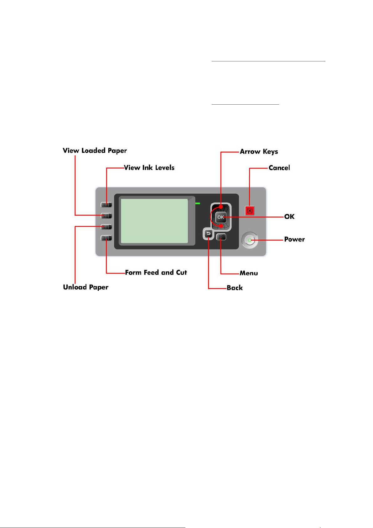
Using the Front Panel
Below is a diagram of the front panel.
Key Function
●
Arrow Keys
Use the Arrow keys to scroll through a menu or toggle between YES or NO when prompted.
●
Cancel
Use the Cancel key to abort or stop a procedure or reject test results.
●
OK
Use the OK key to select a menu option.
●
Power
Use the Power key to turn the printer ON and OFF.
●
Menu
Use the Menu key to enter the main menu.
●
Back
Use the Back key to go back to the previous menu or reject test results.
ENWW Solving Ink Supplies Problems 3

Service Key Combinations
●
Diagnostic mode
With the printer OFF, press and hold the UP and OK keys. While hol ding the Up and OK keys down,
press and hold the Power key to turn on the printer. Hold all three keys until the Power key stops
flashing, usually about 5 seconds.
●
Service Menu (Service Engineers Only)
From the main menu, press and hold the Up and Cancel keys.
●
Service Menu (For users)
From the main menu, press and hold the Down and Cancel keys.
The Printer does not Power ON
1. Check that the power cord is connected correctly to the Printer and to the Power Socket.
2. Check that the Power Switch on the BACK of the Printer is in the ON position.
3. Check to see the LED on the Front Panel Power Switch are On.
4. Check that the Front-Panel Cable is correctly connected to the Electronics Module. Also make sure
that the Front-Panel cable is not damaged.
5. Replace the Power Supply Unit
Refer Electronics Module (Main PCA and PSU) on page 298.
The Printer Continuously Rejects Printheads
1. Clean the flex contacts on the Printhead and in the Carriage Assembly using the Carriage
Interconnect Wiper (Refer to
Flex Contacts Cleaning Tool on page 22) and try again.
2. If ALL the Printheads are rejected (the status message on th e F ron t Pa ne l do es NOT show "OK"
for ALL the Printheads) then perform the Electronic Module Test
Refer 3. Electronics Module
on page 90.
4 Chapter 1 Ink Supplies Troubleshooting & Print Quality ENWW
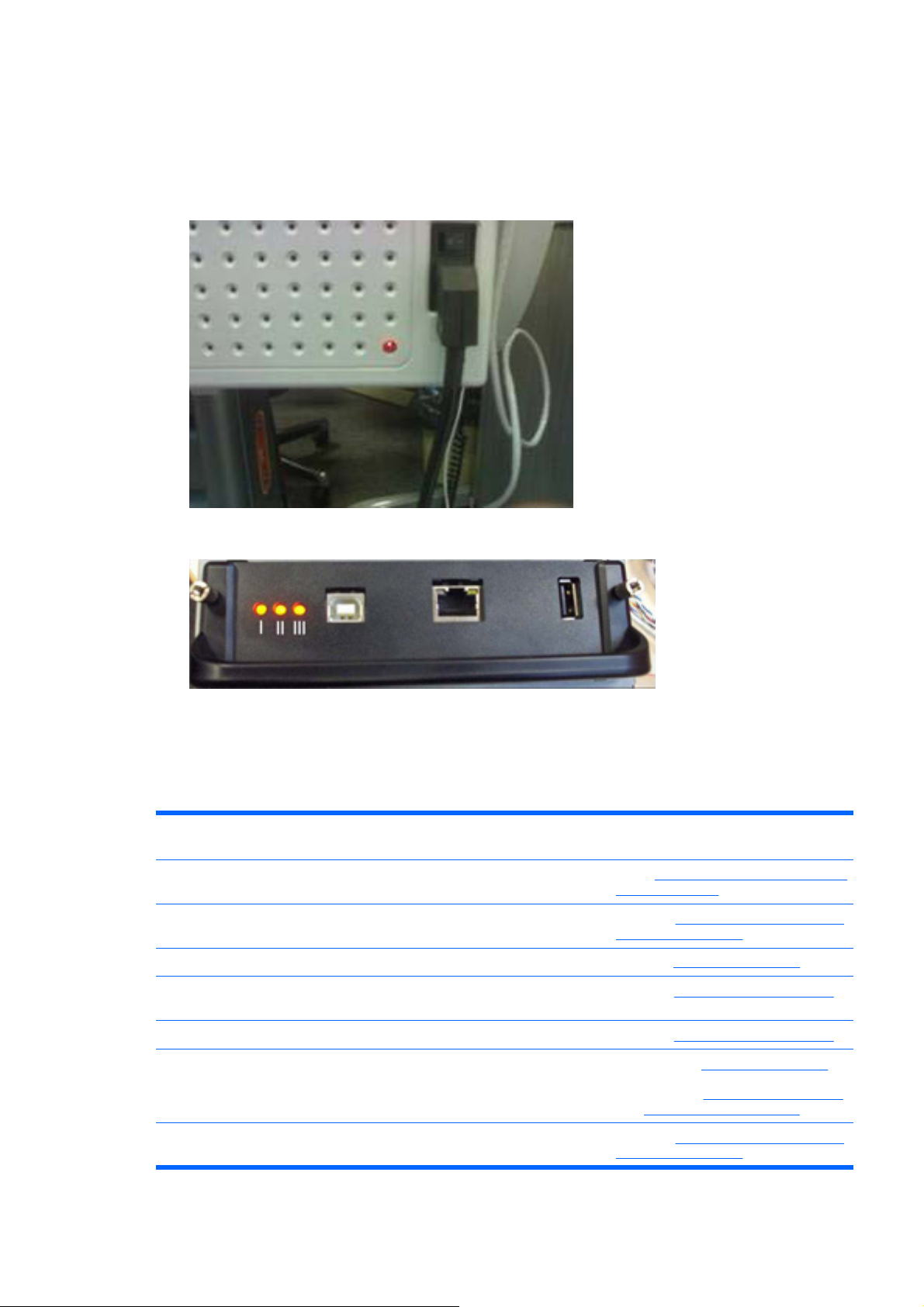
What to do if the Front Panel is blank
The LEDs of the formatter (visible through the cover) and the power supply can help you troubleshoot
a problem when the Front Panel is blank.
1. The following image shows the Power Supply LED, looking through the cover.
2. The following image shows the Formatter LEDs, which are marked I, II and III.
▲
Use the following table to interpret the LEDs and find the so urce of the problem. Remember that
you should read these LEDs when you push the Power button. Some combinations may require
the replacement of two or more components. In th is case, always replace one component at a time.
Test the printer to see if the problem has disappeared (ch eck the LEDs again). If the same LED
sequence continues, replace the next component indicated in the table.
Power
Supply LED
Formatter
LED 1
Formatter
LED 2
Formatter
LED 3
Front Panel
Status
Solution (part replacement)
1 Off Off Off Off Off Power Electronics Module (Main PCA and
PSU) on page 298
2 On Off Off Off Off Main PCA Electronics Module (Main PCA
and PSU) on page 298
3 On On Off N/A N/A Formatter Formatter on page 296
4 On On
(Flashing)
Off Off N/A Hard Disk Hard Disk Drive on page 297
5 On On On (flashing) Off N/A Hard Disk Hard Disk Drive on page 297
6 On On On Off N/A 1. Formatter Formatter on page 296
2. Main PCA
Electronics Module (Main
PCA and PSU) on page 298
7 On On On On (flashing) N/A Main PCA Electronics Module (Main PCA
and PSU) on page 298
ENWW What to do if the Front Panel is blank 5

8 On On On On Front Panel
(Light on)
1. Front Panel Front Panel
on page 203
2. Formatter
Formatter on page 296
3. Main PCA
Electronics Module (Main
PCA and PSU) on page 298
4. Front Panel Cable
Front Panel
on page 203
9 On On On On Off Front Panel Front Panel on page 203
Cover Sensors are not Working
1. Perform the Sensors Test Refer 5. Sensors on page 101.
2. Check if the cable for the faulty sensor is not damaged and is connected correctly.
3. Replace the faulty Sensor.
The Line Sensor has Problems Detecting Media
1. Check the type of media that is being used since the Line sensor may have problems detecting
transparent media or some types of Non-HP media. Try loading white HP media in to the Printer
and check if the Line sensor detects it.
2. The Line Sensor is not calibrated correctly. Perform the Line Sensor Calibration
Refer Line
Sensor Calibration on page 146.
3. The Line Sensor is damaged or faulty. Replace the Line Sensor
Line Sensor on page 267.
Problems with Color Accuracy
The Color Sensor (ESP) is a powerful tool unique to the Z series printers to maintain color accuracy. If
you notice any problems with colors, perform the Color Sensor (ESP) calibration. Refer to
Color Sensor
(ESP) Calibration on page 149.
Troubleshooting Media Jams/Printhead Crashes
The failure modes "media jam" and "head crash" are grouped together because in many cases a media
jam causes the media to lift up into the Carriage path and cause a Printhead crash, thus causin g many
media jam failures to be reported as head crashes.
1. Did the media jam occur when loading media?
●
If the client has had media jams, it is common for pieces of media to get stuck in the media
path. Clear the media path.
NOTE: When clearing a media jam, sometimes media is stuck in the paper path. To clear this,
you must lift the Media Lever and insert thicker media into the p ap er pa th t o push ou t th e media
that is still stuck there.
2. Is the customer using non-HP media?
●
The use of non-HP media can easily be the cause of media jams and head crashes (espec ially
head crashes because HP media is specially formulated to avoid cockle, one of the primary
causes of head crashes). If the media is not HP approved, advise the customer to use HP
media and check to see if the problem is now solved.
6 Chapter 1 Ink Supplies Troubleshooting & Print Quality ENWW

Banding at variable extreme environmental conditions
Since the Accuracy Calibration has been done at normal environmental conditio ns, printing in extreme
environmental conditions will cause banding because the advan ce of th e Media Advance Roller does
not correspond to the same conditions that the calibra tio n was done in. To solve the problem, try the
following:
Perform the Accuracy Calibration in the new environmental conditions (Refer to the User’s Guide).
Worm marks on HP Coated media with light area fills
Light bands (S-shaped) in Paper axis direction where light area fills are printed, causing unacceptable
Image Quality defect.
●
Print the Service Configuration Print and check if the level of Humidity is very low (below 30%).
Increasing humidity may help in reducing the severity of th e p ro blem.
NOTE: The media is causing the problem and NOT the Printer. Do not attempt to try and replace
Printer parts to solve this problem.
Solving Media-Handling Problems
The Front Panel indicates that media is misalig ne d or incorrectly positioned.
Roll media
●
The roll may be loaded the wrong way. The paper should load over the roll toward you.
●
Check that the paper is correctly loaded onto the spindle.
●
The paper may be loaded at an angle. The right-hand edge must be aligned with the blue line on
the Print Platen.
NOTE: Ensure that the paper is wrapped tightly on the roll. This is a very imp ortant step to rememb er
because if this is not done, the media may be loaded at an angle, causing the media to be rejected.
Sheet media
●
Always load sheet media using the Rear Input Tray. Do NOT load the media as you would load
roll media.
●
It must be loaded with the right-hand edge against the blu e line on th e Prin t Platen.
●
The media may be crumpled or warped or may have irregular edges.
●
If hand-cut media is used, the edges may not form a right-angle or they may be rough. If possible,
hand-cut media should not be used. Only purchased sheet media should be used in the Printer.
●
If you have problems with paper jams, check that the Overdrive is not obstructed by bits of paper
or using the Turn Drive Roller Service Utility
1. Turn Drive Roller on page 126.
ENWW Banding at variable extreme environmental conditions 7
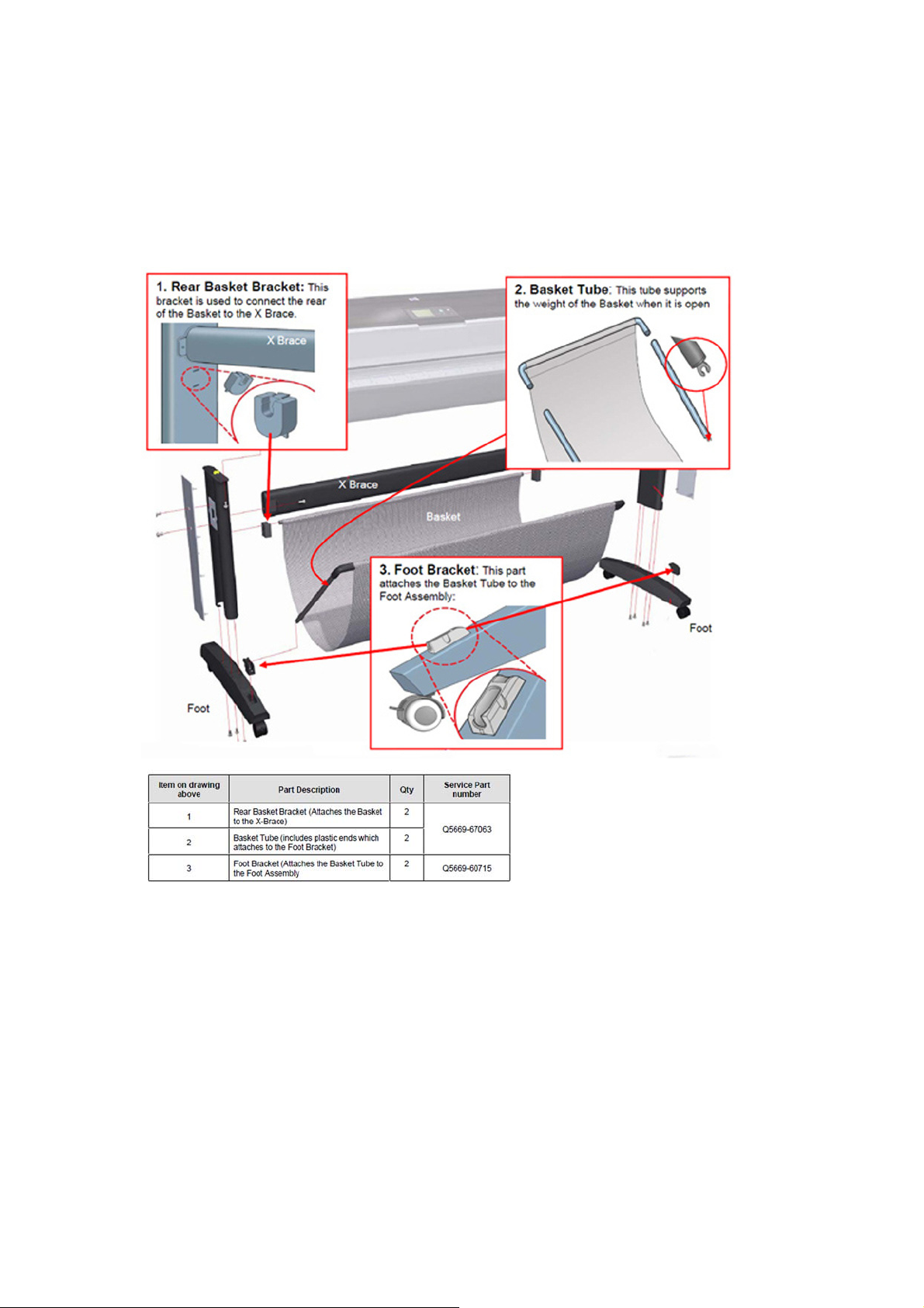
What to do when plastic parts on the Media Basket become
damaged during printer setup
The following information explains what to do if one or more of the back plastic brackets or the Basket
Tube becomes broken. The information helps to identify which service parts to order as replacements.
There are three plastic parts that could break during printer installation and need replacing. Use the
pictures below to identify with the customer which part needs replacing (numbers 1, 2 or 3).
8 Chapter 1 Ink Supplies Troubleshooting & Print Quality ENWW
Solving Ink Supplies problems
What are Ink Supplies?
For each of the ink colors used in the printer, there are two components, th e Printhead and Ink Cartridge.
These components are called Ink Supplies.
Ink Cartridges
The printer's Ink Cartridges provide ink to the Printheads. The color Ink Cartridges supplied with the
printer have a capacity of 69ml but optional 130 ml and 30 0 ml are also ava ilab l e.
The Ink Cartridges require no maintenance or cleaning. As long as each Ink Cartridge is inserted
correctly into its slot, the ink will flow to the Printheads. Because the Printheads control the amount of
ink transferred to the page, you will continue to see high quality printing results that require no
maintenance or cleaning. As long as each Ink Cartridge is inserted correctly into its slot, the ink will flow
to the Printheads. Because the Printheads control the amount of ink transferred to the page, you will
continue to see high quality printing results even when the ink levels are getting low.
The front panel displays the status of the Ink Cartridge. Using the front panel, detailed information can
be checked on the Ink Cartridges.
Available Ink Cartridges
Color Part number 69ml Part number 130ml Part number 300ml
HP 70 Matte Black C9436A C9448A CN635A
ENWW Solving Ink Supplies problems 9
HP 70 Photo Black C9437A C9449A CN633A
HP 70 Light Gray C9439A C9451A CN634A
HP 70 Cyan C9440A C9452A CN636A
HP 70 Magenta C9441A C9453A CN629A
HP 70 Yellow C9442A C9454A CN630A
HP 70 Light Magenta C9443A C9455A CN631A
HP 70 Light Cyan C9389A C9390A CN632A
Printheads
The Printheads are extremely durable an d d o n ot need to be replaced every time an Ink Cartridge is
replaced. They are independent of the Ink Cartridges and will continue giving excellent image quality
results even if the Ink Cartridges are low on ink.
If you notice a decline in print quality such as lines or dots missing from text/graphics, go to
Troubleshooting Print Quality Problems on page 36.
Available Printheads
Printhead Type Part number
HP 70 Matte Black & Cyan C9404A
HP 70 Light Magenta & Light Cyan C9405A
HP 70 Magenta & Yellow C9406A
HP 70 Photo Black & Light Gray C9407A
General Information About the Ink Supplies
For optimum results from the printer and modular ink delivery system always follow these guidelines
when handling the ink supplies:
●
Always install the Ink Cartridges and Printheads befo re t he exp ira tion da te , wh ich is o n the
packaging.
●
Install Ink Cartridges and Printheads in their color-coded slots.
●
Follow the instructions on the front panel of the Printer during installation.
●
Avoid unnecessary removal of the Ink Cartridges and Printheads.
10 Chapter 1 Ink Supplies Troubleshooting & Print Quality ENWW

●
When turning off the Printer always use the power Off button on the front panel. The Printheads
are then stored correctly which prevents them from drying out.
●
The Ink Cartridges should never be removed while the printer is printing. They should only be
removed when the printer is ready for you to replace them. The front panel will guide you through
the removal and installation procedure.
General Precautions When Handling Ink Supplies
Use the following precautions when handling Ink Supplies:
NOTE: Do not touch, wipe or attempt to clean the printhead nozzles. This can damage the printhead.
●
Handle the ink supplies with care. In particular the Printhead, which is a hi gh precision de vice and
must be handled carefully.
●
Do not touch the Printhead nozzles.
●
Do not put the Printhead down on the nozzles.
●
Do not be rough when handling the Printheads. Always set them down gently.
●
Do not drop the Printheads.
●
Proper handling will assure optimum performance throughout the Printhead life.
●
Do not touch the end of the Ink Cartridge which is inserted into the printer as there may be a small
amount of ink on the connection.
●
Avoid storing partially used Ink Cartridges on their ends.
When Should You Replace the Ink Supplies?
When to change the ink supplies is mostly determined by you with guidance from the front panel. In
conjunction with the messages displayed in the front panel and the message explanations in this
chapter, you will be able to choose for yourself when is the right time to change the ink supplies.
The Printer will also display the ink level and will tell you when the ink supply is low on ink. This means
you have constantly updated information about the ink supplies.
Ink Cartridge Levels, Information, and Replacement
Ink Cartridge Levels
The front panel displays Ink Levels shown as level bars. These bars represent how much ink is remaining
in the Ink Cartridges: as ink is used up the bars get shorter in length.
There are two methods for checking the ink levels of your Ink Cartridges.
“View Ink Levels” Direct Access Key
●
Pressing the “View ink levels” direct access key on the Front Panel will immediately show you the
ink levels. For more information about direct access keys, refer
Using the Front Panel on page 3.
ENWW Ink Cartridge Levels, Information, and Replacement 11

“View Ink Levels” from the ink menu
●
Choosing the View ink levels options from the Ink menu will immediately show you the ink levels:
Obtaining Ink Cartridge Information
1. Scroll to the Ink Menu icon and press OK
2. In the Ink Menu submenu, scroll to Ink cartridge information and press OK
3. In the Ink cartridge information submenu, scroll to the Ink Cartridge that you want information
on and press OK.
12 Chapter 1 Ink Supplies Troubleshooting & Print Quality ENWW
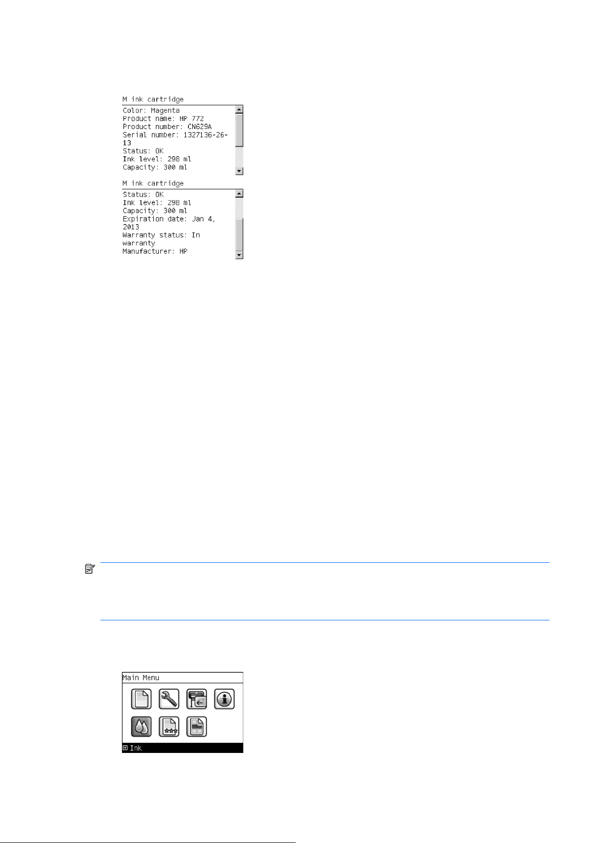
4. The front panel displays information on the selected Ink Cartridge. Use the Arrow keys to scroll
through the information.
The information supplied is:
●
The make of the Ink Cartridge.
●
The product number of the Ink Cartrid ge .
●
The serial number of the Ink Cartridge.
●
The current status of the Ink Cartridge.
●
The current ink level of the ink cartridge in milliliters.
●
Original capacity of the ink cartridge in milliliters.
●
The manufacturer of the Ink Cartridge (hp is recommended).
●
The current warranty status of the Ink Cartridge.
Changing an Ink Cartridge
There are two occasions when you need to remove an ink cartridge:
●
The ink cartridge is very low and you want to replace it with a full cartridge for unattended printin g
(you can use up the remaining ink in the first cartridge at a more convenient time).
●
The ink cartridge is empty or faulty, and you must replace it to continue printing.
NOTE: Do not try to remove an ink cartridge w hile printing. Remove an ink cartridge only if you are
ready to insert another one.
Make sure the printer wheels are locked (the brake lever is pressed down) to prevent the printer from
moving.
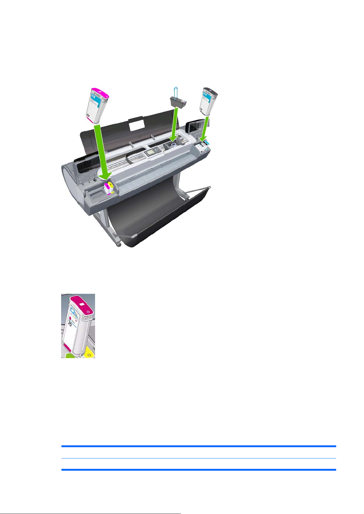
Change an ink cartridge using the following procedure:
1. Scroll to the Ink Menu icon and press OK.
ENWW Ink Cartridge Levels, Information, and Replacement 13
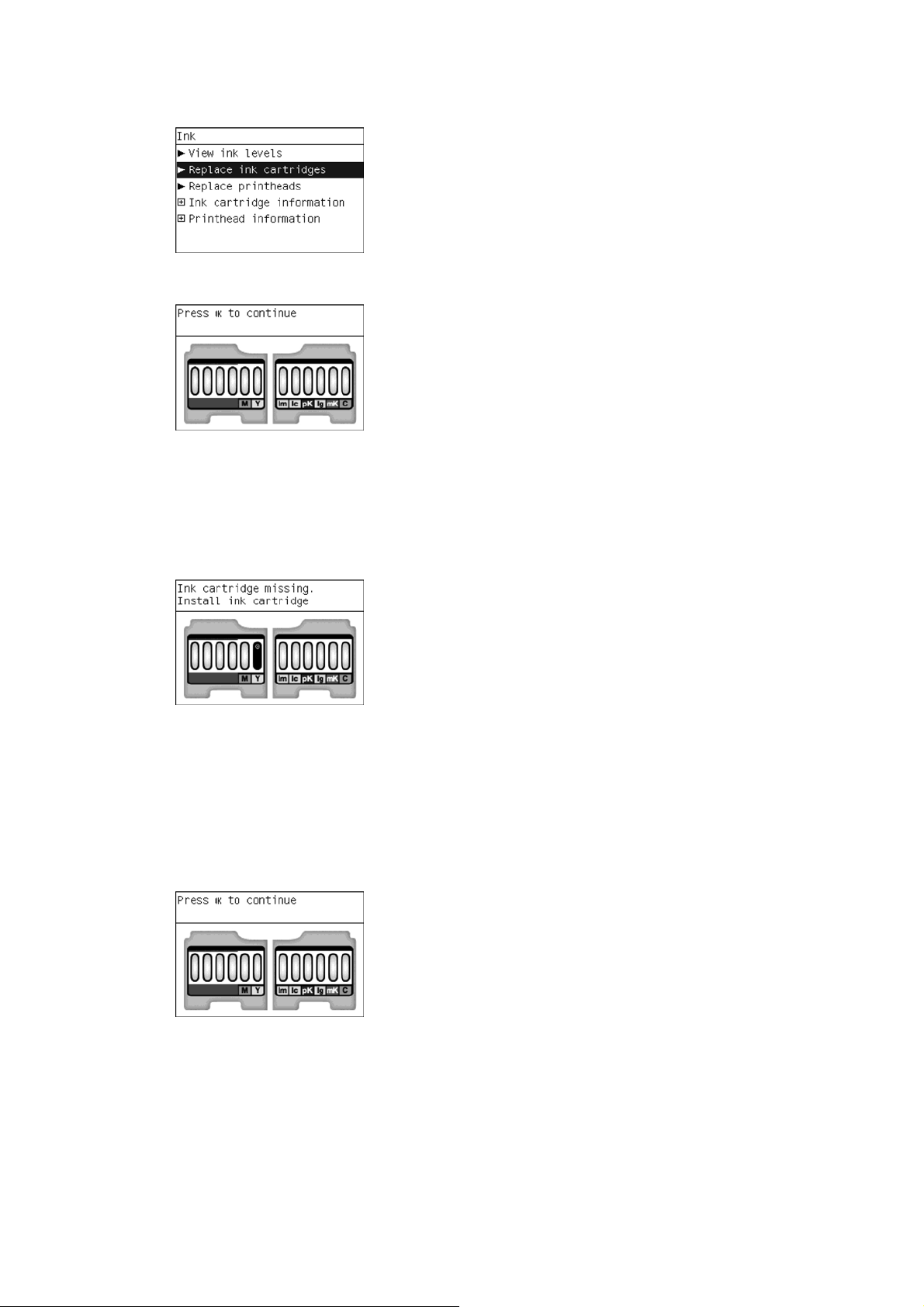
2. In the Ink Menu submenu, scroll to Replace ink cartridges and press OK.
3. The front panel displays the status of the Ink Cartridges.
4. Press OK to continue.
5. Open the relevant Ink Cartridge cover fo r th e Ink Cartridge you want to replace.
6. Pull the required Ink Cartridge straight up to remove it from the printer.
7. The front panel indicates the missing Ink Cartridge.
8. Before removing the cartridge from its wrapping, shake it vigorously.
9. Unwrap the new ink cartridge, find the label identifying the ink color. Check that the letter or letters
marking the empty slot, matches the letter or letters on the cartridge label.
10. Insert the ink cartridge into its slot.
11. Push the cartridge into the slot until it snaps into position. You should hear a beep and see
confirmation that the cartridge has been inserted.
12. When all cartridges have been inserted, close the cover.
14 Chapter 1 Ink Supplies Troubleshooting & Print Quality ENWW
Printhead Information, Replacement and Alignment
Obtaining Printhead Information
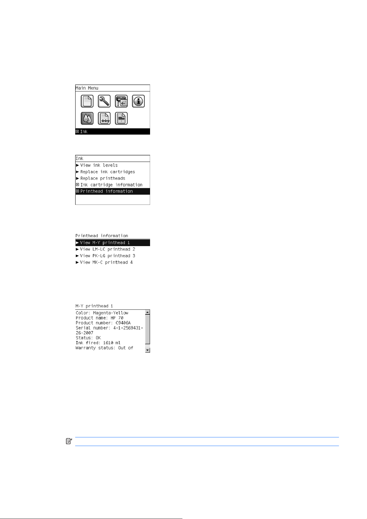
1. Scroll to the Ink Menu icon and press OK.
2. In the Ink Menu submenu, scroll to Printhead information and press OK.
3. In the Printhead Information submenu, scroll to the Printhead that you want information on and
press OK.
4. The front panel displays information on the selected Printhead.
The information supplied is:
●
The make of the printhead.
●
The product number of the Printhea d.
●
The serial number of the Printhead.
●
The current status of the printhead.
●
How much ink has been fired (consumed) by the printhead.
NOTE: It is possible for a printhead to consume more than one Ink Cartridge.
●
The current warranty status of the Printhead.
ENWW Printhead Information, Replacement and Alignment 15
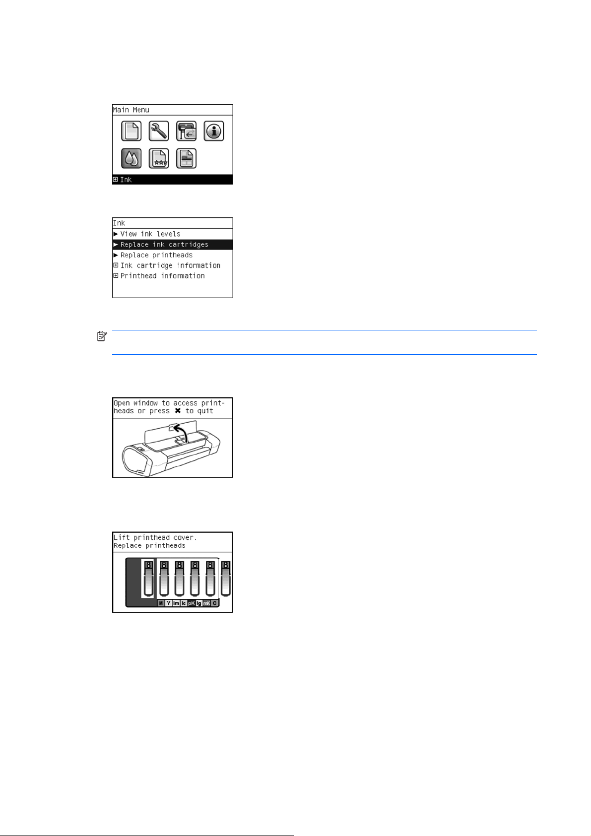
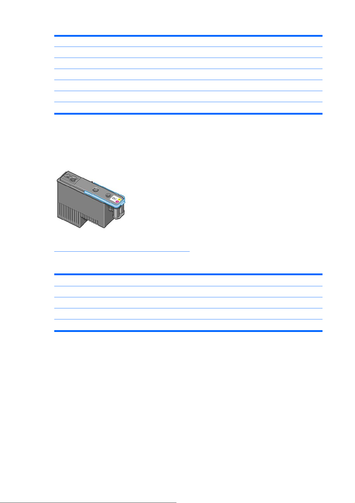
Changing a Printhead
1. Scroll to the Ink Menu icon and press OK.
2. In the Ink Menu submenu, scroll to Replace printheads and pressOK .
3. The printer moves the Carriage to the correct position to replace Printheads.
NOTE: If the carriage is left in the removal position for more than three minutes without inserting
or removing any printheads, it will try to move back to its normal position at the right-hand end.
4. When the carriage has stopped moving, the front panel display will prompt you to open the wi ndow
and lift the carriage cover.
5. Open the window.
6. Lift the Carriage cover to access the printhea d s.
7. Lift the blue handle and pull the Printhead straight up out of the Carriage.
16 Chapter 1 Ink Supplies Troubleshooting & Print Quality ENWW
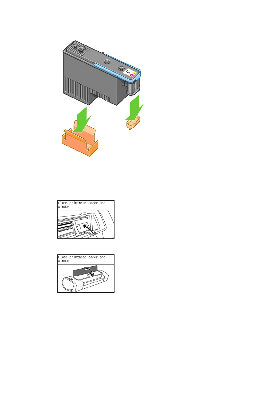
8. To insert a new printhead first remove the or an ge p ro te c tive ca ps.
9. The printhead is designed to prevent you from accidentally inserting it into the wrong slot. Check
that the colored label on the printhead matches the colored label of the carriage slot into which th e
printhead is to be inserted. Insert the printhead slowly and vertically, straight down. It may be
damaged if you insert it too fast, or at an angle, or if you rotate it as you insert it.
10. Insert all other printheads that need to be installed, and close the carriage cover.
11. Close the Window.
12. When all the printheads have been inserted correctly and accepted by the printer, the printer will
beep. If the printer does not beep when you insert the printhead an d the Replace message appears
on the front panel display, the printhead may need to be reinserted.
The front panel display confirms that all printheads are correctly inserted. The printer will start
checking and preparing the printheads. The front panel display confirms that all printheads are
correctly inserted. The printer will start checking and preparing the printheads. The default routine
process, when all printheads are changed, takes 25 minutes. If the printer finds problems in
preparing the printheads, it will take longer, up to 55 minutes. For a single printhead insertion, the
times vary between 15 and 35 minutes. After all printheads are checked and prepared, for the
printhead realignment.
ENWW Printhead Information, Replacement and Alignment 17

Aligning Printheads
Precise alignment between printheads is essential for accurate colors, smooth color transitions, and
sharp edges in graphical elements. Your printer has an automatic printhead alignment process which
runs whenever a printhead has been accessed or replaced.
In cases where the paper has jammed, you have used a custom paper, or are experiencing problems
with color accuracy you may need to align the printheads. If the paper has jammed, it is re commende d
that you reinsert the printheads and initiate the realignment procedure with the Image Quality
Maintenance menu.
NOTE: Do not use transparent and semi-transparent paper to align the printheads. Photo paper is
recommended for the best quality.
Reinsert Printheads Procedure
1. If the realignment process is running and the wrong paper is loaded, press the cancel key on the
front panel. Do not print if the realignment process has been canceled. You can restart the
alignment with the Image Quality Maintenance menu procedure.
2. Load the paper you wish to use. You can use a roll or cut sheet.
3. Remove and reinsert all the printheads, see Remove a printhead and Insert a printhead. This will
start the printhead alignment procedure.
4. Ensure the transparent window closed, as a strong light source near the printer during printhead
realignment can affect alignment.
5. The process will take about six minutes. Wait until the front panel display shows the process
complete before using the printer.
Image Quality Maintenance Procedure
1. Load the paper you wish to use. You can use a rol l or cut sheet, however, it must be at le ast a 16
inches roll, or an A2 portrait sheet (420mm x 594mm). Do not use transparent and semi-transparent
paper to align the printheads. Photo paper is recommended for the best results; plain, bond and
thin coated papers provide acceptable but marginal results.
2. Press the Menu key to return to the main menu and select the Image Quality Maintenance menu
icon.
3. Select Alig n printheads. The printer will check to see if it has en ough paper to run the realignment.
18 Chapter 1 Ink Supplies Troubleshooting & Print Quality ENWW

4. If the loaded paper is satisfactory, the printer will run the realignment and print a realignment
pattern. Ensure the transparent window is closed, as a strong light source near the printer during
printhead realignment can affect alignment.
Figure 1-1 Z5200 Plot:
5. The process will take about eight minutes. Wait until the front panel display shows the process
complete before using the printer.
Scanning errors during alignment
If the alignment process fails, a Scanning problems message appears on the front panel. This means
that the alignment has not completed successfully. Ther efore the printer is not aligned and the alignment
should be repeated before printing with good image quality. The problem may be due to:
●
The paper used was not valid, repeat the alignment with valid paper.
●
Printhead health problems, clean printheads.
●
The alignment was done with the transparent window open, repeat th e alignment with the window
closed.
If the problem persists after using valid paper, cleaning the printheads, a nd keeping the window closed,
there may be a Failure in the scanning system needing reparation or the printheads, although clean,
may not work and need to be replaced.
ENWW Printhead Information, Replacement and Alignment 19

Ink Cartridge and Printhead Status Messages
Ink Cartridge Status Messages
OK The Ink Cartridge is operating correctly and no action is
required.
Missing There is no Ink Cartridge present, or it is not properly
connected to the printer
Low The Low message is an early warning sign and it is advisable
that new supplies should be obtained of that particular color.
The amount of ink remaining in the Ink Cartridge depends on
it’s capacity, but there is approximately 14% of ink available for
the user.
Very Low When theVery Low message is displayed, overnight printing
should not be attempted. Changing the Ink Cartridge is
strongly recommended to prevent the printer from stopping
halfway through a print. There is approximately 8% of ink
available for the user.
Empty The printer will stop and will not be able to continue printing
until a new Ink Cartridge has been installed. If this occurs
halfway through printing an image, you should check the
quality of this image, as stopping mid-plot can affect the print.
It would be recommended to reprint the image once a new Ink
Cartridge has been installed.
Reseat You are recommended to remove the Ink Cartridge and then
reinsert it.
Replace You are recommended to replace the Ink Cartridge with a new
Ink Cartridge.
Altered There is something unexpected about the Ink Cartridge's
status.
Expired The Ink Cartridge has passed the expiration date.
Printhead status messages
OK The Printhead is operating correctly and no action is required.
Missing There is no Printhead present, or it is not properly connected
to the printer.
Test printhead
separately
You are recommended to test the printheads individually to find
the failing printhead. Remove all the printheads and insert
them alone one by one, Closing the latch and the carriage
cover after every insertion. The front panel display will indicate
the failing one showing the reseat or replace message.
Reseat You are recommended to start the printhead removal process
from the front panel, but instead of removing the printhead,
simply press the OK key on the front panel.
Replace You are recommended to remove the printhead and then
reinsert it; if that fails, clean the electrical connections; if that
fails, replace the printhead with a new printhead.
Replacement
incomplete
A printhead replacement process has not completed
successfully, relaunch the replacement process and let it finish
completely (it is not needed to change the printheads).
Remove The printhead is not a suitable type for use in printing (for
instance, a setup printhead).
20 Chapter 1 Ink Supplies Troubleshooting & Print Quality ENWW

Solving Ink Supplies Problems
Most of the problems that you could encounter when working with the ink supplies are solved with
guidance from the front panel. A full list of front panel messages are supplied in the User’s Guide.
You Cannot Insert the Ink Cartridge Into the Printer
1. Ensure that you have the correct hp Ink Cartridge.
2. Ensure that the Ink Cartridge is the correct color for that slot.
3. Ensure that the Ink Cartridge is the correct orientation, with the color coded label at the top.
NOTE: Never clean inside the Ink Cartridge slo ts as this can cause damage to the Printer.
You Cannot Insert the Printhead Into the Printer
1. Ensure that you have the correct hp Printhead.
2. Ensure that the printhead is the correct color for that slot.
3. Ensure that the printhead is in the correct orientation.
4. Ensure that the protective cap is removed from the Printhead.
The front panel says to reset or replace a printhead
1. From the front panel, turn the power off then ON.
2. Check the front panel display message, if it shows the ready message, the printer is ready to print.
If the problem remains continue with the next step.
3. Remove the printhead.
4. Clean the electrical connections on the backside of the printhead with a lint free cloth. You can
carefully use a mild rubbing alcohol if moisture is needed to remove residue. Do not use water.
You can use the Flex Contacts Cleaning Tool.
This is a delicate process and may damage the printh ead. Do not touch the n ozzles on the bottom
side of the printhead, especially not with any alcohol.
ENWW Solving Ink Supplies Problems 21
Loading...