


 Loading...
Galaxy Dimension
Installer Manual
Honeywell Security

|
|
Galaxy Dimension Installer Manual |
Table of Contents |
Contents
INTRODUCTION ....................................................................................... |
1-1 |
Variants ................................................................................................................ |
1-1 |
SECTION 1: QUICK SETUP .................................................................... |
1-3 |
SECTION 2: SYSTEM ARCHTECTURE .................................................. |
2-1 |
PCB Layout .......................................................................................................... |
2-2 |
RS485 Expansion Module (GD-520 only) ......................................................... |
2-3 |
System Installation and Wiring ......................................................................... |
2-4 |
Connecting the Galaxy Dimension to the PSTN.............................................. |
2-5 |
Connecting Additional Telecom Apparatus .......................................................................... |
2-6 |
Line Monitoring .................................................................................................................... |
2-6 |
Stand-by Battery ................................................................................................. |
2-7 |
Battery Start-up ..................................................................................................................... |
2-7 |
On-Board Power Supply Unit............................................................................. |
2-7 |
Memory ................................................................................................................ |
2-8 |
RS485 Data Communication Bus (AB Lines) ................................................... |
2-8 |
RS485 Wiring Configurations ............................................................................ |
2-8 |
RS485 Wiring Recommendations ..................................................................... |
2-9 |
Zones ................................................................................................................. |
2-11 |
Zone Addresses ................................................................................................................ |
2-11 |
Wiring Zones ..................................................................................................................... |
2-13 |
Wiring Multiple Detectors ................................................................................ |
2-15 |
Wiring Keyswitches ............................................................................................................ |
2-15 |
Wiring Terminator Buttons .................................................................................................. |
2-16 |
Outputs .............................................................................................................. |
2-16 |
Output Applications ......................................................................................... |
2-17 |
Trigger Header .................................................................................................. |
2-18 |
Trig 1-6 ............................................................................................................................... |
2-18 |
Supply ................................................................................................................................ |
2-18 |
SPI Header ......................................................................................................... |
2-19 |
SECTION 3: PERIPHERALS ................................................................... |
3-1 |
General................................................................................................................. |
3-1 |
Wiring ................................................................................................................... |
3-1 |
i

Table of Contents
Galaxy Dimension Installer Manual
Configuring ......................................................................................................... |
3-1 |
Addressing........................................................................................................................... |
3-1 |
Connecting the RIO .............................................................................................................. |
3-2 |
Configuring the RIO .............................................................................................................. |
3-2 |
RIO Outputs .......................................................................................................................... |
3-3 |
RF RIO .................................................................................................................. |
3-4 |
Connecting the RF RIO ........................................................................................................ |
3-4 |
Addressing the RF RIO ........................................................................................................ |
3-5 |
RF RIO Programming .......................................................................................................... |
3-6 |
Configuring the RF RIO ........................................................................................................ |
3-6 |
Power Supply Unit .............................................................................................. |
3-7 |
Configuration ........................................................................................................................ |
3-7 |
Installation Instructions ......................................................................................................... |
3-8 |
Battery .................................................................................................................................. |
3-9 |
Battery Test ........................................................................................................................... |
3-9 |
Specifications ....................................................................................................................... |
3-9 |
EN50131 Compliance ......................................................................................................... |
3-9 |
Printer Interface Module .................................................................................. |
3-10 |
ISDN Module ...................................................................................................... |
3-11 |
Programming the ISDN Module ......................................................................................... |
3-11 |
Ethernet Module ............................................................................................... |
3-12 |
Configuring the Ethernet Module ....................................................................................... |
3-12 |
Ethernet Communication ................................................................................................... |
3-12 |
Galaxy Dimension and 2-Way Audio .............................................................. |
3-13 |
Introduction......................................................................................................................... |
3-13 |
Audio Interface Module ...................................................................................................... |
3-13 |
MUX Module ...................................................................................................................... |
3-15 |
Remote Servicing Suite.................................................................................... |
3-17 |
User Management Suite ................................................................................... |
3-17 |
SECTION 4: KEYPADS ........................................................................... |
4-1 |
The Galaxy Mk7 Keypad/KeyProx..................................................................... |
4-1 |
General ................................................................................................................................ |
4-1 |
Power Consumption ............................................................................................................ |
4-1 |
Wiring the Keypad/KeyProx ................................................................................................. |
4-2 |
Keypad/KeyProx Installation Procedure............................................................................... |
4-2 |
Self Diagnostics.................................................................................................................... |
4-5 |
Keypad/KeyProx Operation ................................................................................................. |
4-5 |
The Galaxy KeyProx ........................................................................................... |
4-8 |
General ................................................................................................................................ |
4-8 |
Addressing........................................................................................................................... |
4-8 |
ii
|
|
Galaxy Dimension Installer Manual |
Table of Contents |
Operation ............................................................................................................................. |
4-8 |
Card Types........................................................................................................................... |
4-8 |
The Galaxy Dimension TouchCenter................................................................ |
4-9 |
General ................................................................................................................................ |
4-9 |
TouchCenter Installation Procedure ..................................................................................... |
4-9 |
Configuring a TouchCenter ................................................................................................ |
4-10 |
Set-up Menu ...................................................................................................................... |
4-10 |
TouchCenter - Operation ................................................................................................... |
4-11 |
Specifications ..................................................................................................................... |
4-11 |
SECTION 5: ACCESS CONTROL ........................................................... |
5-1 |
Group Based Access Control ............................................................................ |
5-1 |
User and Access Templates .............................................................................. |
5-1 |
Time Schedules .................................................................................................. |
5-1 |
Door Control Module .......................................................................................... |
5-2 |
MAX3 .................................................................................................................... |
5-7 |
SECTION 6: SYSTEM OPERATION ........................................................ |
6-1 |
Menu Options...................................................................................................... |
6-1 |
General ................................................................................................................................ |
6-1 |
The Full Menu ...................................................................................................................... |
6-1 |
The Quick Menu .................................................................................................................. |
6-1 |
Menu Access ....................................................................................................................... |
6-1 |
Engineer Mode .................................................................................................................... |
6-2 |
Setting Options ................................................................................................... |
6-5 |
Setting the System Using a PIN ............................................................................................ |
6-5 |
Cancelling the Setting .......................................................................................................... |
6-5 |
Unsetting the System Using a PIN ........................................................................................ |
6-6 |
Engineer Unsetting .............................................................................................................. |
6-6 |
Keyswitch Setting Options .................................................................................................... |
6-6 |
Setting the System with Cards/Tags/Fobs ............................................................................ |
6-6 |
Cancelling and Resetting Alarms and Alerts ........................................................................ |
6-7 |
Recording of Events ............................................................................................................. |
6-7 |
Overriding of Faults and Tampers ........................................................................................ |
6-8 |
Setting Features ................................................................................................................... |
6-8 |
Menu Options 11-19 ......................................................................................... |
6-11 |
Option 11 – Omit Zones (Quick Menu Option 0) .............................................................. |
6-11 |
Option 12 – Timed Set ....................................................................................................... |
6-13 |
Option 13 – Part Set ........................................................................................................... |
6-13 |
Option 14 – Forced Set (Quick Menu Option 1) ................................................................ |
6-13 |
Option 15 – Chime (Quick Menu Option 2) ....................................................................... |
6-13 |
iii

Table of Contents
Galaxy Dimension Installer Manual
Option 16 – Instant Set ....................................................................................................... |
6-13 |
Option 17 – Silent Part ....................................................................................................... |
6-14 |
Option 18 – Home Set ....................................................................................................... |
6-14 |
Option 19 – All Set .............................................................................................................. |
6-14 |
Display Options ................................................................................................ |
6-15 |
Option 21 – Display Zones (Quick Menu Option 3) ........................................................... |
6-15 |
Option 22 – Display Log (Quick Menu Option 4) ............................................................... |
6-16 |
Option 23 – System ............................................................................................................ |
6-17 |
Option 24 – Print (Quick Menu Option 5) ........................................................................... |
6-18 |
Option 25 – Access Doors ................................................................................................. |
6-19 |
Test Options ...................................................................................................... |
6-23 |
Option 31 – Walk Test (Quick Menu Option 6) ................................................................... |
6-23 |
Option 32 – Outputs ........................................................................................................... |
6-25 |
Modify Options ................................................................................................. |
6-26 |
Option 41 – Time/Date (Quick Menu Option 7) ................................................................. |
6-26 |
Option 42 – Codes (Quick Menu Option 8) ....................................................................... |
6-27 |
Option 43 – Summer (Quick Menu Option 9) .................................................................... |
6-38 |
Option 44 – Trace .............................................................................................................. |
6-38 |
Option 45 – Timer Control .................................................................................................. |
6-39 |
Option 46 – Group Omit ..................................................................................................... |
6-43 |
Option 47 – Remote Access .............................................................................................. |
6-44 |
Option 48 – Engineer access ............................................................................................ |
6-50 |
Engineer 1 ......................................................................................................... |
6-51 |
Option 51 – Parameters ..................................................................................................... |
6-51 |
Option 52 – Program Zones .............................................................................................. |
6-71 |
Option 53 – Program Outputs ............................................................................................ |
6-87 |
Option 54 – Links ............................................................................................................. |
6-104 |
Option 55 – Soak ............................................................................................................. |
6-107 |
Option 56 – Communications .......................................................................................... |
6-108 |
Option 57 – System Print .................................................................................................. |
6-151 |
Option 58 – Keypad ......................................................................................................... |
6-152 |
Option 59 – Quick Menu .................................................................................................. |
6-155 |
Engineer 2 ....................................................................................................... |
6-156 |
Option 61 – Diagnostics ................................................................................................... |
6-156 |
Option 62 – Full Test ........................................................................................................ |
6-159 |
Option 63 – Options ......................................................................................................... |
6-160 |
Option 64 – Assemble Zone ............................................................................................ |
6-164 |
Option 65 – Timers .......................................................................................................... |
6-168 |
Option 66 – Pre-checks ................................................................................................... |
6-175 |
Option 67 – Remote Reset .............................................................................................. |
6-176 |
Option 68 – Menu Access ............................................................................................... |
6-177 |
Option 69 – Integrated Access Control ............................................................................ |
6-178 |
iv
|
|
Galaxy Dimension Installer Manual |
Table of Contents |
|
|
Engineer 3 ....................................................................................................... |
6-192 |
Option 71 – SPI Key ......................................................................................................... |
6-192 |
Appendix A: Library .............................................................................. |
A-1 |
Appendix B: SIA and Contact ID Event Codes .................................... |
B-1 |
Appendix C: SIA Event Structure ........................................................ |
C-1 |
Appendix D: Event Log Messages ....................................................... |
D-1 |
Appendix E: Site Data Storage .............................................................. |
E-1 |
Preparing for Storage Mode .............................................................................. |
E-1 |
Enabling Storage Mode ..................................................................................... |
E-1 |
Using Storage Mode ........................................................................................... |
E-2 |
Leaving Storage Mode ....................................................................................... |
E-2 |
Appendix F: Specifications ................................................................... |
F-1 |
Panel Specifications........................................................................................... |
F-1 |
Appendix G: Declaration of Conformity .............................................. |
G-1 |
Compliance and Approvals .............................................................................. |
G-1 |
EN50131 Compliance......................................................................................... |
G-2 |
PD6662 Compliance........................................................................................... |
G-2 |
Public Switched Telephone Network (PSTN) approval.................................. |
G-2 |
Appendix H: Parts List Index................................................................ |
H-1 |
Index .................................................................................................. |
Index-1 |
v

Table of Contents
Galaxy Dimension Installer Manual
vi
Galaxy Dimension Installer Manual |
Introduction |
|
|
INTRODUCTION
This manual gives full instructions required to install and program a Galaxy Dimension control panel and associated peripherals.
Variants
The Galaxy Dimension is available in four variants: GD48, GD-96, GD-264 and GD-520. The differences between each variant are shown in the following table:
|
|
|
|
|
|
Features |
GD-48 |
GD-96 |
GD-264 |
GD-520 |
|
Zones |
16-48 |
16-96 |
16-264 |
16-520 |
|
|
|
|
|
|
|
Outputs (400mA) |
8-24 |
8-48 |
8-132 |
8-260 |
|
Trigger Outputs on Flying Lead |
6 |
6 |
6 |
6 |
|
(100mA) |
|
|
|
|
|
PSU |
2.5A |
2.5A |
2.5A |
2.5A |
|
|
|
|
|
|
|
RS485 Databuses |
1 |
2 |
2 |
4 |
|
Telecom onboard |
Yes |
Yes |
Yes |
Yes |
|
RS232 Interface for online PC |
RS232 |
RS232 |
RS232 |
RS232 |
|
Printer Interface |
RS232 |
RS232 |
RS232 |
RS232 |
|
|
|
|
|
|
|
Ethernet option |
Yes |
Yes |
Yes |
Yes |
|
GPRS option |
3rd Party |
3rd Party |
3rd Party |
3rd Party |
|
Groups |
8 |
16 |
32 |
32 |
|
|
|
|
|
|
|
Keypads |
8 |
16 |
16 |
32 |
|
Keyprox |
3 |
7 |
7 |
24 |
|
Multi-user |
Yes |
Yes |
Yes |
Yes |
|
|
|
|
|
|
|
DCM's with 2 x wiegand |
4 |
16 |
16 |
32 |
|
interfaces |
|||||
|
|
|
|
||
DCM Controlled doors |
8 |
32 |
32 |
64 |
|
Bus mounted prox readers |
4 |
16 |
16 |
32 |
|
(MAX) |
|||||
|
|
|
|
||
Access control groups (user |
50 |
50 |
100 |
100 |
|
templates) |
|||||
|
|
|
|
||
Weekly Timer Schedules |
19 |
35 |
67 |
67 |
|
Annual Holiday Schedules |
16 |
32 |
32 |
32 |
|
Users |
100 |
250 |
999 |
999 |
|
|
|
|
|
|
|
Links |
64 |
128 |
256 |
256 |
|
Remote software update |
Yes |
Yes |
Yes |
Yes |
|
Upload/Download |
Yes |
Yes |
Yes |
Yes |
|
Remote service |
Yes |
Yes |
Yes |
Yes |
|
|
|
|
|
|
|
Network downloader |
Yes |
Yes |
Yes |
Yes |
|
Alarm monitoring |
Yes |
Yes |
Yes |
Yes |
|
Graphics mimic |
Yes |
Yes |
Yes |
Yes |
|
|
|
|
|
|
|
TouchCenter |
1 |
2 |
2 |
4 |
|
Mimic panel |
Yes |
Yes |
Yes |
Yes |
|
|
|
|
|
|
|
Wireless |
Ademco 5800 |
Ademco 5800 |
Ademco 5800 |
Ademco 5800 |
|
Audio Verification Channels |
8 |
16 |
32 |
32 |
|
|
|
|
|
|
|
SMS |
Yes |
Yes |
Yes |
Yes |
Table 1-1. Galaxy Dimension General Specification
1-1

Galaxy Dimension Installer Manual
1-2
Galaxy Dimension Installer Manual |
Quick Setup |
|
|
SECTION 1: QUICK SETUP
To quickly set up a Galaxy Dimension control panel for programming follow these simple steps:
1.Connect a 1k Ω(1%) resistor across each of the zones on the panel and any RIO’s (if connected).
2.Ensure that the tamper return loop — the terminals marked as AUX TAMP/GND on the PCB — is a complete loop.
3.Connect a keypad to the AB LINE terminals on the control panel.
|
|
|
Control Panel |
Keypad |
|
(Line 1) |
||
|
||
B1 |
B |
|
|
|
|
A1 |
A |
|
|
|
|
- |
- |
+12V +
Table 1-2. Terminal Connections
4.Connect a 680 ΩEnd Of Line (EOL) resistor across the A and B terminals of the keypad.
5.Ensure that the keypad is fitted to the wall (see Keypad Installation Procedure, Section 4).
6.Connect the battery before replacing the control panel lid.
7.Connect the mains wiring to the control panel. Do not switch the mains ON.
8.Replace the control panel lid and secure the fastening screws.
9.Switch on the mains voltage (230 Va.c. / 50 Hz).
10.The following sequence of events occur:
• the keypad buzzer and control panel horn (if fitted) activate for 10 - 20 seconds,
•flashing is displayed on the keypad,
•the sounders stop and the keypad displays become blank,
•the green power LED lights and the following displays on the keypad
|
|
Configuring |
|
||
|
|
Please |
Wait |
|
|
|
|
|
|||
• the default banner is then displayed on the keypad. |
|
||||
|
|
|
|
|
|
|
|
GALAXY |
<XXX> |
<VY.YY> |
|
|
|
01:01 |
SUN 01 JAN |
|
|
|
|
|
|
|
|
where: |
XXX is the panel type |
|
|
|
|
|
Y.YYis the panel software revision |
|
|||
11. The system is now ready to be programmed. Refer to Section 6 System Operation for programmingdetails.
12. Default User code is 12345 Default Engineer code is 112233
1-3

Galaxy Dimension Installer Manual
1-4
Galaxy Dimension Installer Manual |
Configuration |
|
|
SECTION 2: SYSTEM ARCHTECTURE
16 zones on board
PSTN (comm 1) |
on board |
Galaxy |
|
||||
|
8 outputs |
||||||
|
telecom |
||||||
|
|
|
|
||||
|
area |
|
Trigger |
|
on board |
||
|
|
|
Header |
|
plus 6 outputs |
||
|
Line |
|
Line |
|
Line |
Line |
on trigger header |
Audio Interface |
|
|
|
||||
Module (1) |
1 |
|
2 |
|
3 |
4 |
|
RS232 |
|
|
|
|
|
|
|
Serial Port |
|
|
|
|
|
|
Lines 2, 3 and 4 have |
(comm 6) |
|
|
|
|
|
|
the same configuration |
RS485 line |
|
|
|
|
|
|
|
|
Cable run 1 km (max) |
|
|||||
* NOTE: |
|
*Keypads |
|
|
|
||
Valid addresses for the |
|
|
|
|
|||
keyprox are: |
|
CP027/ |
|
|
|
|
|
Line 1 (0, 1 & 2). |
|
Keyprox |
|
|
|
|
|
Line 2 (0, 1, 2, & 3 ). |
|
CP028 |
|
|
|
Touch |
|
This sets the address for both |
|
|
|
|
|
|
Center |
the keypad and card reader |
|
|
|
|
|
|
CP040 |
parts of the keyprox. |
|
|
|
|
|
|
|
* Certain keypad and |
|
|
|
|
|
|
|
max addresses can |
|
|
4 outputs |
|
|
||
be replaced by a |
RIO |
|
|
|
|
|
|
combined keyprox unit. |
|
|
|
|
|
||
|
C072 |
|
|
|
|
|
|
NOTE: |
|
|
8 zones |
|
|
||
RIOs, RF RIO's and |
|
|
|
|
|||
OR |
|
|
|
|
|
||
PSU's can be mixed on |
4 outputs |
|
|
||||
|
|
|
*Max |
||||
the lines. |
|
|
|
|
|
|
|
Smart PSU |
|
|
|
|
|
MX03 |
|
P015 |
|
|
|
|
|
|
OR |
|
|
|
8 zones |
|
|||
|
OR |
|
|
||||
|
|
|
|
|
|
||
|
4 outputs |
|
|
|
DCM |
||
Power Unit P025 |
|
|
|
|
|
C080/81 |
|
|
|
|
|
|
|
||
or |
|
|
|
|
|
|
|
Power RIO P026 |
|
|
|
|
|
|
|
|
8 zones |
|
|
|
|
||
|
OR |
|
|
|
|
|
|
|
RF RIO Module |
|
|
||||
|
C076 |
|
|
|
|
|
|
NOTE: |
|
|
|
|
|
|
|
The Telecom, Printer Interface, |
|
Telecom Module |
|
|
|||
RS232, Ethernet and ISDN |
|
|
|
||||
|
E062 (comm 5) |
|
|
||||
modules can only be |
|
|
|
|
|
|
|
connected to line 1. |
|
|
|
|
|
|
|
If a Telecom module is attached, |
|
|
|
|
|
|
|
keypad address E cannot be |
RS232 Module |
|
|
||||
connected to line 1(address E is |
|
|
|||||
E054 (comm 2) |
|
|
|||||
shown as 18 on the system). |
|
|
|||||
|
|
|
|
|
|
|
|
If an RS232 module is attached, |
|
|
|
|
|
|
|
keypad address D cannot be |
|
|
|
|
|
|
|
connected to line 1 (address D is |
|
|
|
|
|
|
|
shown as 17 on the system). |
ISDN Module |
|
|
||||
If an Ethernet module is attached, |
E077 (comm 3) |
|
|
||||
keypad address B cannot be |
|
|
|
|
|
|
Twisted Pair |
connected to line 1 (address B is |
|
|
|
|
|
|
|
|
|
|
|
|
|
Screened Cable |
|
shown as 15 on the system). |
|
|
|
|
|
|
|
|
|
|
|
|
|
|
|
If an ISDN module is attached, |
Ethernet Module |
|
|
||||
keypad address C cannot be |
|
|
|||||
E080 (comm 4) |
|
|
|||||
connected to line 1 (address C is |
|
|
|||||
|
|
|
|
|
|
|
|
shown as 16 on the system). |
|
|
|
|
|
|
|
|
Printer Interface |
|
|
|
|||
|
A134/A161 |
|
|
|
|
||
*Keypads CP027/ Keyprox CP028
Touch
Center
CP040
*Max MX03
OR
DCM
C080/81
4 outputs
RIO
C072
8 zones
OR
4 outputs
Smart PSU


 P015
P015
8 zones
OR
4 outputs
Power Unit P025
or
Power RIO P026
8 zones
OR
RF RIO Module
C076
|
GD-48 |
GD-96 |
GD-264 |
GD-520 |
|
|
|
|
|
Lines |
1 |
2 |
2 |
4 |
|
|
|
|
|
Keypads |
8 |
8 per line |
8 per line |
8 per line |
|
|
|
|
|
Keyproxes |
3 |
3 (line 1) |
3 (line 1) |
3 (line 1) |
|
|
4 (line 2) |
4 (line 2) |
7 (lines 2, 3, 4) |
Touch Center |
1 |
1 per line |
1 per line |
1 per line |
|
|
|
|
|
MAX's |
4 |
8 per line |
8 per line |
8 per line |
|
|
|
|
|
DCM's |
4 |
8 per line |
8 per line |
8 per line |
|
|
|
|
|
RIO's/PSU's |
4 |
4 (line 1) |
15 (line 1) |
15 (line 1) |
|
|
6 (line 2) |
16 (line 2) |
16 (lines 2, 3, 4) |
Figure 2-1. Galaxy Dimension System Configuration
2-1

Layout PCB .2-2 Figure 2-2
Telecom
Connect
RS485 line 1
RS485 line 2
RS232 Port
|
|
|
|
|
|
|
|
|
|
|
|
|
|
|
SPI |
|
|
|
Telecom |
Debug |
Memory |
Expansion card |
|
|
|
|
|
|
|
|
|
Program |
|
|
|
|
|
|
|
|
|
|
|
|
Header |
|
||||
|
|
interface |
|
|
|
|
|
|
|
|
|
|
||||
|
|
Socket |
Header |
backup |
|
|
|
|
|
|
|
|
|
|
|
|
|
|
|
|
|
|
|
|
|
|
|
|
|
|
|||
|
|
|
|
battery |
|
|
|
|
|
|
|
|
|
|
|
|
|
|
SKT2 |
|
|
|
|
|
|
|
|
|
|
|
|
|
|
B |
LINE |
|
|
|
|
|
|
|
|
|
|
|
|
|
|
|
A |
PHONE |
|
|
|
PROCESSOR |
|
|
|
|
|
|
OFFWALL |
TAMPER |
|
|
|
A B |
|
|
|
|
|
|
|
|
|
LK2 |
|
Jumper Lead |
||||
|
|
|
|
|
MICRO |
|
|
|
|
|
|
|
|
|
|
for off-wall |
|
|
|
|
|
|
|
|
|
|
|
|
|
|
|
|
|
|
|
|
|
|
|
|
|
|
|
|
|
BATTERY |
|
|
|
tamper switch |
B1 |
|
|
|
|
|
|
|
|
|
|
|
|
|
|
|
|
|
|
|
Trigger |
|
|
|
|
|
|
|
START UP |
|
|
|
|
|
|
|
|
|
|
|
|
|
|
|
|
|
|
|
|
||
A1 |
|
LK3 RS485 line 2, 680 termination |
RAM1 |
|
|
|
|
|
|
LK4 |
|
|
|
|
||
|
|
|
Header |
|
|
|
|
|
|
|
|
|
|
|||
|
Engineer socket |
|
|
|
|
|
|
|
|
|
|
|
|
|||
GND |
|
|
|
|
|
|
|
|
|
|
|
|
|
|
||
+12V |
(RS485 Line1) |
|
|
|
|
|
|
|
|
|
|
|
|
|
|
|
LK5 RS485 line 1, 680 termination |
|
|
|
|
|
|
|
|
|
|
|
|
|
|||
|
|
|
|
|
|
|
|
|
|
Horn output |
|
|
|
|
||
B2 |
|
|
|
|
|
|
|
|
|
|
|
|
|
|
|
|
|
|
|
|
FLASH |
|
|
|
|
|
|
volume control |
|
|
|
||
A2 |
|
|
|
|
|
|
|
|
|
|
|
|
|
|||
|
LED1(for Telecoms) |
|
|
Pull-up switches |
|
|
|
BATT |
AC |
Leads for |
||||||
GND |
|
|
|
|
|
|||||||||||
|
|
|
|
|
|
|
|
|
|
|
|
|
|
|
||
+12V |
LED2 (for RS232) |
|
|
|
|
|
|
|
|
|
AUX3 |
|
|
|
lid tamper |
|
|
AUX2 |
SW3 |
1 |
2 |
3 |
4 5 |
6 7 8 |
SWITCH |
F2 |
|
F1 |
LID TAMP |
||||
TX |
(RS485 Line 2) |
|
|
|||||||||||||
|
|
Engineer socket |
|
|
ON |
|
|
|
|
RIO |
|
|
|
|
microswitch |
|
|
|
|
|
|
|
|
|
|
|
|
|
|
||||
|
|
|
|
|
|
|
|
|
|
|
|
|
|
|
|
|
RX |
AUX1 |
|
|
|
|
|
|
|
|
|
|
|
|
-BAT |
|
|
CTS |
F4 |
|
F3 |
|
|
|
|
|
|
|
|
|
|
+BAT |
Battery |
|
RTS |
RS232 Port socket |
|
|
|
|
|
|
|
|
|
|
|
|
14.5 |
terminals |
|
|
|
|
|
|
|
|
|
|
|
|
N/O C N/C |
|
|
|
|
|
|
|
|
|
|
|
+12V |
|
+12V |
|
|
+12V |
|
+12V |
1 |
2 |
3 |
4 |
+12V |
1 |
2 |
3 |
4 |
AUX |
G |
1 0V 2 |
3 0V 4 |
5 0V 6 |
1 0V 2 |
3 0V 4 |
5 0V 6 |
TAMP |
N |
|||||||||||||
RIO 0 |
7 0V 8 |
RIO 1 |
7 0V 8 |
|
RIO 0 |
|
|
|
RIO |
1 |
|
D |
NOTE: |
Fuse AUX1 controls |
|
RS485 line 1, RIO 0 (zones 1-8) |
|
Fuse AUX2 controls |
|
RS485 line 2, RIO 1 (zones 1-8) |
|
Fuse AUX3 controls an independent |
|
12V output which can be used for a |
|
communicator or screw. |
|
|
|
|
|
|
|
|
|
|
|
|
|
|
|
|
|
|
|
|
|
|
|
|
|
|
|
|
|
16 on-board zones |
|
|
Relay |
|
|
External |
||||||
|
|
|
AUX3 |
||||||||||
|
|
|
loudspeaker |
||||||||||
|
|
|
|
|
|
|
Output |
|
|
||||
NOTE: |
Zones 1-8 |
(RIO 0 line 1) |
|
|
|
|
|
||||||
|
|
|
|
|
|
|
|
||||||
|
Zones 1-8 |
(RIO 1 line 1 |
(switch SW3-8 |
OFF)) |
|
|
|
|
|||||
|
|
|
|
|
OR |
|
|
|
|
|
|
|
|
|
Zones 1-8 |
(RIO 1 line 0 |
(switch SW3-8 |
ON)) |
|
|
|
|
|||||
Layout PCB
Layout PCB
Manual Installer Dimension Galaxy
Galaxy Dimension Installer Manual |
RS485 Expansion Module |
|
|
The 7 transistorised outputs on the Galaxy Dimension can be configured to open collectors by setting the dip switch SW3 to the OFF position.
NOTE: Output 2 on RIO 0 (relay output) is not affected.This is a form C relay that can switch up to 1 amp at 24 volts DC.
The following table shows which outputs are controlled by which switches.
(SW3) |
RIO |
Output |
|
|
|
1 |
0 |
1 |
|
|
|
2 |
0 |
3 |
|
|
|
3 |
0 |
4 |
|
|
|
4 |
1 |
1 |
|
|
|
5 |
1 |
2 |
|
|
|
6 |
1 |
3 |
|
|
|
7 |
1 |
4 |
|
|
|
Table 2-1. SW3 Transistorised Outputs Control
RS485 Expansion Module (GD-520 only)
The RS485 Expansion Module is attached to the GD-520 to give 2 extra RS485 (AB) lines.
This module can also be added to a GD-264 to convert it into a GD-520. Jumpers LK1 and LK2 can be removed to disable the on-board end-of-line resistors.
SKT2
B |
LINE |
A |
PHONE |
A B |
B1 |
RS485 |
|
A1 |
EXPANSION |
|
GND |
MODULE |
|
+12V |
||
|
||
B2 |
|
|
A2 |
Jumpers |
|
GND |
||
|
||
+12V |
|
AC
TX
RX
CTS RTS
LK1 |
LK2 |
Twin |
|
RS485 |
|
lines |
A3 B3 A4 B4 |
1 |
2 |
3 |
4 |
5 |
6 |
7 |
8 |
F1 |
LID TAMP |
ON |
|
|
|
|
|
|
|
|
|
-BAT
+BAT
14.5
N/O C N/C
|
|
|
|
|
|
|
|
|
|
|
|
|
|
|
|
|
|
|
|
|
|
|
|
|
|
|
|
|
|
|
|
|
|
|
|
|
|
|
|
|
|
|
|
|
|
|
|
|
|
|
|
|
|
|
|
|
|
|
|
|
|
|
|
|
|
|
|
|
|
|
|
|
|
|
|
|
|
|
|
|
|
|
|
|
|
|
|
|
|
|
|
|
|
|
|
|
|
|
|
|
|
|
|
|
|
|
|
1 |
|
|
|
|
|
|
|
|
|
|
|
|
|
|
|
|
|
|
|
|
|
|
|
|
|
|
|
|
|
|
|
|
|
|
|
|
|
|
|
|
|
|
|
|
|
|
|
|
|
|
|
|
|
|
|
|
|
|
|
|
|
|
|
|
|
|
1 |
0V 2 |
|
|
3 |
|
0V 4 |
+12V |
5 |
0V 6 |
|
7 |
0V 8 |
+12V |
|
1 |
0V 2 |
|
|
3 |
0V 4 |
+12V |
5 |
0V 6 |
|
7 |
|
0V 8 |
+12V |
|
|
|
2 |
|
3 |
4 |
|||||||||||||||||||||
|
|
|
|
RIO 0 |
|
|
|
|
|
RIO 1 |
|
|
|
|
|
|
|
|
|
RIO 0 |
|
||||||||||||||||||||||||||||||||||||
+12V
|
|
|
|
|
|
|
|
|
|
|
|
|
|
1 |
2 |
|
3 |
4 |
|
|
|
RIO 1 |
|
|
|
||
AUX G
 TAMP DN
Figure 2-3. RS485 Expansion Module
2-3
Installation Recommendations |
Galaxy Dimension Installer Manual |
|
|
System Installation and Wiring
The installation and wiring must be performed by a competent engineer. For permanently connected equipment, a readily accessible disconnect device must be incorporated in the fixed wiring. The Galaxy Dimension control panel must be connected to the a.c. mains supply (230/240 Va.c. 50 Hz) via a fused connection outlet in accordance with EN60950-1: 2001
The fuse in the mains outlet must not exceed 3A.
WARNING: A means of isolation from the mains supply must be provided within 2 metres of the control panel. Where live and neutral supplies can be identified, a fused spur with a 3 amp fuse, must be fitted on the live circuit. Where live and neutral circuits cannot be reliably identified, 3 amp fuses must be fitted to both circuits.
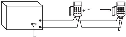
Route the mains cable through the hole on the right hand side of the enclosure base. Securely anchor the cable to the box using the tie-wrap as shown in the following Figure:
|
Keyhole |
AC connect |
|
|
|
|
slot (top) |
|
PCB |
|
Mains |
|
transformer |
|
|
|
|
|
|
Earth wire |
|
|
Terminal |
|
|
block |
Enclosure |
|
Mains cable |
base |
|
Tie wrap
Attaching hole |
Attaching hole |
Figure 2-4. Securing the Mains Cable to the Enclosure Base
Secure the panel base to the wall using three 1.5" No. 8 round head steel screws through the holes provided.
The mains cable used must be a three core type (with green/yellow earth insulation) of adequate current carrying capacity.
Connect the mains cable to the mains terminal block as follows:
•blue wire to the terminal marked N (Neutral)
•green/yellow wire to the terminal marked (Earth)
•brown wire to the terminal marked L (Live)
NOTE: No other connections to the mains connector are permitted.
All wiring must be in accordance with local regulations and the installation must conform to EN60950.
2-4
Galaxy Dimension Installer Manual |
System Wiring |
|
|
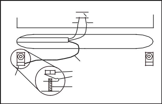
Connecting the Galaxy Dimension to the PSTN
The Telecommunications Network Voltage (TNV) port (terminalsAand B on PCB) must be permanently connected (hard-wired) to the PSTN via a master socket, refer to Figure 2-5.
Telecom
Socket
RJ11
Plug
LINE PHONE
Master socket |
B A B A |
Secondary socket |
Incoming |
line 2 |
line 1 |
PSTN Line |
line 1 |
line 2 |
|
Figure 2-5. Connecting the Galaxy Dimension to the PSTN
NOTES: 1. Terminals 1 and 2 on the Master Socket must be hard-wired to LINE Aand B terminals on the Galaxy Dimension PCB. The connection is polarity independent.
2.It is strongly recommended that the Galaxy Dimension panel is the only device on the line.
3.If another device is to be connected to the line, connect the PHONE terminals on the PCB to terminals 1 and 2 on a Secondary socket.
There are two methods of connecting the on-board Telecom Module to the PSTN:
Method 1
Using cable suitable for connection to 2.8 mm diameter screw terminals, strip back approximately 20 mm of the outer sheath and then remove approximately 4 mm of the insulation from the wires to be connected to the Galaxy Dimension PCB.
Connect terminals 1 and 2 on the Master socket across the LINEAand B terminals on the Galaxy Dimension PCB, see Figure 2-5.
Method 2
Use a standard cable with RJ11 plug on one end and plug into the telecom socket on the Galaxy Dimension PCB. Connect the other end of the cable to the Master socket as described in Method 1.
NOTE: Digital Subscriber Line (DSL) should not be used. If it is used, connect a suitable filter to the phone line.
2-5
System Wiring (cont’d) |
Galaxy Dimension Installer Manual |
|
|
Connecting Additional Telecom Apparatus
A secondary socket, allows additional telecom apparatus to be connected in series with the on-board telecom module. Connect the PHONE terminalsAand B on the PCB to the terminals on the secondary socket. See Figure 2-5.
Line Monitoring
Under normal idle state conditions, the on-board Telecom Module monitors the PSTN line. The communication status is indicated by the state of the red LED (LED1) as shown in the following table:
|
|
|
LED STATE |
INDICATION |
|
|
|
|
LED OFF |
No d.c. supply |
|
|
|
|
ON - 01s, OFF - 0.9s |
Normal Communication |
|
|
|
|
Single pulse at end of call |
Normal Communication |
|
|
|
|
Flashing at end of alarm call |
Failed Communication |
|
|
|
|
On during alarm monitoring, |
Normal Communication |
|
Remote Servicing and SMS |
||
|
||
Flickering during alarm monitoring, |
Poor Communication |
|
Remote servicing and SMS |
||
|
||
Flashes in time with ringing signal |
Line Ringing |
|
|
|
|
Pulses as each digit is dialled |
Normal indication when |
|
making call |
||
|
Table 2-2. Comms Status
2-6

Galaxy Dimension Installer Manual |
Stand-by Battery |
|
|
Stand-by Battery
The Galaxy Dimension control panels can accommodate up to 2 x 17Ah batteries. Ensure that the battery connector leads on the control panel Powers Supply Unit (PSU) are connected to the correct terminals on the battery.
CAUTION: |
There is a risk of explosion if the battery is replaced by an incorrect type. |
|||
|
Dispose of used batteries according to the instructions. |
|||
|
|
|
|
|
|
|
Control Panel |
Battery |
|
|
|
|
|
|
|
|
-BAT |
-ve terminal |
|
|
|
|
|
|
|
|
+BAT |
+ve terminal |
|
|
|
|
|
|
|
Table 2-3. Battery/Control Panel connections |
|||
Battery Start-up
The system can be powered up via the Battery Start-up jumper if there is noAC power. To do this, short out the Battery Start-up jumper for the duration of the configuration process only. Never leave the Battery Start-up connected or else deep discharge of the Stand-by Battery will occur.
On-Board Power Supply Unit
The on-board Power Supply Unit (PSU) supplies and monitors power to the system and peripherals. The following table shows the fuse name and value in amps.
The Galaxy Dimension control panel contains four fuses. Details are given in the following table.
FUSE NAME |
VALUE (AMPS) |
|
PROTECTS |
TYPE |
|
|
|
|
|
AUX1 |
1.0 |
RS485 Line 1, |
RIO 0, Zones 1-8: +12V, |
20 mm, anti-surge |
|
|
on-board comms |
|
|
|
|
|
|
|
AUX2 |
1.0 |
RS485 Line 2, |
RIO 1, zones 1-8 +12V |
20 mm, anti-surge |
|
|
|
|
|
AUX3 |
1.0 |
+12V AUX3 terminal |
20 mm, anti-surge |
|
|
|
|
|
|
BATT |
1.6 |
Battery |
|
20 mm, anti-surge |
Table 2-4. On-board PSU Fuses
Power Monitoring Characteristics: |
Low battery level: 11.2V |
|
Deep discharge protection: 10.5V |
|
Overvoltage protection: 14.7V |
The PSU total capacity is 2.5A. Internally the PSU is split in two in order to ensure sufficient current is always available for stand-by battery recharge. The PSU capacity is broken down as follows:
• |
Battery: |
1.25A |
• |
Control PCB: |
0.25A |
• |
AUX +12V: |
1.00A |
The PSU is available for zones/outputs and peripherals.
2-7
Memory |
Galaxy Dimension Installer Manual |
|
|
Memory
The Galaxy Dimension control panel is fitted with a memory chip with its own battery backup on the main PCB. This allows the panel to retain the system configuration, programming details and the event log for up to a year when both the mains power and standby battery have been disconnected. The memory backup battery must be kept in place to retain the memory during a mains failure. Re-apply power, this is known as a warm start.
To completely erase the system memory and return to the default settings, place a piece of thin card between the retaining clip and the memory backup battery then remove all power to the PCB for one minute. Re-apply power and remove the card. This is known as a cold start.
The memory backup battery shoud be replaced every 5 years.
CAUTION: |
There is a risk of explosion if the battery is replaced by an incorrect type. |
|
Dispose of used batteries according to the instructions. |
CAUTION: |
Do not overstress the retaining clip when removing and installing the backup |
|
battery. The clip must maintain a firm pressure on the backup battery at all times. |
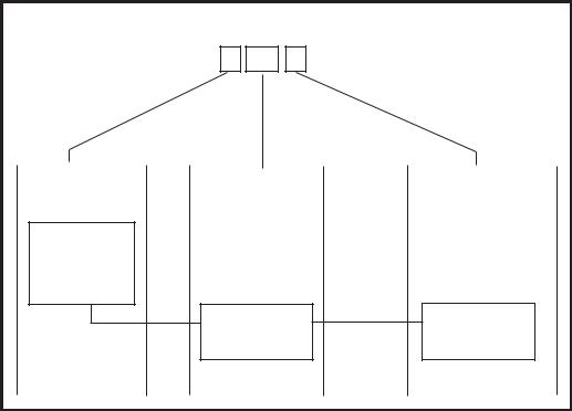
RS485 Data Communication Bus (AB Lines)
Communication between the Galaxy control panels and the modules attached to the system takes place on the AB lines. The communication protocol is RS 485 format. The control panel constantly monitors the modules attached to it.Abreak in the communication from any of the modules generates a module tamper alarm
RS485 Wiring Configurations
The system must be wired in a daisy-chain configuration. That is the A line from the previous module is connected to the A terminal of the current module and then on to the A line of the next module.
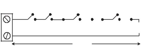
The RS485 (AB) line must have a 680 Ωresistor fitted across the A and B terminals of the last module on the line. If two lines are connected, both ends must be terminated with 680 Ωresistors and the appropriate link (LK3 or LK5) removed.
|
|
|
Keypad/Keyprox |
|
|
|
|
|
OR |
|
|
Galaxy |
|
|
Module |
|
|
|
|
|
|
||
Control |
A |
B |
A |
B |
|
Panel |
|||||
A |
|
|
|
||
680 Ω |
|
|
|
||
B |
|
|
|
||
|
|
|
680 Ω EOL |
||
|
|
|
|
||
|
Fit LK3/LK5 on PCB |
|
|
|
Figure 2-6. Daisy Chain Configuration
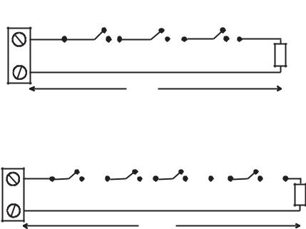
Each AB line can run in two directions from the control panel.
•Remove link LK3 (RS485 line1) or link LK5 (RS485 line2).
•Run two lines from theAand B terminals of the line.
•Terminate both Ends of Line (EOL) with a 680 ohm resistor.
NOTE: It is permissable to have different configurations on each line. For example, line 1 - Daisy chain; line 2 - twinAB daisy chain.
2-8
Galaxy Dimension Installer Manual |
RS485 Recommendations |
|
|
Keypad/Keyprox |
Keypad/Keyprox |
OR |
OR |
Module |
Module |
|
|
Galaxy |
|
|
Control |
A |
B |
Panel |
A |
A |
B |
B |
|
|
680 Ω EOL |
|
|
680 Ω EOL |
|
|
|
Remove |
|
|
|
LK3/LK5 |
|
|
|
|
|
Figure 2-7. TwinAB Line Daisy-Chain configuration |
||
RS485 Wiring Recommendations
To ensure that the system communicates at the maximum level of efficiency, the following recommendations must be adhered to:
1.The maximum number of devices on each line are:
|
|
|
|
|
|
|
|
GD-48 |
GD-96 |
GD-264 |
|
GD-520 |
|
|
(Line 1 only) |
(Lines 1-2) |
(Lines 1-2) |
(Lines 1-4) |
||
Keypads |
8 |
8 per line |
8 per line |
|
8 per line |
|
|
|
|
|
|
|
|
Keyprox |
3 |
3 (line 1) |
3 (line 1) |
|
3 (line 1) |
|
4 (line 2) |
4 (line 2) |
7(lines 2, 3, 4) |
||||
|
|
|||||
Touch Center |
1 |
1 per line |
1 per line |
|
1 per line |
|
|
|
|
|
|
|
|
RIO's/SPSU's |
4 |
4 (line 1) |
15 (line 1) |
|
15 (line1) |
|
6 (line 2) |
16 (line 2) |
16 (lines 2, 3, 4) |
||||
|
|
|||||
RF RIO |
4 |
4 (line 1) |
15 (line 1) |
|
15 (line 1) |
|
6 (line 2) |
16 (line 2) |
16 (lines 2, 3, 4) |
||||
|
|
|||||
|
|
|
|
|
|
|
MAX/DCM |
4 |
8 per line |
8 per line |
|
8 per line |
|
|
|
|
|
|
|
|
RS232 |
1 |
1 (line 1 only) |
1 (line 1 only) |
1 |
(line 1 only) |
|
|
|
|
|
|
|
|
Telecoms |
1 |
1 (line 1 only) |
1 (line 1 only) |
1 |
(line 1 only) |
|
|
|
|
|
|
|
|
Printer |
1 |
1 (line 1 only) |
1 (line 1 only) |
1 |
(line 1 only) |
|
|
|
|
|
|
|
|
ISDN |
1 |
1 (line 1 only) |
1 (line 1 only) |
1 |
(line 1 only) |
|
|
|
|
|
|
|
|
Ethernet |
1 |
1 (line 1 only) |
1 (line 1 only) |
1 |
(line 1 only) |
|
|
|
|
|
|
|
|
Audio Interface |
1 |
1 (line 1 only) |
1 (line 1 only) |
1 |
(line 1 only) |
|
|
|
|
|
|
|
|
Table 2-5. Communication Devices
2.The system must be wired in a daisy-chain configuration. Spur and star configurations must not be used as they reduce the immunity to electrical interference.
3.The cable used must screened twisted pair (Part No W002) to connect the RS485 (AB) line. This would be CAT5 or Belden 8723 equivalent.
2-9
RS485 Recommendations |
Galaxy Dimension Installer Manual |
|
|
4.Shielded twisted pair cable, where used, is connected to the earthing pillar on the Galaxy control panel using the P-clip and nut supplied (refer to Figure 2-8).
5.The RS485 (AB) line must have a 680 Ωresistor fitted across the A and B terminals of the last module on the line. If twin lines are connected, both ends must be terminated with 680 Ωresistors and the appropriate link on the control panel PCB must be removed (refer to figure 2-7).
6.There must only be a single AB pair of wires in each of the cables.
7.The minimum supply voltage level is 10.5 Vd.c. with 12.5 Vd.c. being the recommended working minimum.
8.The power supply in the Galaxy control panel and remote power supplies must not be connected inparallel.
9.The 0 V of all remote power supplies should be connected in common to the 0 V of the Galaxy control panel.
10.Ensure that any extension loudspeakers are not wired in the same cable as an AB pair of wires.
11.Where possible, ensure that the AB cable is at least 30 centimetres away from any other cables.
12.Where possible, ensure that the AB cable does not run parallel to other cables for extended distances (maximum 5 metres).
AB connectors
A 


 B
B
data line |
data line |
RS 485 cable
Cable screen
|
Nut |
P-clip |
P-clip |
|
Earthing pillar |
(threaded) |
Figure 2-8. Connection of cable screen using P-Clip
2-10
Galaxy Dimension Installer Manual |
Zone Addresses |
|
|
Zones
The default setting for the zones on the Galaxy Dimension are as follows:
Zone 1001 = Final
Zone 1002 = Exit
All remaining zones = Intruder
Zone Addresses
Each zone has a four digit address; 1004, 4136. The address is made up of three reference numbers as shown inthefollowingfigure:
|
Example: 3057 |
|
||
|
3 |
05 |
7 |
|
Represents Panel |
Represents |
|
Represents |
|
Line No. |
RIO Address |
Zone No. 1-8 on |
||
|
|
|
|
RIO |
GALAXY |
|
|
|
|
PANEL |
|
|
|
|
1 2 3 4 |
|
|
|
|
|
RIO |
|
|
ZONE 7 |
|
ADDRESS 05 |
|||
|
|
|||
Figure 2-9. Zone Addresses
For example, zone 3057 is the detector connected to line 3, RIO 05, zone 7.
2-11
RIO Switch |
Galaxy Dimension Installer Manual |
|
|
Zone Addressing with Onboard RIO Switch (Line 0 Switch)
The RIO switch (SW3, dipswitch 8) controls the ordering of the on-board RIO’s. This dipswitch must be set before powering up the panel. Setting the switch to ONsets the on-board RIO1 to operate on line 0 and allows a RIO addressed as 1 to be connected to line 1, giving a total of 15 RIO’s on a GD-264 and GD-520. The RIO switch only needs to be activated when the full compliment of RIO’s is required, or when replacing a Galaxy 512 panel with a power supply/RIO already using address 1.
NOTE: The RIO switch is not functional on other variants. It defaults to the Switch off configuration.
Switch off (default) |
|
|
|
|
When the switch is set to this mode, the onboard RIO’s configure to the following addresses: |
||||
Onboard RIO0 |
Zone address range: |
1001-1008 |
Outputs: |
1001-1004 |
Onboard RIO1 |
Zone address range: |
1011-1018 |
Outputs: |
1011-1014 |
Switch on |
|
|
|
|
When the switch is set to this mode, the onboard RIO’s configure to the following addresses: |
||||
Onboard RIO0 |
Zone address range: |
1001-1008 |
Outputs: |
1011-1014 |
Onboard RIO1 |
Zone address range: |
0011-0018 |
Outputs: |
0011-0014 |
|
|
|
|
|
|
|
Panel |
On-Board RIO Address Range |
Total |
Max No of |
Valid External |
Total Zone |
|
|
|
on-board |
External RIO's |
RIO Addresses |
Addresses |
|
|
|
Zones |
(Line 1) |
(Line 1) |
(Switch ON) |
|
GD-48 |
1001 - 1008, 1011 - 1018 |
16 |
4 |
2 - 5 |
48 |
|
|
|
|
|
|
|
|
GD-96 |
1001 - 1008, 1011 - 1018 (switch off) |
16 |
4 |
2 - 5 |
96 |
|
|
|
|
|
|||
1001 - 1008, 0011 - 0018 (switch on) |
16 |
5 |
1 - 5 |
|||
|
|
|||||
|
|
|
|
|
|
|
GD-264 |
1001 - 1008, 1011 - 1018 (switch off) |
16 |
14 |
2 - 9, A - F |
264 |
|
|
|
|
|
|
||
|
1001 - 1008, 0011 - 0018 (switch on) |
16 |
15 |
1 - 9, A - F |
||
|
|
|||||
|
|
|
|
|
|
|
GD-520 |
1001 - 1008, 1011 - 1018 (switch off) |
16 |
14 |
2 - 9, A - F |
520 |
|
|
|
|
|
|||
1001 - 1008, 0011 - 0018 (switch on) |
16 |
15 |
1 - 9, A - F |
|||
|
|
|||||
|
|
|
|
|
|
Table 2-6. Zone Address Ranges
2-12
Galaxy Dimension Installer Manual |
Wiring Zones |
|
|
Wiring Zones
The zones on Galaxy Dimension panels can be Double Balanced (default) or End of Line. Zones can be programmed with different resistance ranges for zone status activation (see Parameter 51.46 = Parameters.Zone Resistance). Refer to Table 2-7 (Double Balanced) or Table 2-8 (End of Line) for details of the zone resistance and resulting conditions.The system default is Option 9, giving fault monitoring on 1k double balanced wiring.
NOTE: The circuit debounce time (the period the zone must remain in a state to register a change in condition) is 300 milliseconds by default.
|
|
|
|
|
|
|||
|
Option 01 - 1k |
Option 03 - 2k2 |
Option 05 - 4k7 |
Option 07 - 5K6 |
Option 09 - 1k Fault |
|||
|
|
|
|
|
|
|||
Tamper S/C |
0 - 800 |
0 - 1800 |
0 - 3700 |
0 -1400 |
0 - 800 |
|||
|
|
|
|
|
|
|
|
|
Low Res |
800 - 900 |
1800 |
- 2000 |
3700 - 4200 |
1400 |
- 2800 |
800 - 900 |
|
|
|
|
|
|
|
|||
Normal |
900 - 1200 |
2000 - 2500 |
4200 - 5500 |
2800 - 8400 |
900 -1200 |
|||
|
|
|
|
|
|
|||
High Res |
1200 - 1300 |
2500 - 2700 |
5500 - 6500 |
8400 - 9800 |
1200 - 1300 |
|||
|
|
|
|
|
|
|||
Open |
1300 - 12000 |
2700 - 12000 |
6500 - 19000 |
9800 - 12600 |
1300 - 3500 |
|||
|
|
|
|
|
|
|
|
|
Fault |
- |
|
- |
|
- |
|
- |
3500 - 4500 |
|
|
|
|
|
|
|
|
|
Masked |
12000 - 19000 |
12000 |
- 15000 |
19000 |
- 22000 |
12600 |
- 22000 |
4500 - 19000 |
|
|
|
|
|
|
|
|
|
Tamper O/C |
19000 - infinity |
15000 |
- infinity |
22000 |
- infinity |
22000 |
- infinity |
19000 - infinity |
|
|
|
|
|
|
|
|
|
Table 2-7. Double Balanced Zone Resistance and Conditions
Option 09 - 1k Fault Double-balanced (default)
The wiring in Figure 2-10 should be used if the detector uses combined fault and mask signalling.Amask condition is generated if an alarm and fault are signalled at the same time.Alternatively, if the detector has seperate fault and mask indications then the wiring in Figure 2-11 should be used.
|
1k |
|
|
|
|
|
|
|
3k |
|
|
|
|
|
|
|
|
|
|
|
|
|
|
|
|
|
|
|
|
|
|
|
|
|
|
Alarm N/C |
Tamper N/C |
Fault N/C |
Zone |
|
1k |
100 m
Figure 2-10. Option 09 - Double balanced 1k Fault Monitoring Wiring
|
1k |
|
|
|
|
|
|
3k |
|
|
|
|
|
|
|
12k |
|
|
||
|
|
|
|
|
|
|
|
|
|
|
|
|
|
|
|
|
|
|
|
|
|
|
|
|
|
|
|
|
|
|
|
|
|
|
|
|
|
|
|
|
|
Alarm N/C |
Tamper N/C |
Fault N/C |
Zone
Anti-Mask N/C
1k
100 m
Figure 2-11. Option 09 - Double balanced 1k Fault/Mask Monitoring Wiring NOTE: N/C = Normally Closed.
2-13
Wiring Zones (cont’d) |
Galaxy Dimension Installer Manual |
|
|
When this wiring mode is employed, only one detector which can report fault conditions should be connected to the zone.Amaximum of two detectors or contacts of any type should be connected to a zone when this mode is selected. It is recommended that zone cable lengths are kept below 100m in this configuration.
NOTE: The recommended maximum cable run from a zone to a detector is 500 metres in all other configurations.
|
Option 02 - 1k |
Option 04 - 2k2 |
Option 06 - 4k7 |
Option 08 - 5k6 |
Option 10 -1k Fault |
|
|
|
|
|
|
|
|
Tamper S/C |
0 - 800 |
0 - 1800 |
0 - 3700 |
0 - 1400 |
0 - 800 |
|
|
|
|
|
|
|
|
Low Res |
800 - 900 |
1800 - 2000 |
3700 - 4200 |
1400 - 2800 |
800 |
- 900 |
|
|
|
|
|
|
|
Normal |
900 - 1200 |
2000 - 2500 |
4200 - 5500 |
2800 - 8400 |
900 - 1200 |
|
|
|
|
|
|
|
|
High Res |
1200 - 1300 |
2500 - 2700 |
5500 - 6500 |
8400 - 9800 |
1200 |
- 1300 |
|
|
|
|
|
|
|
Fault |
- |
- |
- |
- |
1300 |
- 4500 |
|
|
|
|
|
|
|
Masked |
1300 - 12000 |
2700 - 12000 |
6500 - 19000 |
9800 - 19000 |
4500 - 19000 |
|
|
|
|
|
|
|
|
Open |
12000 - infinity |
12000 - infinity |
19000 - infinity |
19000 - infinity |
19000 - infinity |
|
|
|
|
|
|
|
|
Table 2-8. End of Line Zone Resistance and Conditions
Option 10 - 1k Fault End-Of-Line
The wiring in Figure 2-12 should be used if the mode is end-of-line. Fault and mask indications can only be signalled if the detector has seperate fault and mask indications.
|
3k |
|
|
|
|
|
|
12k |
|
|
||
|
|
|
|
|
|
|
|
|
|
|
|
|
|
|
|
|
|
|
|
|
|
|
|
|
|
Alarm N/C Tamper N/C |
Fault N/C |
Anti-Mask N/C |
1k |
Zone |
|
|
|
|
|
|
|
100 m
Figure 2-12. Option 10 - End of Line Zone/Detector wiring
When this wiring mode is employed, only one detector which can report fault conditions should be connected to the zone.Amaximum of two detectors or contacts of any type should be connected to a zone when this mode is selected. It is recommended that zone cable lengths are kept below 100m in this configuration.
NOTE: The recommended maximum cable run from a zone to a detector is 500 metres in all other configurations.
2-14
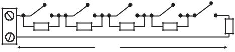
Galaxy Dimension Installer Manual |
Wiring Zones (cont’d) |
|
|
Wiring Multiple Detectors
Multiple detectors can be wired into a single zone when using preset 1 as shown in the following Figure. The maximum number of detectors that can be connected to a single zone is ten.
|
Alarm |
Alarm |
Alarm |
N/C |
N/C |
N/C |
N/C |
Zone |
1k |
1k |
1k |
|
1% |
1% |
1% |
500 m
Alarm (10 max) |
|
|
N/C |
N/C TAMP |
|
1k |
1% |
1k |
1% |
|
|
Figure 2-13. Zone to Multiple Detector Wiring
Wiring Keyswitches
Latching or spring loaded keyswitches can be used to set and unset the Galaxy Dimension panels; option 52 = PROGRAM ZONES has provision to accommodate both types of transition.
If the keyswitch latches, the transition from 1 kΩto 2 kΩinitiates the setting procedure of an unset system, the transition from 2 kΩto 1 kΩinstantly unsets a set system. If the system is already set, then the transition from 1 kΩto 2 kΩhas no effect. If the system is unset, the transition from 2 kΩto 1 kΩhas no effect. This is programmed as a Keyswitch in the PROGRAM ZONES option.
If the keyswitch is spring-loaded (returns to its normal position), the transition from 1 kΩto 2 kΩinitiates the setting procedure of an unset system and instantly unsets a set system, the transition from 2 kΩto 1 kΩ- the return to the normal position - has no effect. This is programmed as a Keyswitch in the PROGRAM ZONES option.
2-15
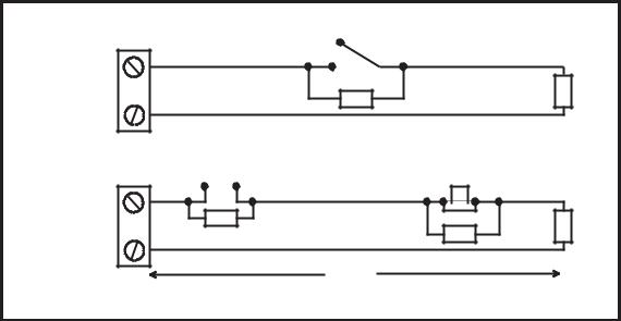
Terminator Zone Wiring |
Galaxy Dimension Installer Manual |
|
|
Wiring Terminator Buttons
Zones programmed as Push-Set (terminator) buttons can be open going closed (2 kΩto 1 kΩ) or closed going open (1 kΩto 2 kΩ). The first activation of the terminator button initialises its status to the system.
NOTE: The first activation of a terminator may not set the system as this can be the initialisation routine. If the system continues setting, push the button again. The system will set on the second push. This initialisation only occurs on the first setting.All subsequent setting routines set on the first push of the terminator.
The wiring of the terminator and keyswitch zone type is shown in the following figure:
Keyswitch |
1k to unset, 2k to set |
1k |
|
zone |
1k |
||
|
|||
|
1% |
|
1%
Open - Closed |
OR |
Closed - Open |
||||||
|
|
|
|
|
|
|
|
|
|
|
|
|
|
|
|
|
|
|
|
|
|
|
|
|
|
|
|
|
|
|
|
|
|
|
|
Push-set |
1k |
zone |
1% |
|
1% |
1k |
1k |
1% |
|
|
500m
Figure 2-14. Terminator and Keyswitch Zone Wiring
Outputs
The Galaxy Dimension control panel on-board outputs are detailed in the following table:
Output Address |
Default |
|
|
Normal State |
||
|
|
Type |
Rating |
|||
Default |
Line 0 Enable |
Function |
(with 3k3 pull-up) |
|||
|
|
|||||
|
|
|
|
|||
|
|
|
|
|
|
|
1001 |
1001 |
Bells |
Transistorised |
12V, 400mA |
Positive |
|
|
|
|
|
|
|
|
1002 |
1002 |
Strobe |
Single Pole |
30V, 1A |
De-energised |
|
|
|
|
Change Over |
|
|
|
|
|
|
Relay (SPCO) |
|
|
|
|
|
|
|
|
|
|
1003 |
1003 |
PA |
Transistorised |
12V, 400mA |
Positive |
|
|
|
|
|
|
|
|
1004 |
1004 |
Reset |
Transistorised |
12V, 400mA |
Positive |
|
|
|
|
|
|
|
|
1011 |
0011 |
Set |
Transistorised |
12V, 400mA |
Positive |
|
|
|
|
|
|
|
|
1012 |
0012 |
Intruder |
Transistorised |
12V, 400mA |
Positive |
|
|
|
|
|
|
|
|
1013 |
0013 |
Confirm |
Transistorised |
12V, 400mA |
Positive |
|
|
|
|
|
|
|
|
1014 |
0014 |
Reset |
Transistorised |
12V, 400mA |
Positive |
|
|
|
|
|
|
|
|
Table 2-9. Outputs
2-16
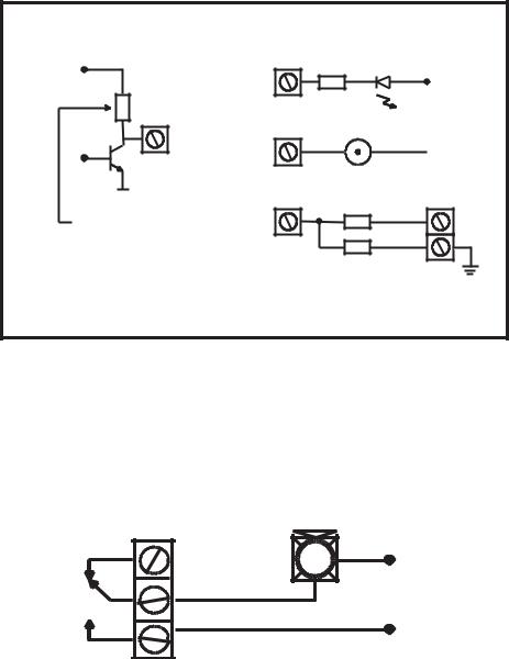
Galaxy Dimension Installer Manual |
Output Applications |
|
|
Output Applications
The outputs on the Galaxy panels, with the exception of the SPCO relay output, are transistorised outputs; negative applied (positive removed) by default. These supply up to 400 mA and can be used to drive the necessary output devices.
NOTE: The polarity of each output can be changed using option 53 = PROGRAM OUTPUTS
Transistorised Output
+12 V
3k3Ω
Output
0 V
Switch out 3k3Ω
to give open collector
|
Typical Applications |
A) LED |
|
Output |
LED |
|
|
|
+12 V |
|
1kΩ (typical) |
B) Bell |
Bell |
Output |
 + 12 V
C) Output used to trigger zone Output
* 1kΩ 1%
zone
Output must be |
1kΩ 1% |
open collector |
|
* NOTE: If the output used is one of the panel's on-board outputs, then substitute this resistor with a 680 Ω resistor.
Figure 2-15. Output Configuration and TypicalApplications
Note: For the appropriate 3k3Ωpull-up resistor refer to DIP switch SW3 (Table 2-1).
The relay output is a single pole change over; this can be used to drive output devices that require a clean set of contacts, isolated from the output voltage.
|
Horn |
|
Normally |
+12 V |
|
closed |
||
|
||
Single Pole |
|
|
Change - 0ver |
|
|
relay contacts |
|
|
Normally open |
0 V |
|
|
Figure 2-16. Single Pole Change–Over Relay Output Configuration and Typical application
2-17
Trigger Header |
Galaxy Dimension Installer Manual |
|
|
Trigger Header
The Trigger Header on the Galaxy Dimension is a set of pins that consist of programmable outputs for an external communication module. The connection is via an optional ribbon cable.
Trig 1-6
There are six trigger outputs, that can be used as communication triggers, but can also be used for any other purpose. By default these outputs are programmed as positive. They are designed to sink current (to 0V) not source current (from 12V). The function of these outputs are as follows:
|
|
|
|
Output |
Default |
Current (mA) |
|
Address |
function |
||
|
|||
0001 |
Fire |
100 |
|
|
|
|
|
0002 |
Panic |
100 |
|
|
|
|
|
0003 |
Intruder |
100 |
|
|
|
|
|
0004 |
Set |
100 |
|
|
|
|
|
0005 |
Omit |
100 |
|
|
|
|
|
0006 |
Confirm |
100 |
|
|
|
|
Table 2-10. Trigger Output functions
The function of the trigger outputs can be programmed in menu option 53 = Program Outputs.
Supply
A100 mA, 12V output is also provided. This output is fused by the on-boardAUX3 FUSE (F2).
+12V Not Used Not Used Trig 6 Trig 5 Trig 4 Trig 3 Trig 2 Trig 1 Not Used Not Used GND
Figure 2-17. Trigger Header
2-18
Loading...