


CLPS76ER ML-138258
Table of contents
 Loading...
Hobart CLPS76ER ML-138258, CLPS86E ML-138177, CLPS86E ML-138176, CLPS86ER ML-138281, CLPS76E ML-138107 User Manual
...
701 S. R IDGE AV ENUE
TRO Y, O HIO 4 5374- 0001
937 3 32-3000
www.h ob art co rp .co m
F44126 Rev. B (February 2011)
CLe-SERIES
DISHWASHERS
MODEL R-L OPERATION L-R OPERATION
CL44e ML-138101 ML-138102
CLPS66e ML-138103 ML-138104
CLCS66e ML-138109 ML-138110
CL54e ML-138105 ML-138106
CLPS76e ML-138107 ML-138108
CLCS76e ML-138111 ML-138112
CL64e ML-138174 ML-138175
CLPS86e ML-138176 ML-138177
CLCS86e ML-138178 ML-138179
CL44eR ML-138251 ML-138252
CLPS66eR ML-138253 ML-138254
CLCS66eR ML-138259 ML-138260
CL54eR ML-138255 ML-138256
CLPS76eR ML-138257 ML-138258
CLCS76eR ML-138261 ML-138262
CL64eR ML-138278 ML-138279
CLPS86eR ML-138280 ML-138281
CLCS86eR ML-138282 ML-138283

– 2 –
IMPORTANT FOR YOUR SAFETY
THIS MANUAL HAS BEEN PREPARED FOR PERSONNEL QUALIFIED
TO INSTALL GAS EQUIPMENT, WHO SHOULD PERFORM THE INITIAL
FIELD START-UP AND ADJUSTMENTS OF THE EQUIPMENT COVERED
BY THIS MANUAL.
POST IN A PROMINENT LOCATION THE INSTRUCTIONS TO BE
FOLLOWED IN THE EVENT THE SMELL OF GAS IS DETECTED. THIS
INFORMATION CAN BE OBTAINED FROM THE LOCAL GAS SUPPLIER.
IMPORTANT
IN THE EVENT A GAS ODOR IS DETECTED, SHUT DOWN UNITS
AT MAIN SHUTOFF VALVE AND CONTACT THE LOCAL GAS
COMPANY OR GAS SUPPLIER FOR SERVICE.
FOR YOUR SAFETY
DO NOT STORE OR USE GASOLINE OR OTHER FLAMMABLE
VAPORS OR LIQUIDS IN THE VICINITY OF THIS OR ANY OTHER
APPLIANCE.
FOR YOUR SAFETY
READ BEFORE OPERATING
DO NOT USE THIS APPLIANCE IF ANY PART HAS BEEN
UNDER WATER. IMMEDIATELY CALL A QUALIFIED SERVICE
TECHNICIAN TO INSPECT THE APPLIANCE AND TO REPLACE
ANY PART OF THE CONTROL SYSTEM AND ANY GAS
CONTROL WHICH HAS BEEN UNDER WATER.
IN THE EVENT OF A POWER FAILURE, DO NOT ATTEMPT TO
OPERATE THIS DEVICE.
© HOBART 2008

– 3 –
TABLE OF CONTENTS
GENERAL . . . . . . . . . . . . . . . . . . . . . . . . . . . . . . . . . . . . . . . . . . . . . . . . . . . . . . . . . . . . . . . . . . . . 4
Chemical Sanitizing . . . . . . . . . . . . . . . . . . . . . . . . . . . . . . . . . . . . . . . . . . . . . . . . . . . . . . . . . . 5
INSTALLATION . . . . . . . . . . . . . . . . . . . . . . . . . . . . . . . . . . . . . . . . . . . . . . . . . . . . . . . . . . . . . . . . 5
Unpacking . . . . . . . . . . . . . . . . . . . . . . . . . . . . . . . . . . . . . . . . . . . . . . . . . . . . . . . . . . . . . . . . . 5
Installation Codes . . . . . . . . . . . . . . . . . . . . . . . . . . . . . . . . . . . . . . . . . . . . . . . . . . . . . . . . . . . 5
Adjust Machine Height and Level Machine . . . . . . . . . . . . . . . . . . . . . . . . . . . . . . . . . . . . . . . . 5
Dish Table Assembly . . . . . . . . . . . . . . . . . . . . . . . . . . . . . . . . . . . . . . . . . . . . . . . . . . . . . . . . . 5
Water Requirements . . . . . . . . . . . . . . . . . . . . . . . . . . . . . . . . . . . . . . . . . . . . . . . . . . . . . . . . . 6
Plumbing Connections . . . . . . . . . . . . . . . . . . . . . . . . . . . . . . . . . . . . . . . . . . . . . . . . . . . . . . . . 7
Drain Connection . . . . . . . . . . . . . . . . . . . . . . . . . . . . . . . . . . . . . . . . . . . . . . . . . . . . . . . . 7
Water Connections . . . . . . . . . . . . . . . . . . . . . . . . . . . . . . . . . . . . . . . . . . . . . . . . . . . . . . . 7
Chemical Feeder Installations . . . . . . . . . . . . . . . . . . . . . . . . . . . . . . . . . . . . . . . . . . . . . . . . . . 8
Steam Connection (When Equipped for Steam Heat) . . . . . . . . . . . . . . . . . . . . . . . . . . . . . . . . 9
Gas Connection (When Equipped for Gas Heat). . . . . . . . . . . . . . . . . . . . . . . . . . . . . . . . . . . . 9
Venting Requirements . . . . . . . . . . . . . . . . . . . . . . . . . . . . . . . . . . . . . . . . . . . . . . . . . . . . . . 10
Type II Canopy Hood . . . . . . . . . . . . . . . . . . . . . . . . . . . . . . . . . . . . . . . . . . . . . . . . . . . . 10
Pant-Leg Vent Connections . . . . . . . . . . . . . . . . . . . . . . . . . . . . . . . . . . . . . . . . . . . . . . . 12
Exhaust Flow Requirements . . . . . . . . . . . . . . . . . . . . . . . . . . . . . . . . . . . . . . . . . . . . . . . 14
Electrical Connections – Dishwasher . . . . . . . . . . . . . . . . . . . . . . . . . . . . . . . . . . . . . . . . . . . 14
Optional Equipment Control Connections . . . . . . . . . . . . . . . . . . . . . . . . . . . . . . . . . . . . 16
CLeR Energy Recovery Set-up Instructions . . . . . . . . . . . . . . . . . . . . . . . . . . . . . . . . . . . . . . 16
CLeR Air Flow Adjustment . . . . . . . . . . . . . . . . . . . . . . . . . . . . . . . . . . . . . . . . . . . . . . . . . . . . 19
OPERATION . . . . . . . . . . . . . . . . . . . . . . . . . . . . . . . . . . . . . . . . . . . . . . . . . . . . . . . . . . . . . . . . . 21
Preparation . . . . . . . . . . . . . . . . . . . . . . . . . . . . . . . . . . . . . . . . . . . . . . . . . . . . . . . . . . . . . . . 21
Curtain Installation . . . . . . . . . . . . . . . . . . . . . . . . . . . . . . . . . . . . . . . . . . . . . . . . . . . . . . . . . . 22
Keypad and Display . . . . . . . . . . . . . . . . . . . . . . . . . . . . . . . . . . . . . . . . . . . . . . . . . . . . . . . . . 24
Filling the Dishwasher . . . . . . . . . . . . . . . . . . . . . . . . . . . . . . . . . . . . . . . . . . . . . . . . . . . . . . . 25
Starting the Gas Heat Dishwasher . . . . . . . . . . . . . . . . . . . . . . . . . . . . . . . . . . . . . . . . . . . . . 25
Minimum Temperatures . . . . . . . . . . . . . . . . . . . . . . . . . . . . . . . . . . . . . . . . . . . . . . . . . . . . . . 25
High-Temperature Operation . . . . . . . . . . . . . . . . . . . . . . . . . . . . . . . . . . . . . . . . . . . . . . 25
Low-Temperature Operation . . . . . . . . . . . . . . . . . . . . . . . . . . . . . . . . . . . . . . . . . . . . . . . 26
Alternative Temperature Display Names . . . . . . . . . . . . . . . . . . . . . . . . . . . . . . . . . . . . . . . . . 26
Low FR Temp Alert . . . . . . . . . . . . . . . . . . . . . . . . . . . . . . . . . . . . . . . . . . . . . . . . . . . . . . . . . 26
Tank Temperature Alert . . . . . . . . . . . . . . . . . . . . . . . . . . . . . . . . . . . . . . . . . . . . . . . . . . . . . . 26
Dishwashing . . . . . . . . . . . . . . . . . . . . . . . . . . . . . . . . . . . . . . . . . . . . . . . . . . . . . . . . . . . . . . 27
Optional Table Limit Switch . . . . . . . . . . . . . . . . . . . . . . . . . . . . . . . . . . . . . . . . . . . . . . . . . . . 28
Auto-Timer . . . . . . . . . . . . . . . . . . . . . . . . . . . . . . . . . . . . . . . . . . . . . . . . . . . . . . . . . . . . . . . . 28
Energy Saver Mode . . . . . . . . . . . . . . . . . . . . . . . . . . . . . . . . . . . . . . . . . . . . . . . . . . . . . . . . . 28
Dirty Water Mode . . . . . . . . . . . . . . . . . . . . . . . . . . . . . . . . . . . . . . . . . . . . . . . . . . . . . . . . . . . 28
CLEANING . . . . . . . . . . . . . . . . . . . . . . . . . . . . . . . . . . . . . . . . . . . . . . . . . . . . . . . . . . . . . . . . . . 28
Deliming Recommendations . . . . . . . . . . . . . . . . . . . . . . . . . . . . . . . . . . . . . . . . . . . . . . . . . . 30
DOs and DON'Ts for Your New Hobart Warewasher . . . . . . . . . . . . . . . . . . . . . . . . . . . . . . . . 31
PROGRAMMING . . . . . . . . . . . . . . . . . . . . . . . . . . . . . . . . . . . . . . . . . . . . . . . . . . . . . . . . . . . . . . 32
Programming Security Levels . . . . . . . . . . . . . . . . . . . . . . . . . . . . . . . . . . . . . . . . . . . . . . . . . 32
Programming Instructions . . . . . . . . . . . . . . . . . . . . . . . . . . . . . . . . . . . . . . . . . . . . . . . . . . . . 33
Menu Display Prompts . . . . . . . . . . . . . . . . . . . . . . . . . . . . . . . . . . . . . . . . . . . . . . . . . . . . . . . 33
Entering the Parameters Menu . . . . . . . . . . . . . . . . . . . . . . . . . . . . . . . . . . . . . . . . . . . . . . . . 34
Navigating the Parameters Menu . . . . . . . . . . . . . . . . . . . . . . . . . . . . . . . . . . . . . . . . . . . . . . 34
Parameters Menu . . . . . . . . . . . . . . . . . . . . . . . . . . . . . . . . . . . . . . . . . . . . . . . . . . . . . . . . . . 35
Communications Setup Menu . . . . . . . . . . . . . . . . . . . . . . . . . . . . . . . . . . . . . . . . . . . . . . . . . 36
MAINTENANCE . . . . . . . . . . . . . . . . . . . . . . . . . . . . . . . . . . . . . . . . . . . . . . . . . . . . . . . . . . . . . . 36
Vent . . . . . . . . . . . . . . . . . . . . . . . . . . . . . . . . . . . . . . . . . . . . . . . . . . . . . . . . . . . . . . . . . . . . . 36
Lubrication . . . . . . . . . . . . . . . . . . . . . . . . . . . . . . . . . . . . . . . . . . . . . . . . . . . . . . . . . . . . . . . . 36
Service . . . . . . . . . . . . . . . . . . . . . . . . . . . . . . . . . . . . . . . . . . . . . . . . . . . . . . . . . . . . . . . . . . . 36
TROUBLESHOOTING . . . . . . . . . . . . . . . . . . . . . . . . . . . . . . . . . . . . . . . . . . . . . . . . . . . . . . . . . 37

– 4 –
Installation, Operation and Care Of
CLe and CLeR-SERIES DISHWASHERS
SAVE THESE INSTRUCTIONS
GENERAL
CLe and CLeR machines are rack-type warewashers that move the racks from one end
of the machine to the other, exposing the ware to progressive wash and rinse zones.
(Pumps and nal rinse are activated by the inserted rack to energize the specic wash or
rinse action needed.) The CLe and CLeR-series machines are offered in optional lengths,
sections, features, and provide different speeds to meet productivity and performance
requirements. (All CLe and CLeR-Series Dishwashers have electronic controls with digital
temperature displays.)
The CLeR models have an energy recovery system and include all of the standard features
of the CLe. They use an internal condensing system to capture the water vapor and preheat
incoming cold water for the nal rinse. The CLeR units are only available in hot water
sanitizing mode, three phase, and come standard with a built-in 30kW booster heater,
which is designed to maintain nal rinse temperature of 180°F with a minimum incoming
cold water temperature of 55 °F.
Tanks, chambers, frames, legs and adjustable feet are made of welded stainless steel
construction. Hinged inspection doors provide access to the interior wash and rinse zones.
CLPS models provide a 22-inch power scrapper section and hinged access door. The power
scrapper removes the heavy soil before the rack enters the wash zone.
Machines can be ordered as left-to-right or right-to-left operation. Either electric, gas, or
steam tank heat is specied at time of order. Machines come standard ready to operate
with high-temperature sanitizing mode.
Hobart offers three right-angle possibilities to put your machine in a corner installation:
• The Side Loader moves the rack at a right angle into the machine from the scrapping
area.
• The Direct Drive Unloader moves the rack at a right angle coming out of the machine to
tabling where the clean ware can be unracked.
• The Corner Scrapper (CLCS models) puts a Power Scrapper in the corner location at
the load end of your machine, combining right angle entry with a scrapper section.

– 5 –
CHEMICAL SANITIZING
CLe machines can be converted to operate with low-temperature sanitizing mode
(with the use of chemical sanitizers). Refer to Sanitizing Mode programming
instructions on page 34.
Hot water sanitizing mode is designated by "High Temp." on the display when the
machine is turned on. Low-temperature or chemical sanitizing mode is designated
by "Low Temp." on the display when the machine is turned on.
CLe models that operate with chemical sanitization, use incoming water and nal
rinse water at 120°F minimum. Tank heaters raise that temperature to 130°F for
wash (and power rinse, if equipped).
INSTALLATION
UNPACKING
Immediately after unpacking the dishwasher, check for possible shipping damage.
If the machine is found to be damaged, save the packaging material and contact
the carrier within 15 days of delivery.
Prior to installation, verify that the electrical service agrees with the specications
on the machine data plate, which is located on the left-hand side of the control box.
After unpacking the dishwasher, remove the items shipped loose (overow tube
or standpipe, splash shields, curtains and literature envelope with instructions and
chamber hole plug kit) from inside the dishwasher.
INSTALLATION CODES
Installation must be in accordance with state and local codes, or in the absence
of local codes, with the National Fuel Gas Code, ANSI Z223.1 (latest edition), if
applicable, and the National Electrical Code ANSI / NFPA 70 (latest edition). In
Canada, the installation standards are: CAN/CSA B149.1 and CSA C22.1 (latest
editions).
CLeR MODELS
If the unit will not t thru verticle opening, the overall height of the unit can be
decreased 7" by removing the vent stack.
ADJUST MACHINE HEIGHT AND LEVEL MACHINE
Set the dishwasher in its proper location. Adjust the height and level the machine
by turning the adjustable feet in or out as necessary.
DISH TABLE ASSEMBLY
Dish tables should be tted into the dishwasher (Figs. 1, 2 & 3). Use silicone sealant
between table and lip of tank to prevent leakage. Rack track height should be
from
1
/4 to
5
/16" (Fig. 2) above the tank lip. Dish tables should be sloped so that any
water carried from the dishwasher will drain back into the machine, but not from
the scrapping area.
NOTE: The dishwasher must be in its nal position, adjusted for proper height and
properly leveled before table assembly and plumbing connections are made.

– 6 –
Fig. 1
Fig. 2
Fig. 3
WATER REQUIREMENTS
Proper water quality can improve ware washing performance by reducing spotting,
enhancing effectiveness of labor and extending equipment life. Water conditions
vary from one location to another. The recommended proper water treatment for
effective and efcient use of this equipment will also vary depending on the local
water conditions. Ask your municipal water supplier for details about local water
specics prior to installation.
Recommended water hardness is 3 grains of hardness per gallon or less. Chlorides
must not exceed 30 parts per million. Water hardness above 3 grains per gallon
should be treated by a water conditioner (water softener or in-line treatment). Water
treatment has been shown to reduce costs associated with machine cleaning,
reduce deliming of the dishwasher and reduce detergent usage in the dishwasher.
Sediment, silica, chlorides or other dissolved solids may require particulate ltration
or other water treatment.
If an inspection of the dishwasher or booster heater reveals lime buildup after
the equipment has been in service, in-line water treatment is recommended.
Contact your local Hobart Service ofce for specic recommendations.
– 7 –
PLUMBING CONNECTIONS
Plumbing connections must comply with applicable sanitary,
safety and plumbing codes.
The plumber who connects this machine is responsible for making certain that both
water and steam lines are THOROUGHLY FLUSHED OUT BEFORE connecting to
any manual valve or solenoid valve.
This ‘‘ush-out’’ is necessary to remove all foreign matter, such as chips (resulting
from cutting or threading of pipes), pipe joint compound from the lines or, if soldered
ttings are used, bits of solder or cuttings from the tubing. Debris, if not removed,
may lodge in the valves and render them inoperative. Manual valves or solenoid
valves found defective by foreign matter and any expenses resulting from this debris
are NOT the responsibility of the manufacturer.
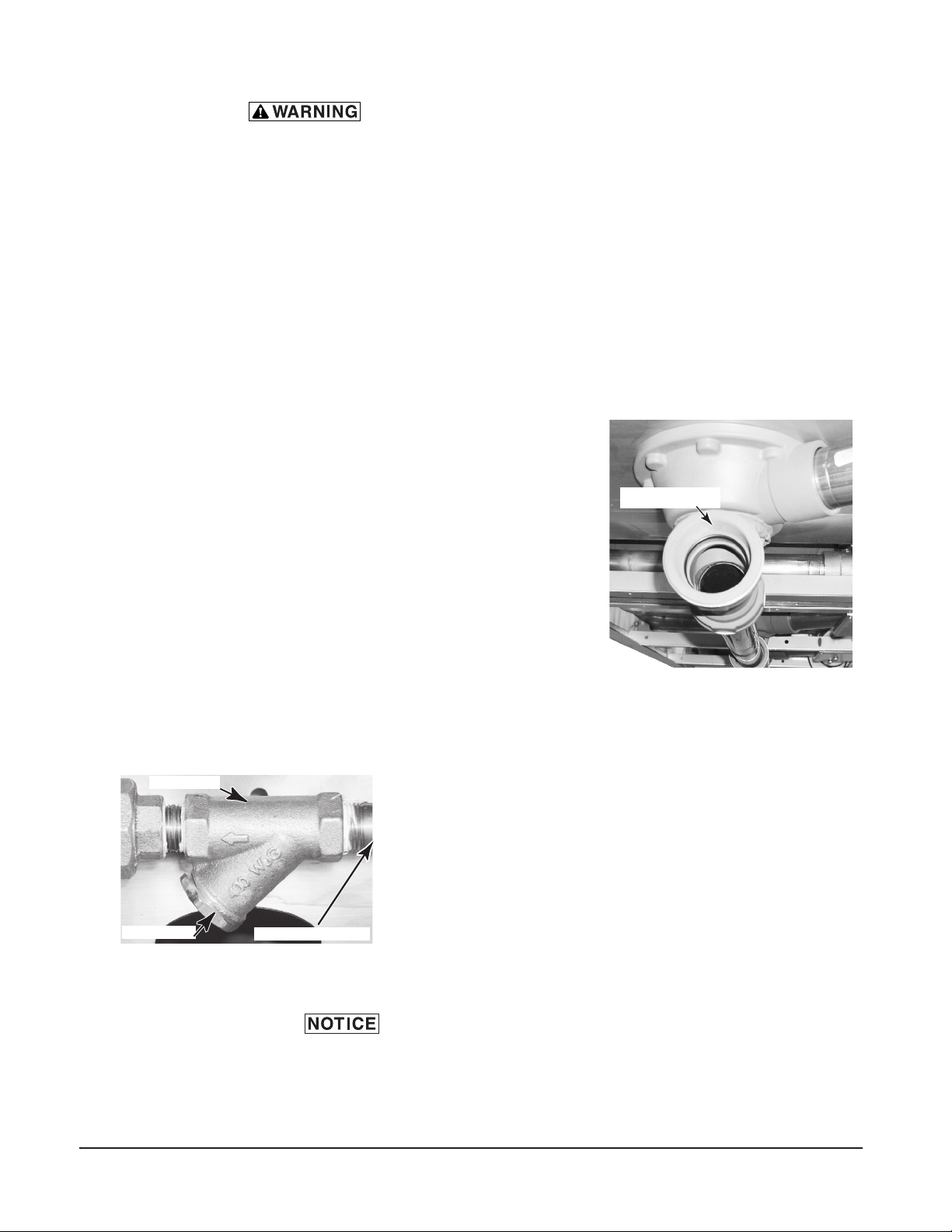
DRAIN CONNECTION
The common drain for the tank(s) requires only
one connection to the oor drain. The drain
can be connected at either end. A pipe plug
is provided for the opposite end. Connect the
drain (Fig. 4) through a trap to the sewer using
2" NPT pipe. If a grease trap is required by
code, it should have a minimum ow capacity
of 31 gallons per minute.
WATER CONNECTIONS
Use
1
/2" minimum I.D. pipe size for the incoming water supply
line to the machine (Fig. 5). A owing pressure of 15 to 25
psig must be maintained at the machine. For long runs, use
larger pipe and insulation to ensure adequate pressure and
temperature. On CLe models without built-in booster heater,
if ow pressure exceeds 25 psig, a pressure-reducing valve
(by others) must be installed in the water supply line. On CLe
models with built-in booster heater and all CLeR models, pressure
reducing valves are factory installed in the water supply lines.
For temperature requirements, refer to the Required Incoming
Water Temperature table on page 8.
The water pressure regulator must have a relief bypass. Failure
to use the proper type of pressure regulator may result in damage to the
machine.
A pressure gauge is provided for verication of proper water pressure.
DRAIN CONNECTION
AT EITHER END
Fig. 4
Fig. 5
CLEANOUT
INCOMING WATER
STRAINER
– 8 –
CHEMICAL FEEDER INSTALLATIONS
This machine must be operated with an automatic detergent feeder and, if
applicable, an automatic chemical sanitizer feeder, including a visual means
to verify that detergents and sanitizers are delivered or a visual or audible
alarm to signal if detergents and sanitizers are not available for delivery
to the respective washing and sanitizing systems. Chemical feeders are
supplied by others. For electrical connection, refer to Optional Equipment
Control Connections, page 16.
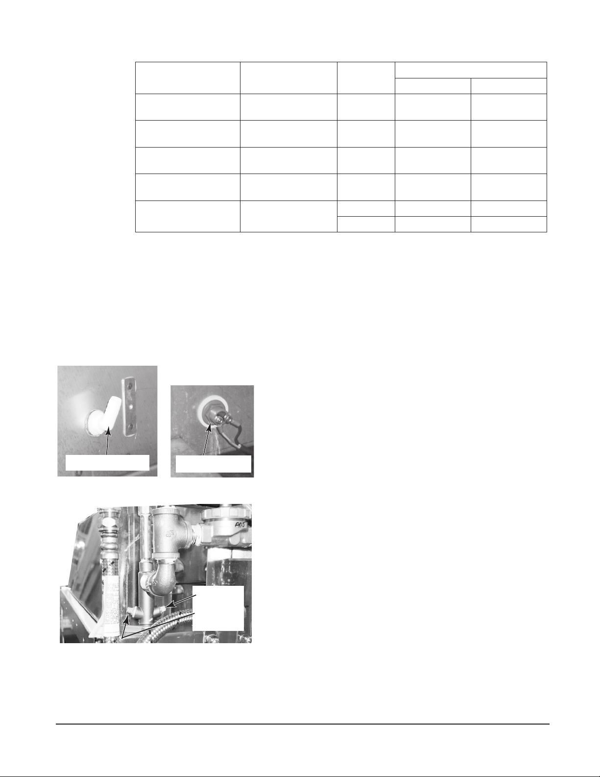
Detergent Feeder
Your chemical supplier will install a detergent feeder port
similar to the one shown in Fig. 6, that provides for discharge
of detergent into the wash tank.
An electric monitoring device, similar to the one shown in
Fig. 7, will be installed on the side of the wash tank to signal
the feeder to maintain the proper concentration of detergent.
Rinse Agent Feeder
Rinse agent is typically fed into the nal rinse water at one
of the ports on the incoming water line below the pressure
gauge (Fig. 8).
Chemical Sanitizer Feeder
Chemical sanitizer (on
CLe machines using low-temperature
sanitizing) is fed into the nal rinse water line at the other port
on the incoming water line below the pressure gauge (Fig. 8).
DETERGENT FEED PORT
(TYPICAL) (BY OTHERS)
DETERGENT SENSOR
(TYPICAL) (BY OTHERS)
RINSE AID
AND / OR
CHEMICAL
SANITIZER
FEED PORTS
Fig. 8
Fig. 6 Fig. 7
REQUIRED INCOMING WATER TEMPERATURE
Model Sanitizing Mode Connection Water Supply
Minimum Maximum
CLe without Built-in
Booster
Hot Water Sanitizing Hot Water
180
°F (82°C) 194°F (82°C)
CLe without Built-in
Booster
Chemical Sanitizing Hot Water
120
°F (49°C)
N/A
CLe with 15kW Built-
in Booster
Hot Water Sanitizing Hot Water
140
°F (60°C)
N/A
CLe with 30kW Built-
in Booster
Hot Water Sanitizing Hot Water
110
°F (43°C)
N/A
CLeR with 30kW
Built-in Booster
Hot Water Sanitizing Cold Water
55
°F (13°C)
N/A
Hot Water
110
°F (43°C)
N/A

– 9 –
STEAM CONNECTION (When Machine is Equipped with Steam Tank Heat)
Steam supply pressure must agree with the steam trap (supplied) which
is rated for 10 to 50 psig differential pressure. If owing pressure exceeds 50 psig,
a pressure regulator (by others) must be installed in the supply line. Steam ow is
controlled by solenoid valves.
For single-tank steam coil installations, two connections are required, one for
supply and one for return. For two-tank steam coil installations, one common supply
connection and two return connections are required.
GAS CONNECTION (When Machine is Equipped with Gas Tank Heat)
Check the gas data plate attached to the dishwasher on the side of the control
box or refer to the tag attached to the gas burner tubing for the type of gas to be
used. All machines are shipped congured for natural gas. If conversion to LP gas
(propane) is required, a conversion kit with instructions is supplied and must be
installed before the machine is operated.
The burner is not adjustable. If owing gas pressure is above 7" W.C. (natural gas)
or 11" W.C. (propane gas), an additional regulator valve (by others) must be installed
in the supply line. Static incoming line pressure should not exceed 14.0" W.C. for
either propane or natural gas.
The gas supply line to the dishwasher must be provided with a
shut-off valve per code. The appliance and its gas connections must be leak
tested before placing the appliance in operation. Use soapy water for leak
tests. DO NOT use an open ame.
The installation must conform with local codes, or in the absence of local codes,
with the National Fuel Gas Code, ANSI Z223.1 (latest edition), available from the
American Gas Association, Inc., 1515 Wilson Blvd., Arlington, VA 22209. In Canada,
comply with CAN/CSA B149.1 and CSA C22.1 (latest editions).
NOTE: For gas line pipe connections, use Loctite 565, Hobart part number 546292,
or a exible sealant suitable for use with Natural and Propane Gases.
• The appliance and its individual shutoff valve must be disconnected from the gas
supply piping system during any pressure testing of that system at test pressures
in excess of
1
/2 psig (3.45 kPa).
• The appliance must be isolated from the gas supply piping system by closing
its individual manual shutoff valve during any pressure testing of the gas supply
piping system at test pressures equal to or less than
1
/2 psig (3.45 kPa).
– 10 –
Dissipate test pressure from the gas supply line before reconnecting the appliance
and its manual shutoff valve to the gas supply line.
Failure to follow this procedure may damage the gas valve.
Gas heat machines must be provided with a means to exhaust
the ue gases to the exterior of the building.
Refer to Venting Requirements on pages 10 – 14.
The dishwasher must be installed so that the ow of combustion and ventilation
air will not be obstructed. Ensure that no electrical cables or plumbing are routed
over the gas ue area. Adequate clearances for air openings into the combustion
chamber must be provided. Make sure there is an adequate supply of make-up air
in the room to allow for combustion of the gas at the burner(s).
Keep the appliance area free and clear from all combustible substances. Do not
obstruct the ow of combustion and ventilation air. The dishwasher must have a
minimum clearance from combustible construction of 3" at the rear and 0" at the
sides. A clearance of 23" must be provided at the front and 20" at each end of the
dishwasher for servicing and proper operation.
The burner is ignited automatically by solid-state electronic circuitry. There is no
pilot light. Gas ow is regulated by the temperature control circuit.
VENTING REQUIREMENTS
CLeR units will require a back draft damper in the ventilation system.
(To be supplied and installed by others).
Type II Canopy Hood
Most commercial dishwashers must be provided with external venting per local
codes. The exception is electric or steam heat machines operating in the chemical or
low temperature sanitizing mode where the existing room ventilation will compensate
for the vapors produced. The local authority has nal jurisdiction over this matter.
Venting can be provided by either a canopy hood over the whole machine (Fig. 9)
or by the pant-leg duct connection (Fig. 10).
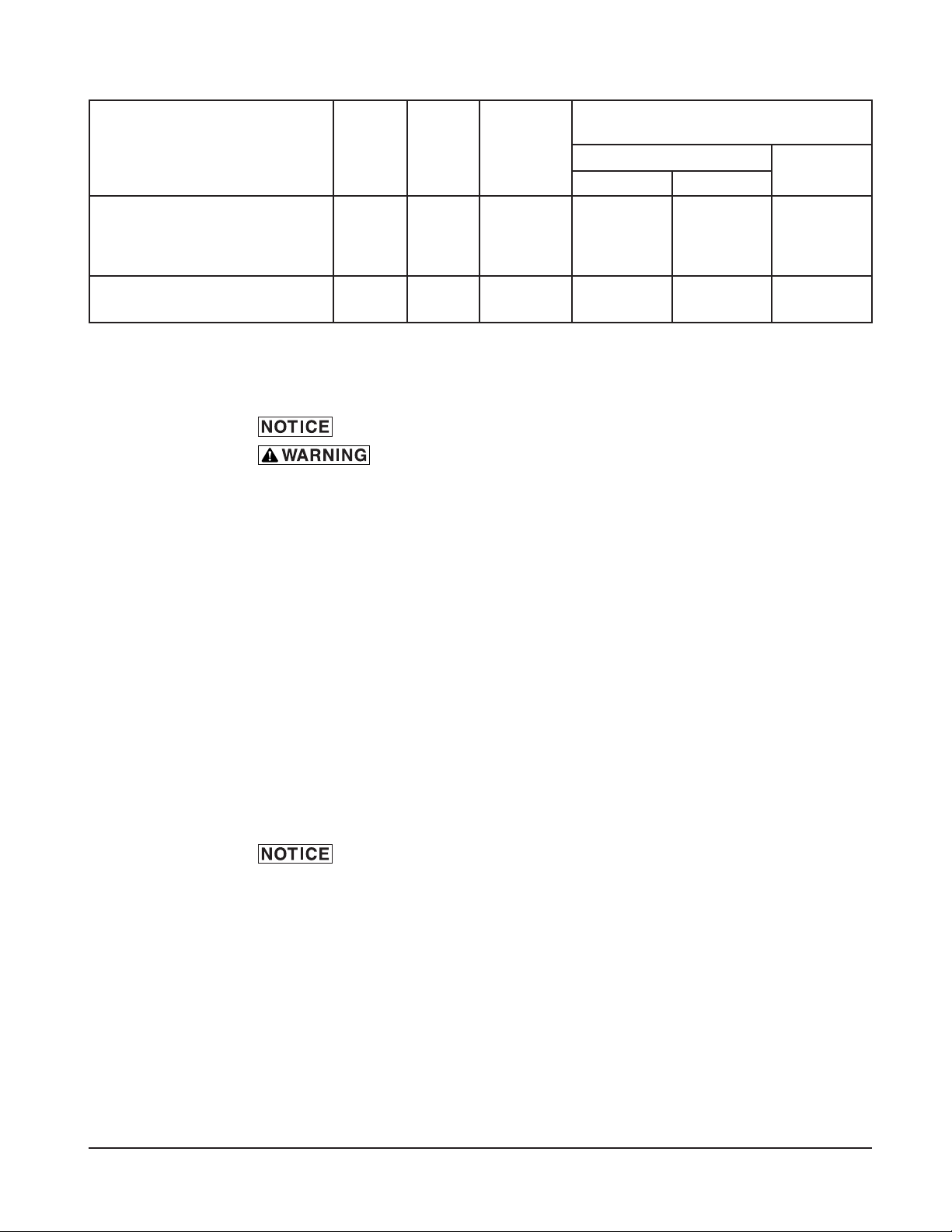
GAS SPECIFICATIONS
Models
Type of
Gas
BTU/Hr
Connection
Line Size
Flowing Gas Pressure - Not Static
Inches W.C. (Water Column)
Incoming Line Pressure
Manifold
Pressure
Minimum Maximum
CL44e, CLPS66e, CLCS66e
CL54e, CLPS76e, CLCS76e
CL44eR, CLPS66eR, CLCS66eR
CL54eR, CLPS76eR, CLCS76eR
Natural
Propane
78,000
78,000
1/2" NPT
1/2" NPT
3.5" W.C.
9.0" W.C.
7.0" W.C.
11.0" W.C.
3.2" W.C.
8.2" W.C.
CL64e, CLPS86e, CLCS86e
CL64eR, CLPS86eR, CLCS86eR
Natural
Propane
156,000
156,000
3/4" NPT
3/4" NPT
3.5" W.C.
9.0" W.C.
7.0" W.C.
11.0" W.C.
3.2" W.C.
8.2" W.C.
– 11 –
A Hobart CLe or CLeR Series dishwasher equipped for gas tank heat is not provided
with a ue collar and is not intended to have the ue directly connected to a ventilation
system. However, the products of combustion must be vented to the outside air.
Exhaust air must not be vented into a wall, a ceiling, or a concealed space of a
building. A vent hood over the entire dishwasher (Fig. 9) can be employed to vent
both the moist air from the dishwashing chamber and the ue gases from the gas
heater. The volume of ue exhaust required for venting moist air and ue gases
using a single vent hood over the entire dishwasher must be calculated using the
Exhaust Flow Requirements on page 14.
A Type II canopy hood is recommended. A factory-built commercial exhaust hood
may be listed as conforming to Underwriters Laboratory's Standard 710 titled, Exhaust
Hoods for Commercial Cooking Equipment. Hoods must be installed according to
the manufacturer's instructions. Makeup air must be provided so that the exhaust
ow rate results in a positive building pressure in the room where the unit is located
(more outside air than exhaust air). Factory-built hoods not tested to UL Standard
710 and custom built hoods must comply with the following specications: They
must be built from stainless steel, 0.037" [No. 20 Gage] minimum thickness, or
copper sheet weighing at least 24 ounces per square foot; the hood must be secured
in place by noncombustible supports and the hood must meet the Exhaust Flow
Requirements on page 14.
Fig. 9
TYPE II
CANOPY HOOD
40504<46=,9/(5.
(;36(+(5+<536(+
67,505.:
,?/(<:;+<*;:/6<3+
),*,5;,9,+05/66+
40504<46=,/(5.
-965;)(*2
CLe-SeriesCLeR-Series
;6
*3,(9(5*,
;6
CLEARANCE
19 1/8"

– 12 –
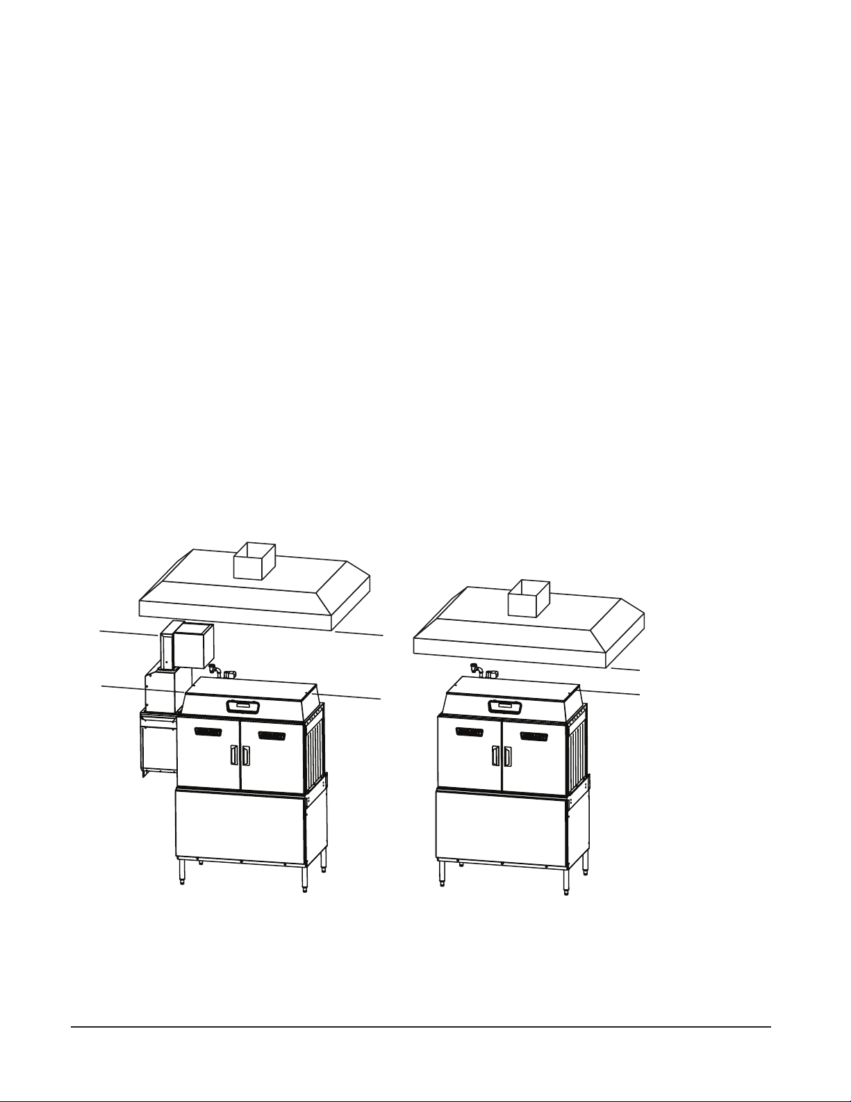
Pant-Leg Vent Connections
Gas heat machines must be provided with a means to exhaust
the ue gases to the exterior of the building.
Pant-Leg duct connectors (Fig. 10) alone DO NOT provide ventilation for the gas
ue at the rear of the machine. A mini-vent hood (Fig. 11) must be used or a canopy
type hood may be used (Fig. 9).
Moist air escapes from each end of the conveyor type dishwasher. The recommended
exhaust requirement is 200 CFM (CLe and CLeR) at the entrance end of the dishwasher
and 400 CFM (CLe)/175 CFM (CLeR) at the discharge end. Optional vent hoods or
extended hoods may be provided at each end of the machine. Sufcient make-up
air must be provided so the exhaust ow results in a positive building pressure in
the room in which the unit is located (more outside air than exhaust air). Hoods are
provided with 4" x 16" vent connectors with vent dampers which allow adjustment
during installation. Typical construction is for 'Pant-Leg' hood connections to the 4"
x 16" vent connectors (Fig. 10). Vent stacks must be watertight and t inside the
vent connector openings.
If using the 'Pant-Leg' duct, a mini-vent hood (Fig. 11) must be used to vent the
ue gases on machines using gas heat. The mini-vent hood must be positioned
a minimum of 18" above the ue exit at the rear of the dishwasher and connected
to existing duct work. The volume of ue exhaust in the mini-vent hood should not
exceed 200 CFM.
In either case, if a powered means of exhaust is used, an electrical interlock
must be provided to allow the ow of gas to the dishwasher burner only when
the exhaust system is in operation.
For more information, refer to the National Fuel Gas Code, ANSI Z223.1, NFPA54.
In all cases, local codes will prevail.
Loading...