How it Works
Log In / Sign Up
0
My Files
0
My Downloads
329106
History
Account Settings
Log Out
Buy Points
How it Works
FAQ
Contact Us
Questions and Suggestions
Users
Hobart
Loading...
C
CRS110A
CRS66
CRS-76
CUS48
CYBER FLEX 652
D
D-300
2
D300 ML-134258
D340
2
DA2
DDU38e
2
DDUe
DE1
DGC1
DGC5X
DRO2E
DRO2G
DRO2GH
3
DWT-AM15
DWT-CLe
DX50
E
EDGE
EDGE-12
3
EDGE13-11
2
EL20-2142
EL5-1124
EL5-1224UC
EPCP
EPCP-5HTi
2
EPP-1
ES5
ES600
ET12
ET-20
2
ET40
F
F-35521
F5-1224UC
F-8018
FD2-200
FD3-150
2
FD3-300
FD3-50
FD4-125
2
FD4-150
FOODWASTE DISPOSER REPLACEMENT CONE ADAPTERS
FP250
FP300
FRC100A
FRCLe
FT1000
FT1000D
FT1000-ER
FT-600
FT800
3
FT800W
FT900
3
FT900BD
FT900D
FW-151
G
GFO65A
H
H190G
H600
2
H600C
2
H-600-T
H-9
Handler 120
HBA2G
HBR300-1
HBR301
HBR301-1
HBR301-160
HCB47
HCE6H
HCG1
2
HCG40D
HCM300
HCM-300C
HCM450
2
HCN50
HCO18E
HCR40
HCR411
HE12HT
HEC3018
HEC501
2
HEC501X
HEC5DX
HEC5 SERIES
HEC5X SERIES
HECV5X
HEF225
HF250B
HF270
HFBMW2
HG2
HG4
HGC20
HGC5 SERIES
HGC5X SERIES
HGC-601
HGC65F
Loading...
Loading...
Nothing found
FT1000-ER
User Manual
44 pgs
2.49 Mb
0
Operation Manual
84 pgs
2.66 Mb
0
Installation Instructions Manual
140 pgs
8.08 Mb
0
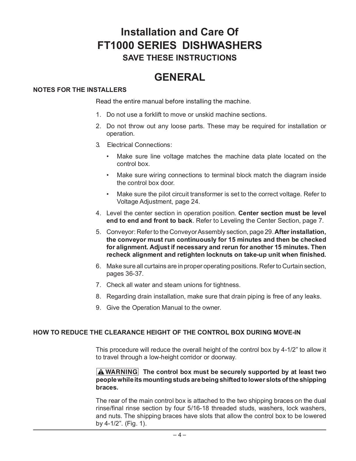
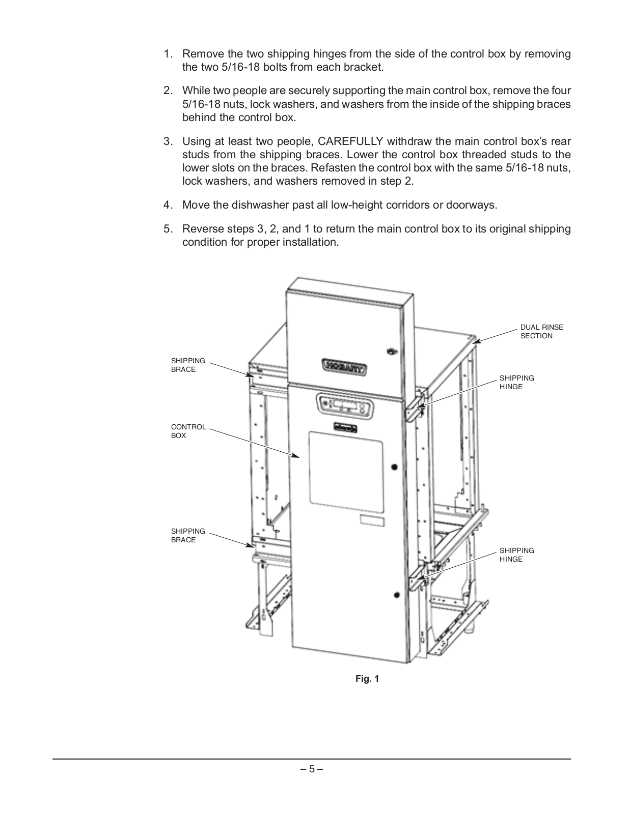
Table of contents
Loading...
Hobart FT1000-ER, FT1000, FT1000-ER-BD, FT1000S, FT1000S-ER-BD User Manual
...
Hobart FT1000-ER, FT1000, FT1000-ER-BD, FT1000S, FT1000S-ER-BD, FT1000S-ER User Manual
Download
Loading...
+
30
hidden pages
Unhide
You need points to download manuals.
1 point = 1 manual.
You can buy points or you can get point for every manual you upload.
Buy points
Upload your manuals
 Loading...