


Hobart AM15T-2 Service Manual
AM15 DISHWASHER TECHNICAL MANUAL 208-240V/60/3
SPECIFICATION SHEET INSTALLATION INSTRUCTIONS OPERATION INSTRUCTIONS CLEANING INSTRUCTIONS MAINTENANCE INSTRUCTIONS TROUBLE SHOOTING INSTRUCTIONS WIRING DIAGRAMS
CATALOG OF REPLACEMENT PARTS SMARTPARTS™ USER GUIDE RECOMMENDED SPARE PARTS LIST

Need other Hobart Services?
•Warranty Registration
•Delivery and Installation
•Preventive Maintenance
•Hobart Service Contracts
•Extended Warranty Contracts
•Parts and Accessories
•Specialty Programs
•Water Treatment Programs
AM15 Dishwasher Technical Manual Page 2 of 83

Item #______________________________________
Quantity____________________________________
C.S.I. Section 11400
|
|
|
|
|
|
|
|
AM SELECT |
|
|
701 S Ridge Avenue, Troy, OH 45374 |
|
DISHWASHER |
|
|
|
|
|
|
|
1-888-4HOBART • www.hobartcorp.com |
|
|
|
|
|
|
|
|
|
|
|
|
|
|
|
|
|
|
|
|
|
|
|
STANDARD FEATURES
■.74 gallons per rack final rinse water
■58 racks per hour – hot water sanitizing
■65 racks per hour – chemical sanitizing
■NSF pot and pan listed for 2-, 4- & 6- minute cycles
■Timed wash cycles for 1, 2, 4 or 6 minutes
■Solid state, integrated controls with digital status indicators
■Self-draining, high efficiency stainless steel pump and stainless steel impeller
■Stainless steel drawn tank, tank shelf, chamber, trim panels, frame and feet
■Spring counterbalanced chamber with polyethylene guides
■Revolving, interchangeable upper and lower anticlogging wash arms
■Revolving, interchangeable upper and lower rinse arms
■Slanted, self-locating, one-piece scrap screen and basket system
■Automatic fill
■Door actuated start
■Automatic drain closure
■Vent fan control
■External booster activation
■Delime cycle
■Service diagnostics
■NAFEM Data Protocol capable
■Straight-through or corner installation
■Hot water or chemical sanitation
VOLTAGE
208-240/60/1
208-240/60/3
480/60/3
200-240/50/3*
380-415/50/3*
*Not submitted for UL/CUL Listing
MODEL
AM15
OPTIONS AT EXTRA COST
Gas heat
Sense-A-Temp™ 70°F rise electric booster heater
Single point electrical connection for booster equipped machines (3 phase only)
ACCESSORIES
3⁄4" pressure regulator valve
Peg rack
Combination rack
Splash shield for corner installations
Flanged and seismic feet
End of cycle audible alarm (field activated)
Delime notification (field activated)
Drain water tempering kit
Specifications, Details and Dimensions on Inside and Back.
F-40078 – AM Select Dishwasher |
Page 1 of 8 |
DISHWASHER SELECT AM
AM15 Dishwasher Technical Manual Page 3 of 83
AM SELECT DISHWASHER – ELECTRIC
701 S Ridge Avenue, Troy, OH 45374
1-888-4HOBART • www.hobartcorp.com
Page 2 of 8 |
F-40078 – AM Select Dishwasher |
AM15 Dishwasher Technical Manual Page 4 of 83

701 S Ridge Avenue, Troy, OH 45374
1-888-4HOBART • www.hobartcorp.com
AM SELECT DISHWASHER – ELECTRIC
F-40078 – AM Select Dishwasher |
Page 3 of 8 |
AM15 Dishwasher Technical Manual Page 5 of 83

AM SELECT DISHWASHER – GAS
701 S Ridge Avenue, Troy, OH 45374
1-888-4HOBART • www.hobartcorp.com
Page 4 of 8 |
F-40078 – AM Select Dishwasher |
AM15 Dishwasher Technical Manual Page 6 of 83

701 S Ridge Avenue, Troy, OH 45374
1-888-4HOBART • www.hobartcorp.com
AM SELECT DISHWASHER – GAS
F-40078 – AM Select Dishwasher |
Page 5 of 8 |
AM15 Dishwasher Technical Manual Page 7 of 83
AM SELECT DISHWASHER
701 S Ridge Avenue, Troy, OH 45374
1-888-4HOBART • www.hobartcorp.com
ELECTRIC TANK HEAT |
GAS TANK HEAT |
|
AM Select |
||
|
Hot Water |
Chemical |
|
|
Sanitizing |
Sanitizing |
|
Machine Ratings (Mechanical) |
|
|
|
Racks per Hour (Max.) |
58 |
65 |
|
Dishes per Hour (Average 25 per rack) |
1,450 |
1,625 |
|
Glasses per Hour (Average 45 per rack) |
2,610 |
2,925 |
|
|
|
|
|
Table to Table - Inside Tank at Table Connection (Inches) |
251⁄4" |
251⁄4" |
|
Overall Dimensions - (H x W x D) (Inches) |
66.5" x 27" x 28.5" |
||
Wash Motor H.P. |
2 |
2 |
|
|
|
|
|
Wash Tank Capacity - Gallons |
14 |
14 |
|
Wash Pump Capacity - Gallons per Minute - Weir Test |
160 |
160 |
|
Heating Equipment - (For keeping power wash water hot) |
|
|
|
Gas Burner (Regulated) Natural/LP Gas BTU/Hr. |
25,000 |
25,000 |
|
Electric Heating Unit (Regulated) |
5 kw |
5 kw |
|
Rinse - Minutes operated during hour of capacity operation |
9.66 |
10.83 |
|
|
|
|
|
Seconds of rinse per rack |
10 |
10 |
|
|
|
|
|
Rate of Rinse Flow - Gallons per Minute - at 20 lbs. Flow Pressure |
4.4 |
4.4 |
|
Rinse Consumption - Gallons per Hour - Maximum - at 20 lbs. Flow Pressure |
42.9 |
48.1 |
|
|
|
|
|
Rinse Cycle - Gallons per Rack - at 20 PSI Flow |
.74 - 180°F Min. |
.74 - 140°F Min. |
|
Steam Booster, if used based on 20 PSI steam - 20 PSI water flowing |
40 |
40 |
|
130°F entering water raised to 180°F min. (50°F rise) - Lbs. per Hour |
|||
|
|
||
Peak Rate of Drain Flow - Gallons per Minute (Initial rate with full tank) |
38 |
38 |
|
Exhaust Requirements |
450 |
450 |
|
Shipping Weight Crated - Approx. lbs. - Unit only, with booster |
354 w/o Booster |
354 |
|
384 w/Booster |
|||
|
|
||
Page 6 of 8 |
F-40078 – AM Select Dishwasher |
AM15 Dishwasher Technical Manual Page 8 of 83
701 S Ridge Avenue, Troy, OH 45374
1-888-4HOBART • www.hobartcorp.com
AM SELECT DISHWASHER
F-40078 – AM Select Dishwasher |
Page 7 of 8 |
AM15 Dishwasher Technical Manual Page 9 of 83

AM SELECT DISHWASHER
701 S Ridge Avenue, Troy, OH 45374
1-888-4HOBART • www.hobartcorp.com
The microcomputer-based control system is built into the AM Select dishwasher. It is available in standard electrical specifications of 208-240/60/1, 208-240/60/3, 480/60/3, 200-240/50/3, 380-415/50/3 and is equipped with a reduced voltage pilot circuit transformer.
*caution: certain materials, including silver, aluminum and pewter are attacked by sodium hypochlorite (liquid bleach) in the chemical sanitizing dishwasher mode of operation. water hardness must be controlled to 4-6 grains for best results.
CONSTRUCTION: Drawn tank, tank shelf and feet constructed of 16 gauge stainless steel. Wash chamber and front trim panel above motor compartment are polished, satin finish. Frame is 12 gauge stainless steel, chamber is 18 gauge, and removable trim panels are 20 gauge.
CHAMBER LIFT: Chamber coupled by stainless steel handle, spring counterbalanced. Chamber guided for ease of operation and long life.
PUMP: With stainless steel pump and impeller, integral with motor assures alignment and quiet operation. Pump shaft seal with stainless steel parts and a carbon ceramic sealing interface. Easily removable impeller housing permits ease of inspection. Capacity 160 GPM. Pump is completely self-draining.
MOTOR: Built for Hobart, 2 H.P., with inherent thermal protection, grease-packed ball bearings, splash-proof design, ventilated. Single-phase is capacitor-start, induction-run type. Three-phase is squirrel-cage, induction type.
MICROCOMPUTER CONTROL SYSTEM: Hobart microcomputer controls, assembled within water-resistant enclosure, provide built-in performance and reliability.
The microcomputer control, relays and contactors are housed behind a stainless steel enclosure, hinged to provide easy access for servicing. The line voltage electrical components are completely wired with 105°C, 600V thermoplastic insulated wire with stranded conductors and routed through listed electrical conduit. Electrical components are wired with type ST cord. Line disconnect switch NOT furnished.
CYCLE OPERATION: The microcomputer-timing program is started by closing the doors, which actuates the door cycle switch. The microcomputer energizes the wash pump motor contactor during the wash portion of the program. After the wash, a dwell permits the upper wash manifold to drain. At the end of the dwell, the final rinse solenoid valve is energized. After the final rinse valve closes, Sani-Dwell (Hot Water Mode only) permits sanitization to continue. The Rinse display remains on during this period, completing the program. If the microcomputer is interrupted during a cycle by the door-cycle switch,
the microcomputer is reset to the beginning of the program.
Hot Water Sanitizing (58 racks per hour) – 57 seconds: 38 Second Wash, 2 Second Dwell, 10 Second Rinse, 7 Second Sani-Dwell. Chemical Sanitizing (65 racks per hour) – 50 Seconds: 38 Second Wash, 2 Second Dwell, 10 Second Rinse. Other programs can be pre-selected by your Hobart service technician .
Manual wash cycle selector also provides selection of 2-, 4- or 6-minute wash cycles for heavier washing applications.
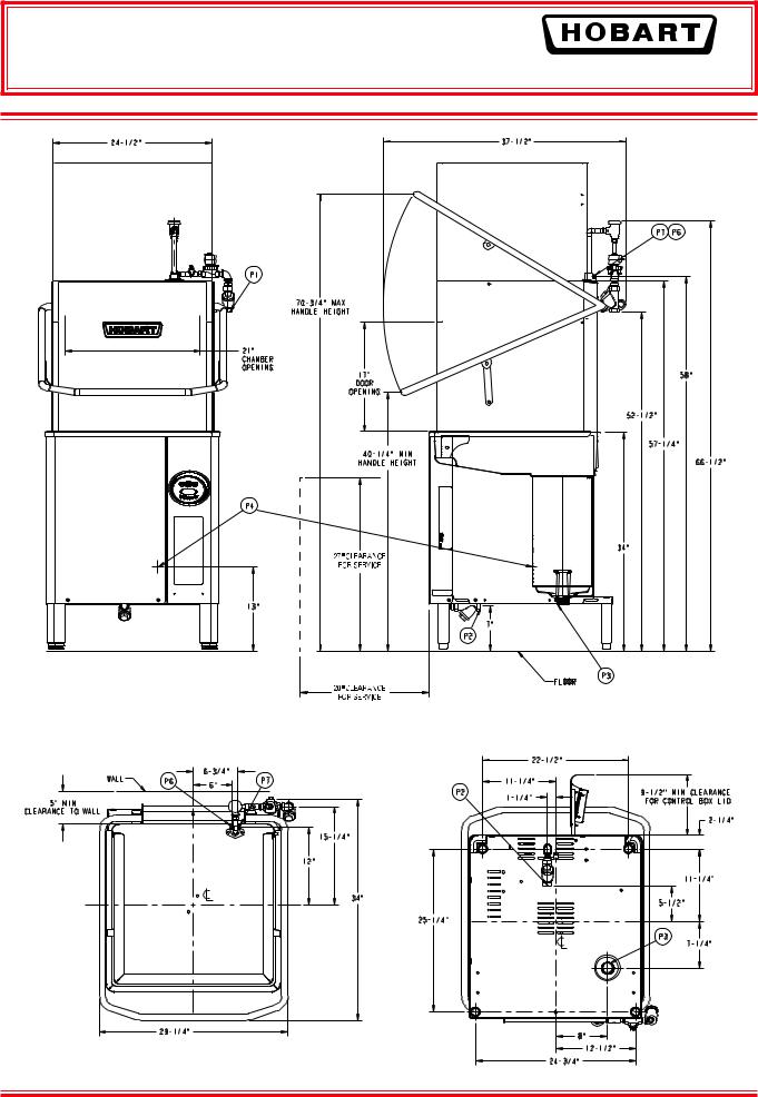
WASH: Hobart revolving stainless steel wash arms with unrestricted openings above and below provide thorough distribution of water jets to all dishware surfaces. Arms are easily removable for cleaning and are interchangeable. Stainless steel tubing manifold connects upper and lower spray system.
RINSE: Rotating rinse arms, both upper and lower, feature 14 rinse nozzles. The stainless steel upper and lower rinse arms are easily removable without tools for inspection and are interchangeable. Diaphragm-type rinse control solenoid valve mounted outside machine. Machine is equipped with special hot water vacuum breaker on downstream side of rinse valve – mounted 6" above uppermost rinse opening. Easy open brass line strainer furnished.
FILL: Microcomputer controlled fill valve installed on upstream side of rinse vacuum breaker. Ratio fill method is used giving the correct fill at any flowing water pressure. (20 PSIG minimum necessary for proper rinsing.)
DRAIN AND OVERFLOW: Large bell type automatic overflow and drain valve controlled from inside of machine. Drain automatically closed by lowering chamber. Drain seal is large diameter, high temperature “O” ring. Cover for overflow is integral part of the standpipe.
STRAINER SYSTEM: Equipped with large, exclusive self-flush- ing, easily removable perforated stainless steel, one-piece strainer and large capacity scrap basket. Submerged scrap basket minimizes frequent removal and cleaning.
HEATING EQUIPMENT: Standard tank heat is 5KW electric _immersion heating element. Regulated power infrared gas immersion tube system is optional at extra cost. A solid-state igniter board controls the gas valve and provides flame ignition. A transformer steps the control circuit voltage down to 24 volts to power the igniter board and gas valves.
Gas Heated Dishwasher: For natural gas, gas pressure (customer connection) not to exceed 7" W.C. For liquefied petroleum, gas pressure to burner (customer connection) not to exceed 11" W.C. If gas pressure is higher than 7" W.C. natural or 11" W.C. LP, a pressure regulating valve must be supplied (by others) in the gas line to the dishwasher. Water temperature regulation is controlled by thermistor sensor in combination with microcomputer controls. The tank heat and positive low water protection microcomputer circuits are automatically activated when the main power switch is turned “on”. If tank is accidentally drained, low water protection device automatically turns heat off. Gas immersion tube is additionally protected by a high limit device mounted on the surface of the tube. These features are standard with the Hobart Microcomputer Control System.
OPTIONAL EQUIPMENT AT EXTRA COST – ELECTRIC
BOOSTER HEATER: Electric booster with Sense-A-TempTM technology adequately sized to raise 110°F inlet water to 180°F (not available on gas heat machines).
ACCESSORIES: 193⁄4" x 193⁄4" peg and combination dish racks. Splash shield for corner installations. End of cycle audible alarm (field activated). Delime notification (field activated). Desirable functional accessories can be furnished at added cost. See listed options and accessories on this specification sheet. Write to the factory for special requirements not listed above.
|
As continued product improvement is a policy of Hobart, specifications are subject to change without notice. |
|
|
|
|
Page 8 of 8 |
F-40078 – AM Select Dishwasher |
F-40078 (rev. 07/09) |
AM15 Dishwasher Technical Manual Page 10 of 83Litho In U.S.A. (H-01) |
AM Select DISHWASHERS
MODELS
AM15 ML-130038
AM15F ML-130045
AM15T ML-130039
701 s. RIDGE AVENUE |
|
TROY, OHIO 45374-0001 |
|
937 332-3000 |
|
www.hobartcorp.com |
FORM 35320 Rev. C (Oct. 2009) |
|
|
AM15 Dishwasher Technical Manual Page 11 of 83 |
|
post in a prominent location the instructions to be followed in the event the smell of gas is detected. This information can be obtained from the local gas supplier.
important
in the event a gas odor is detected, shut down unit(s) at main shutoff valve and contact the local gas company or gas supplier for service.
for your safety
do not store or use gasoline or other flammable vapors or liquids in the vicinity of this or any other appliance.
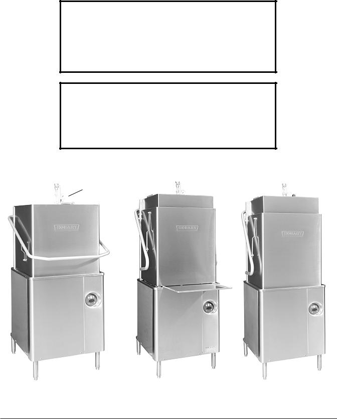
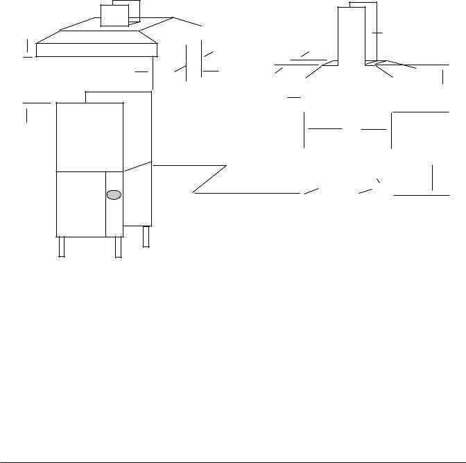
Model AM15 |
Model AM15F |
Model AM15T |
Pressure
Gauge
Fig. 1
© Hobart corporation, 2009 |
– 2 – |
AM15 Dishwasher Technical Manual Page 12 of 83

Table of Contents
GENERAL. . . . . . . . . . . . . . . . . . |
|
|
|
|
|
|
|
|
|
|
|
|
|
|
|
|
|
4 |
||
INSTALLATION. . . . . . . . . . . . . . . . |
. |
. |
|
|
|
|
|
|
|
|
|
|
|
|
|
|
|
5 |
||
UNPACKING. . . . . . . . . . . . . . . . |
. |
. |
|
|
|
|
|
|
|
|
|
|
|
|
5 |
|||||
INSTALLATION CODES . . . . . . . . . . . |
. |
. |
. . |
|
. |
|
. |
|
. |
|
|
|
|
|
|
|
5 |
|||
LOCATION . . . . . . . . . . . . . . . . |
. |
. |
|
|
|
|
|
|
|
|
|
|
5 |
|||||||
CORNER INSTALLATION . . . . . . . . . |
. |
. |
. . |
|
. |
|
. |
|
. |
|
. |
. |
|
|
|
|
6 |
|||
WATER REQUIREMENTS. . . . . . . . . . . |
. |
. |
. . |
|
. |
|
. |
|
. |
|
|
|
|
|
|
|
7 |
|||
PLUMBING CONNECTIONS . . . . . . . . . |
. |
. |
. . |
|
. |
|
. |
|
. |
|
. . |
|
|
|
|
|
8 |
|||
DRAIN CONNECTION. . . . . . . . . . |
. |
. |
. . |
|
. |
|
. |
|
. |
|
. |
|
|
|
|
|
8 |
|||
WATER CONNECTION . . . . . . . . . . |
. |
. |
. . |
|
. |
|
. |
|
. |
|
. |
|
|
|
8 |
|||||
Without Electric Booster Water Heater . . . . . . . . . . . . . . . |
. |
|
. |
|
. 8 |
|||||||||||||||
With Electric Booster Water Heater. . . . . . . . . . . . . . . . |
. |
. |
8 |
|||||||||||||||||
GAS TANK HEAT (When Specified) . . . . . . . |
. |
. |
. . |
|
. |
|
. |
|
. |
|
. |
. |
. |
. |
|
|
9 |
|||
VENTING REQUIREMENTS — WITH GAS TANK HEAT . . . . . . . . . . |
. |
|
. |
|
. 10 |
|||||||||||||||
Rate of Exhaust Flow Calculations . . . . . . . . . . . . . . . . |
. |
. |
11 |
|||||||||||||||||
ELECTRICAL CONNECTIONS . . . . . . . . . |
. |
. |
. . |
|
. |
|
. |
|
. |
|
. |
. |
|
|
|
12 |
||||
Dishwasher Without Electric Booster . . . . . . . . . . . . . . . |
. |
. |
|
. 12 |
||||||||||||||||
Check Rotation (Three Phase Machines Only) . . . . . . . . . . . . |
. |
|
. |
|
. 12 |
|||||||||||||||
Dishwasher With Electric Booster (Separately Connected). . . . . . . |
. |
. |
|
. |
13 |
|||||||||||||||
Dishwasher With Electric Booster (Single Point Electrical Connection). . . |
. |
|
. |
|
. 13 |
|||||||||||||||
EQUIPMENT CONNECTIONS . . . . . . . . . |
. |
. |
. . |
|
. |
|
. |
|
. |
|
. |
. |
|
|
|
13 |
||||
Vent Fan Control . . . . . . . . . . . |
. |
. |
. . |
|
. |
|
. |
|
. |
|
|
|
|
|
|
13 |
||||
Remote Booster Control . . . . . . . . |
. |
. |
. . |
|
. |
|
. |
|
. |
|
. |
. |
. |
|
|
|
13 |
|||
DETERGENT, RINSE AID, SANITIZER DISPENSERS – Tubing Installation. . |
. |
. |
|
. |
14 |
|||||||||||||||
Detergent Dispenser . . . . . . . . . |
. |
. |
. . |
|
. |
|
. |
|
. |
|
. |
. |
|
|
14 |
|||||
Rinse Aid Dispenser. . . . . . . . . . |
. |
. |
. . |
|
. |
|
. |
|
. |
|
. |
|
|
|
14 |
|||||
Chemical Sanitizer Dispenser . . . . . . |
. |
. |
. . |
|
. |
|
. |
|
. |
|
. |
. |
. |
. . |
|
|
14 |
|||
EQUIPMENT CONNECTIONS – Detergent, Rinse Aid, Sanitizer Dispensers. . . . |
. |
|
. |
|
. 15 |
|||||||||||||||
Detergent Dispenser . . . . . . . . . |
. |
. |
. . |
|
. |
|
. |
|
. |
|
. |
. |
|
|
15 |
|||||
Rinse Aid / Sanitizer Dispenser(s) . . . . . . . . . . . . . . . . . |
. |
|
|
15 |
||||||||||||||||
SETUP (All Models). . . . . . . . . . . . . |
. |
. |
. . |
|
. |
|
|
|
16 |
|||||||||||
Sanitizing Mode. . . . . . . . . . . |
. |
. |
. . |
|
. |
|
. |
|
. |
|
|
|
16 |
|||||||
End of Cycle Buzzer. . . . . . . . . . . . . . . . . . . . . . . . . . . . . . . . . . . . . . . . . . . |
. . |
. . |
. . 16 |
|||||||||||||||||
OPERATION . . . . . . . . . . . . . . . . . |
. |
|
|
17 |
||||||||||||||||
PREPARATION . . . . . . . . . . . . . |
. |
. |
. . |
|
. |
|
|
|
17 |
|||||||||||
DISHWASHING. . . . . . . . . . . . . |
. |
. |
. . |
|
. |
|
|
18 |
||||||||||||
CLEANING. . . . . . . . . . . . . . . |
. |
. |
. |
|
|
|
19 |
|||||||||||||
DELIME INSTRUCTIONS. . . . . . . . . |
. |
. |
. . |
|
. |
|
. |
|
. |
|
. |
. |
|
|
20 |
|||||
DOs AND DON’Ts FOR YOUR NEW HOBART WAREWASHER . . . . . . . |
. . . 20 |
|||||||||||||||||||
MAINTENANCE. . . . . . . . . . . . . . . . . . . . . . . . . . . . . . |
. . |
. . |
. . . |
. |
. |
. |
. |
. |
. |
. |
. |
. . |
. . |
. . |
. . . . |
. . |
. |
. |
. |
. 21 |
Wash Arms. . . . . . . . . . . . . |
. |
. |
. . |
|
. |
|
21 |
|||||||||||||
Motor(s). . . . . . . . . . . . . . |
. |
. |
. . |
|
21 |
|||||||||||||||
Flue (Machines Equipped With Gas Tank Heat Only). . . . . . . . . . |
. |
|
. |
|
. 21 |
|||||||||||||||
TROUBLESHOOTING. . . . . . . . . . . . . |
. |
. |
. . |
|
. |
|
|
|
22 |
|||||||||||
Manual Reset Button on Pump Motor. . . . . . . . . . . . . . . |
. |
. |
|
. 22 |
||||||||||||||||
SERVICE. . . . . . . . . . . . . . . . . . |
|
|
24 |
|||||||||||||||||
– 3 –
AM15 Dishwasher Technical Manual Page 13 of 83

Installation, Operation, and Care of
AM Select DISHWASHERS
SAVE THESE INSTRUCTIONS
GENERAL
Models AM15 and AM15T dishwashers can be configured for straight through or corner operation. Model AM15F is configured for front loading. AM15 and AM15T dishwashers are shipped from the factory in straight-through configuration. Straight-through machines can easily be converted to corner operation. Model AM15F includes a front-loader shelf and leftand right-side shields as standard equipment. The front-loader shelf on AM15F can be positioned up (inside the machine during operation) or down (outside the machine during operation).
AM15, AM15F and AM15T dishwashers are designed to operate in one of two modes: Hot water sanitizing mode (designated by the letters “AH” or “AP” on the display when the machine is turned on), or a chemical sanitizing mode (designated by the letters “AC” on the display when the machine is turned on).
The serial number can be found on the machine data plate located on the bottom of the front panel.
DO NOT attempt to operate this dishwasher in the chemical sanitizing mode without a properly installed, NSF-certified, chemical sanitizer feeder (not supplied with machine). Contact an authorized detergent representative for information about a chemical sanitizer feeder.
The pump motor is rated 2 H.P. and has thermal overload protection.
The fill line incorporates an atmospheric vacuum breaker to prevent any reverse flow of water from the dishwasher into the potable water supply.
The unit, once turned on, will fill the wash tank to the appropriate level and automatically stop filling once the level is reached.
A float, located in the wash tank, will shut off the heat supply if the water level becomes too low. When the water returns to a proper level, the heating circuit is again operational.
A frame-mounted 8.5 KW electric booster water heater is available as an option on machines equipped with electric tank heat. The booster water heater is designed to maintain a minimum final rinse temperature of 180°F provided the incoming water to the booster heater is at least 110°F.
High-temperature or gas heat dishwashers will probably require a hood or vent over the dishwasher in order to meet local codes. Low-temperature chemical sanitizing machines or low usage electric heat dishwashers may not require individual venting of the machine if the room is amply exhausted. Refer to pages 10 and 11 for venting and hood requirements. Verify with local codes for final authority.
– 4 –
AM15 Dishwasher Technical Manual Page 14 of 83
INSTALLATION
UNPACKING
Immediately after unpacking the dishwasher, check for possible shipping damage. If this machine is found to be damaged, save the packaging material and contact the carrier within 15 days of delivery.
Prior to installation, test the electrical service to make sure it agrees with the specifications on the machine data plate; this includes the optional electric booster, if equipped. The dishwasher data plate is located at the bottom of the front panel.
INSTALLATION CODES
Installation must be in accordance with state and local codes, or in the absence of local codes, with the National Fuel Gas Code, ANSI Z223.1 (latest edition) if applicable, and the National Electrical Code ANSI/NFPA 70 (latest edition). In Canada, the installation standards are: CAN/CGA B149.1, CAN/CGA B149.2, and CSA C22.2 No.1 (latest editions).
LOCATION
Before finalizing the location, make sure that consideration has been given for the electrical conduit, water supply, drain connection, gas supply and venting (if applicable), tabling (if needed), chemical feeder replenishment (if applicable) and adequate clearance for opening the door.
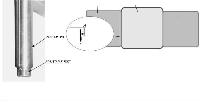
The dishwasher must be level before any connections are made. Turn the threaded feet (Fig. 2) as required to level the machine and adjust to the desired height.
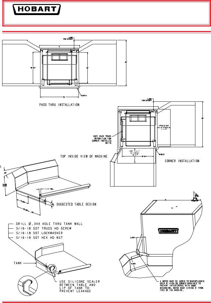
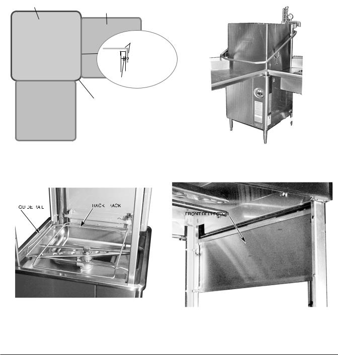
The edge of dish table that overhangs the AM15 wash tank should be turned down and fitted over the top of the dishwasher tank (Fig. 3). Apply an NSF approved sealant between the overhang of the dish table and the inner wall of the wash tank to prevent leakage (Fig. 3). Fasten the dish tables to the inner wall of the wash tank with non-rusting truss head screws or rivets (Fig. 3).
For straight-through installations, clearance at the front and 15 inches out from the dishwasher at the right side by 27 inches above the finished floor must be provided for servicing.
DISH TABLE |
WASH TANK |
DISH TABLE
DISH TABLE
MACHINE SCREW

 OR RIVET
 SEALANT
 INNER WALL OF
WASH TANK
NUT
STRAIGHT-THROUGH OPERATION SHOWN
Fig. 3
Fig. 2
– 5 –
AM15 Dishwasher Technical Manual Page 15 of 83
CORNER INSTALLATION
Before placing the dishwasher in its operating location, check machine configuration. If the machine is being installed in a corner (Figs. 4, 5), clearances of 20 inches out from the dishwasher under the left-hand tabling by 27 inches above the finished floor and 15 inches out from the dishwasher at the right side by 27 inches above the finished floor must be provided for servicing. For proper installation of a corner machine, the control and display should be positioned at the front corner for operator access (Fig. 5).
For corner installation, rotate the rack track so the guide rail is positioned on the left side (Fig. 6). For corner machines, remove the front door deflector (unscrew three bolts / nuts, Fig. 7).
WASH TANK
DISH TABLE
DISH TABLE
MACHINE SCREW

 OR RIVET
 SEALANT
 INNER WALL OF
WASH TANK
NUT
CONTROLS MUST BE ACCESSIBLE AT
FRONT CORNER.
 DISH TABLE
CORNER OPERATION SHOWN
|
|
|
Fig. 4 |
|
|
Fig. 5 |
|
|
|
|
|
|
|
|
|
|
|
|
|
|
|
|
|
|
|
|
|
|
|
|
|
|
|
|
|
|
|
|
|
|
|
|
|
|
|
|
|
|
|
|
|
|
|
|
|
Fig. 6 |
Fig. 7 |
– 6 –
AM15 Dishwasher Technical Manual Page 16 of 83
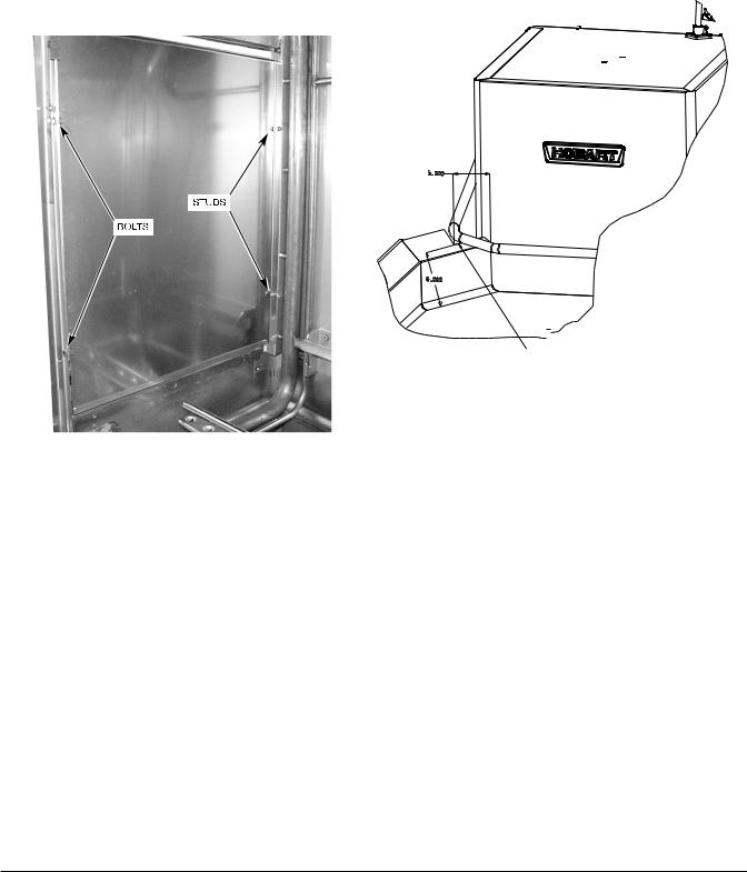
A splash shield is available (at extra cost) for corner installations to cover the left side opening to the wall. Install the splash shield on the left side using the two 1⁄4-20 studs on the left rear corner with a lockwasher and nut for each (Fig. 8) and using the two 1⁄4-20 bolts, lockwashers and nuts on the left front corner (fasteners are provided in the kit).
For corner installations, tabling with backsplashes over 6" high require that a notch be provided to prevent interference with the door mechanism (Fig. 9).
|
A notch must be added to backsplashes |
|
over 6" high on corner machines to |
|
prevent interference with door |
|
mechanism. Notch must extend 5" from |
|
face of the machine. |
Fig. 8 |
Fig. 9 |
WATER REQUIREMENTS
Proper water quality can improve warewashing performance by reducing spotting, lowering chemical supply costs, improving productivity and extending equipment life. Local water conditions vary from one location to another. The recommended proper water treatment for effective and efficient use of this equipment will also vary depending on the local water conditions. Ask your municipal water supplier for details about local water specifics prior to installation.
Recommended water hardness is 3 grains of hardness per gallon or less. Chlorides must not exceed 50 parts per million. Water hardness above 3 grains per gallon should be treated by a water conditioner (water softener or in-line treatment). Water treatment has been shown to reduce costs associated with machine cleaning, reduce the need for deliming the dishwasher and reduce detergent usage.
Sediment, silica, chlorides or other dissolved solids may lead to a recommendation for particulate filtration or reverse osmosis treatment.
If an inspection of the dishwasher or booster heater reveals lime build-up after the equipment has been in service, in-line water treatment should be considered, and, if recommended, should be installed and used as directed. Contact your Hobart Service office for specific recommendations.
– 7 –
AM15 Dishwasher Technical Manual Page 17 of 83

PLUMBING CONNECTIONS
WARNING: PLUMBING CONNECTIONS MUST COMPLY WITH APPLICABLE SANITARY, SAFETY AND PLUMBING CODES.
DRAIN CONNECTION |
|
The drain connection is a 11⁄2" externally threaded pipe connected |
|
straight down from the bottom of the wash tank (Fig. 10). The |
|
connection can be made in any direction by using the proper fitting |
|
(not supplied) and routing to the appropriate drain line. |
|
If a grease trap is required by code, it should have a minimum flow |
Fig. 10 |
capacity of 38 gallons per minute. |
|
WATER CONNECTION |
|
A suitable water hammer arrestor should be installed in the water line just ahead of the dishwasher.
Without Electric Booster Water Heater
The water supply line is connected to the line strainer (top rear, Fig. 1) with 3⁄4" pipe. A manual shutoff valve and pipe union are required (not supplied).
Required Incoming Water Temperature
Model |
Sanitizing Mode |
Water Supply |
||
Minimum Temperature |
Recommended Temperature |
|||
|
|
|||
Without Built-in Booster |
Hot Water Sanitizing |
180°F (82°C) |
180°F (82°C) |
|
|
|
|
|
|
Without Built-in Booster |
Chemical Sanitizing |
120°F (49°C) |
140°F (60°C) |
|
|
|
|
|
|
With Built-in Booster |
Hot Water Sanitizing |
110°F (43°C) |
140°F (60°C) |
|
|
|
|
|
|
Proper dishwasher operation requires a flowing pressure of 20 ± 5 psig at the dishwasher. If the flowing pressure exceeds 25 psig, a pressure reducing valve (not supplied) must be installed in the water supply line. CAUTION: The water pressure regulator must have a relief by-pass. Failure to use the proper type of pressure regulator may result in damage to the unit.
A pressure gauge (Fig. 1) is provided (not installed) for verification of proper water pressure. The water pressure is monitored when the solenoid valve is open and water is flowing.
With Electric Booster Water Heater
The water supply line is connected below the booster with the line strainer (supplied) and 3⁄4" pipe. A manual shut off valve and pipe union are required (not supplied).
The water supply should have a minimum temperature of 110°F, and a flowing pressure of 20 ± 5 psig at the pressure gauge on top of the machine. If the flowing pressure exceeds 25 psig, a pressure reducing valve (not supplied) must be installed in the water supply line. CAUTION: The water pressure regulator must have a relief by-pass. Failure to use the proper type of pressure regulator may result in damage to the unit.
Incoming water temperature below 110°F may require longer wash cycle time than the 57 second cycle; refer to operation, pages 17 – 18.
When the fill / final rinse valve is on, water from the booster tank enters the dishwasher through the final rinse arms. During the rinse cycle, this water is 180°F. A small amount of water will likely dribble out of the lower rinse arm into the tank between cycles due to the natural expansion of water as it is being heated.
– 8 –
AM15 Dishwasher Technical Manual Page 18 of 83
GAS TANK HEAT (When Specified)
Check the gas data plate attached to the dishwasher or the tag attached to the incoming gas piping for the type of gas to be used.
The burner is not adjustable. The maximum flowing inlet gas pressure must not exceed the Maximum value in the table. If line pressure exceeds the Maximum value in the table, an additional pressure regulator (not supplied) must be installed in the supply line.
Type |
|
Inches W.C. (Water Column) FLOWING |
||
of |
BTU/HR |
Incoming Line Pressure |
Manifold |
|
Gas |
|
Minimum |
Maximum |
Pressure |
|
|
|
|
|
Natural |
25,000 |
3.5 |
7.0 |
3.2 |
Propane |
25,000 |
9.0 |
11.0 |
8.2 |
Static inlet line pressure should not exceed 14" W.C. The minimum value is for input adjustment.
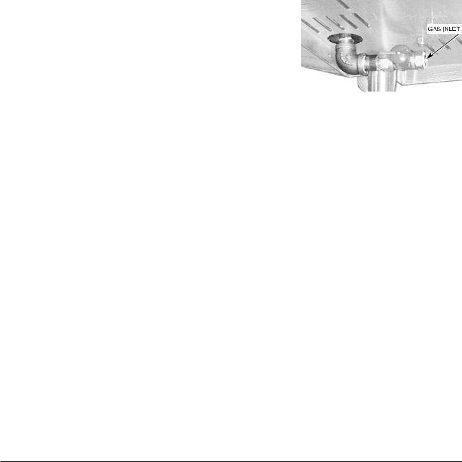
The gas valve is provided with a pressure tap to measure the gas pressure downstream, which is also the manifold pressure. Gas supply piping must have a sediment trap (supplied by others) installed ahead of the dishwasher’s gas control. Connect the gas supply to the 1⁄2" NPT gas inlet underneath the machine (Fig. 11).
NOTE: DO NOT use Teflon tape on gas line pipe threads. For |
|
gas line pipe connections, use Loctite 565, Hobart part 546292, |
|
or a flexible sealant suitable for use with Natural and Propane |
|
Gases. |
Fig. 11 |
The appliance and its gas connections must be leak tested before placing the appliance in operation. Use soapy water for leak test. DO NOT use open flame. The installation must conform with local codes, or in the absence of local codes, with the National Fuel Gas Code, ANSI Z223.1 (latest edition). Copies may be obtained from American Gas Association, Inc., 1515 Wilson Boulevard, Arlington, VA 22209.
The appliance and its individual shutoff valve must be disconnected from the gas supply piping system during any pressure testing of that system at test pressures in excess of 1⁄2 psig (3.45kPa).
The appliance must be isolated from the gas supply piping system by closing its individual manual shutoff valve during any pressure testing of the gas supply piping system at test pressures equal to or less than 1⁄2 psig (3.45kPa).
Dissipate test pressure from the gas supply line before re-connecting the appliance and its manual shutoff valve to the gas supply line. Caution: Failure to follow this procedure may damage the gas valve.
The dishwasher must be installed so that the flow of combustion and ventilation air will not be obstructed. Do not store material underneath the machine; air openings into the combustion chamber must not be blocked. Make sure there is an adequate supply of make-up air in the room to allow for combustion of the gas at the burner.
Keep the appliance area free and clear from all combustible substances. Do not obstruct the flow of combustion and ventilation air. The dishwasher must have a minimum clearance from combustible construction of 1 inch from the flue at the rear. Clearances of 20 inches out from the dishwasher at the front (or left side in a corner installation) by 27 inches above the finished floor and 15 inches out from the dishwasher at the right side by 27 inches above the finished floor must be provided for servicing.
The burner is ignited automatically by solid state electronic circuitry; there is no pilot light. Gas flow is regulated by the temperature control circuit.
– 9 –
AM15 Dishwasher Technical Manual Page 19 of 83
VENTING REQUIREMENTS — WITH GAS TANK HEAT
Hobart model AM15, AM15F or AM15T dishwashers equipped for gas tank heat are not provided with a flue collar and are not intended to have the flue directly connected to a ventilation system. However, the products of combustion must be vented to the outside air. The most common method of venting is a vent hood over the entire dishwasher (Fig. 12). Refer to Rate of Exhaust Flow Calculations on the next page for calculations of the proper vent rate for your hood. Another method is a small vent hood (Fig. 13) positioned about five inches above the flue exit at the rear of the dishwasher and connected to existing ductwork. In either case, an electrical interlock must be installed to allow the flow of gas to the dishwasher burner ONLY when the exhaust system is energized. For additional information, refer to the National Fuel Gas Code, ANSI Z223.1, NFPA 54.
• IMPORTANT: Make sure the installation meets the local code for your area.
1' TO 4' CLEARANCE
|
|
|
31⁄2" |
|
|
|
|
|
3" x 3" DUCT INTO CURRENT SYSTEM
6" |
|
|
|
|
|
|
|
|
|
4" |
|||
MINIMUM |
MINI VENT HOOD |
|
|
|
|
|
|
|
|
||||
|
|
|
|
|
|
|
|
|
|
|
|
||
OVERHANG |
|
|
|
|
|
|
|
|
|
|
|
||
|
|
|
|
|
|
|
|
|
|
|
|
|
|
ON ALL SIDES |
|
|
|
|
|
|
|
|
|
|
|
|
|
|
|
|
|
|
|
|
|
|
|
|
|||
18" OVERHANG |
|
|
|
6" |
|
|
|
||||||
RECOMMENDED |
|
|
|
|
|
|
|
|
|
|
|
|
|
OVER LOADING OR |
|
|
|
|
|
|
|
|
|
5" GAP |
|||
UNLOADING DOORS |
|
|
|
|
|
|
|
|
|
MINIMUM |
|||
|
|
|
|
|
|
|
|
|
|
|
|||
|
|
DISHWASHER FLUE EXIT |
|
|
|
|
|
|
|||||
|
|
|
|
|
|
|
|
|
|
|
|
|
|
|
|
|
|
|
|
|
|
|
|
|
|
||
|
|
|
|
|
|
|
|
|
|
|
|||
|
|
|
|
|
|
|
|
|
|
|
|
|
|
Fig. 12 |
Fig. 13 |
– 10 –
AM15 Dishwasher Technical Manual Page 20 of 83
NOTE: Any listed and labeled factory-built commercial exhaust hood tested in accordance with UL Standard 710 by a nationally recognized testing laboratory, should be installed according to the terms of its listing and the manufacturer’s installation instructions.
CLEARANCE
HEIGHT
LENGTH

WIDTH
RATE OF EXHAUST FLOW CALCULATIONS
Based on the 1996 International Mechanical Code.
The Rate of air flow required for a vent hood is calculated using the following definitions (Fig. 14):
Q = Rate of Air Flow in Cubic Feet Per Minute or [ CFM ] Required for the Hood.
A = Area of Hood Opening in Feet2 = (L x W)
D = Clearance Height = Distance in Feet from lower lip of hood to top of dishwasher chamber.
P = Perimeter of Hood that is Open. This depends on the hood design, as follows:
Fig. 14
Perimeter Calculation Formula
Hood Design |
Corner |
Wall |
Island |
Number of Open Sides |
2 Sides Open |
3 Sides Open |
4 Sides Open |
P = |
L + W |
L + W + W |
L + L + W + W |
Dimensions |
Feet |
Feet |
Feet |
If there are four open sides (Island Design), the calculation of the Rate is as follows: Q = 75 x A
If there are three or fewer open sides, the calculation of the Rate is as follows: Q = 50 x A
As an alternate method, the Rate can be calculated as follows: Q = 50 x P x D
Example: |
|
|
|
|
|
|
L = 3 |
W = 3 |
D = 2 |
|
|
|
|
|
|
|
|
Rate Calculations |
|
|
|
|
|
|
|
|
|
|
|
Hood Design |
Corner |
Wall |
Island |
|
|
|
Number of Open Sides |
2 Sides Open |
3 Sides Open |
4 Sides Open |
|
|
|
Q = 75 x A |
|
|
|
675 CFM |
|
|
Q = 50 x A |
|
450 CFM |
450 CFM |
|
|
|
Q = 50 x P x D |
600 CFM |
900 CFM |
1200 CFM |
|
– 11 –
AM15 Dishwasher Technical Manual Page 21 of 83
ELECTRICAL CONNECTIONS
WARNING: ELECTRICAL AND GROUNDING CONNECTIONS MUST COMPLY WITH THE APPLICABLE PORTIONS OF THE NATIONAL ELECTRICAL CODE AND/OR OTHER LOCAL ELECTRICAL CODES.
WARNING: DISCONNECT THE ELECTRICAL POWER TO THE MACHINE (BOTH DISHWASHER AND BOOSTER IF APPLICABLE) AND FOLLOW LOCKOUT / TAGOUT PROCEDURES.
Refer to the wiring diagram attached inside the front trim panel and to the machine data plate for service size requirements when connecting the dishwasher. Also, refer to Electrical Data, page 12.
To access the controls area, remove the right side panel, remove the front panel and open the control panel door. The dishwasher electrical service connection can be made through the 13⁄32" diameter hole for 3⁄4 inch trade size conduit located on the right side at the rear of the machine. By removing a knockout, this hole can be enlarged to 13⁄8" diameter for 1 inch trade size conduit, if required.
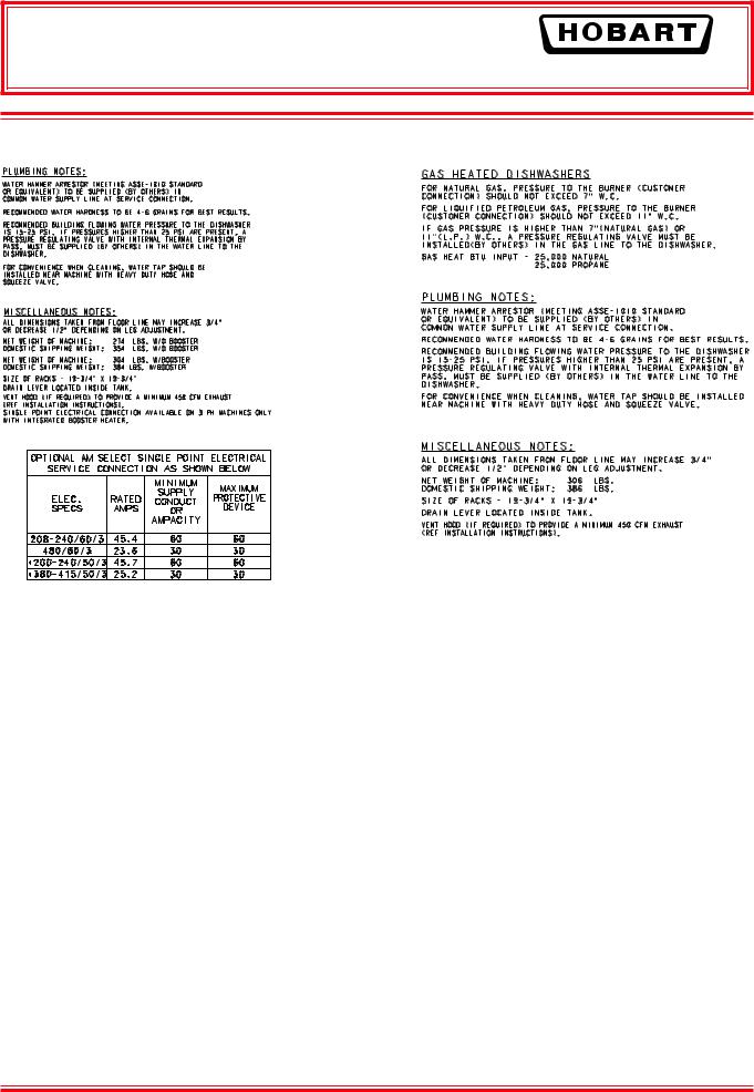
ELECTRICAL DATA
|
|
|
|
Minimum Circuit Ampacity |
||
|
|
|
|
Maximum Protective Device |
||
|
|
|
|
|
AMPS |
|
|
|
|
|
|
|
|
Models |
Volts / Hz / Ph |
Tank Heat |
|
Optional 8.5 KW Electric Booster |
||
|
|
|
|
|||
Dishwasher |
8.5 KW |
|
Optional Single Point |
|||
|
|
|
|
|||
|
|
|
|
Electrical Connection |
||
|
|
|
ONLY |
Booster |
|
|
|
|
|
|
3 Phase Only |
||
|
|
|
|
ONLY |
|
|
|
|
|
|
|
Dishwasher and Booster |
|
|
|
|
|
|
|
|
|
208 - 240 / 60 / 1 |
Electric |
50 |
50 |
|
|
|
Gas |
20 |
|
|
|
|
|
|
|
|
|
||
AM15 |
208 - 240 / 60 / 3 |
Electric |
30 |
30 |
|
60 |
Gas |
15 |
|
|
|
||
AM15F |
|
|
|
|
||
|
Electric |
15 |
15 |
|
30 |
|
AM15T |
480 / 60 / 3 |
|
||||
Gas |
15 |
|
|
|
||
|
|
|
|
|
||
|
200 - 240 / 50 / 3 |
Electric |
30 |
30 |
|
60 |
|
380 - 415 / 50 / 3 |
Electric |
15 |
15 |
|
30 |
Compiled in accordance with the national electrical code, NFPA 70 (latest edition).
A fused disconnect switch or circuit breaker (not supplied) must be installed in the electrical service line(s) supplying this dishwasher and should meet the requirements of your local electrical code.
Dishwasher Without Electric Booster
For single-phase machines, power supply connections are made to terminal blocks. For three-phase machines connections are made to contactor lugs. The machine must be grounded according to electrical code(s); a grounding lug is provided in the controls area. Electrical connections for machines with gas tank heat are made to contactor 1CON in the controls area.
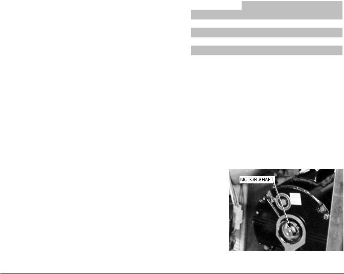
Check Rotation (Three-Phase Machines Only)
Three-phase motors must rotate in the direction of the arrow on the pump housing. In order to check rotation, remove the bearing cap to observe the motor shaft (Fig. 15). Close the machine doors and press the power switch to ON. When the machine is completely filled, open and close machine doors to verify that the motor shaft rotates in the clockwise direction.
If the rotation is incorrect, DISCONNECT ELECTRICAL POWER SUPPLY and interchange any two of the incoming power supply
leads. Reconnect the power supply and verify correct rotation. Fig. 15 Replace the motor bearing cap.
– 12 –
AM15 Dishwasher Technical Manual Page 22 of 83
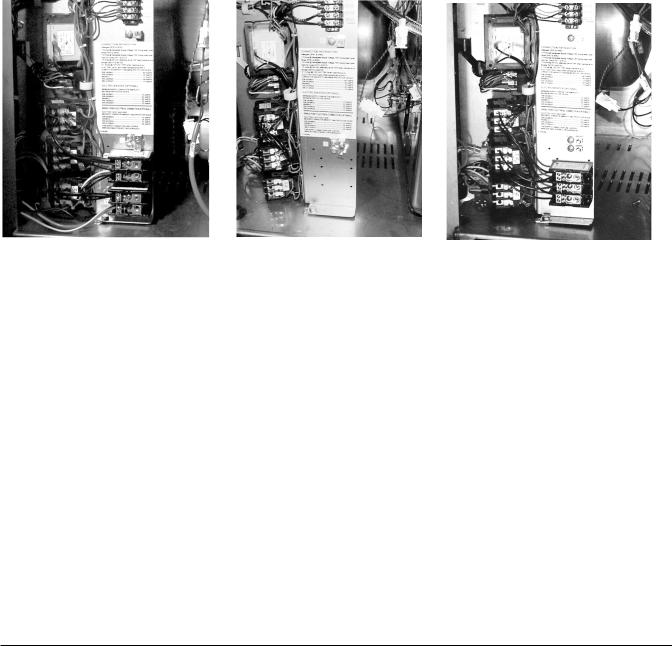
Dishwasher With Electric Booster (Separately Connected)
Single phase machines with an electric booster require two separate connections, one for the booster and the other for the dishwasher (including motor, controls and tank heat). For single-phase machines, all power supply connections are made to terminal blocks (Fig. 16). The single phase dishwasher is connected to terminal block 1TB in the controls area. The single phase booster is connected to terminal block 2TB in the controls area.
If the machine is three phase, the electrical connection for the dishwasher is made to the contactor 2CON in the controls area. The electrical connection for the three phase booster is made to the contactor 3CON in the controls area (Fig. 17).
Dishwasher With Electric Booster (Single Point Electrical Connection)
Three phase machines configured with the optional single point electrical connection are connected to terminal block 1TB in the controls area (Fig. 18). The machine must be grounded according to electrical code(s); a grounding lug is provided.
Fig. 16 |
Fig. 17 |
Fig. 18 |
EQUIPMENT CONNECTIONS
WARNING: ELECTRICAL AND GROUNDING CONNECTIONS MUST COMPLY WITH THE APPLICABLE PORTIONS OF THE NATIONAL ELECTRICAL CODE AND/OR OTHER LOCAL ELECTRICAL CODES.
WARNING: DISCONNECT THE ELECTRICAL POWER TO THE MACHINE (BOTH DISHWASHER AND BOOSTER IF APPLICABLE) AND FOLLOW LOCKOUT / TAGOUT PROCEDURES.
Vent Fan Control
The vent fan control feature is standard on all machines. The vent fan control relay provides switch contacts only and does not provide power to the vent fan motor. The rating for a vent fan control relay connected to terminals VFC1 and VFC2 is 1.5 Amps at 240 Volts maximum. When the dishwasher is connected to the vent fan, the vent fan is switched on when the dishwasher is on, and off when the dishwasher is off.
Remote Booster Control
The booster control feature is standard on all machines. The load rating for remote booster control connections to BSTR1 and BSTR2 is 0.1 Amp. at 120 Volts maximum. The booster control provides a control signal only and does not provide power to the remote booster. When a remote booster is connected to the dishwasher, the booster is on when the dishwasher is on and off when the dishwasher is off.
– 13 –
AM15 Dishwasher Technical Manual Page 23 of 83

DETERGENT, RINSE AID, SANITIZER DISPENSERS — Tubing Installation
Detergent, rinse aid and / or sanitizer dispensers (not provided by Hobart) must have all connections sealed against leakage.
The dishwasher uses 0.74 gallons of rinse water per rack at a flow rate of 4.4 gallons per minute at 20 psig flowing pressure (equivalent to a maximum head pressure of 46 feet of water). This information is used when setting the detergent, rinse aid or sanitizer pumps.
Detergent Dispenser
The dishwasher has two 7⁄8" diameter plugged holes, one on the rear of the chamber and one on the lower part of the tank near the pump (Fig. 19). With the tank empty, remove both plugs to install the detergent dispenser.
• The chamber hole is for installation of the detergent feeder tube.
• The lower tank hole is used for installation of the detergent sensor.
Rinse Aid Dispenser
The rinse line flange connector on top of the dishwasher has two 1⁄8" NPT pipe plugs (Fig. 20).
• Remove the plug(s) (Fig. 20) for installation of the rinse aid dispenser tube and / or chemical sanitizer tube, as needed.
Chemical Sanitizer Dispenser
When the dishwasher is to be operated in the chemical sanitizing mode, the machine must be converted to low-temperature sanitization (refer to Setup, page 16). A chemical sanitizer dispenser that has been tested and certified by NSF International must be installed.
• |
Remove the pipe plug (Fig. 20) for installation |
|
of the chemical sanitizer tube. To assure an |
|
unobstructed flow of sanitizer, locate the |
|
sanitizer tube in the center of water flow by |
|
drilling the sanitizer tube fitting so that its inside |
|
diameter is equal to the outside diameter of the |
|
tube. Slide the tube into the flange until it |
|
touches the opposite side and then pull it back |
|
out 1⁄4 inch (Fig. 21). |
• |
Rate for 6% Sodium hypochlorite (bleach) — |
|
3 ml. within 10 seconds (maximum). |
• |
Rate for 8.4% Sodium hypochlorite (bleach) — |
|
2 ml. within 10 seconds (maximum). |
DETERGENT SENSOR PORT
Fig. 19
PIPE PLUGS
Fig. 20
Fig. 21
– 14 –
AM15 Dishwasher Technical Manual Page 24 of 83
Equipment Connections — Detergent, Rinse Aid, Sanitizer Dispensers
WARNING: ELECTRICAL AND GROUNDING CONNECTIONS MUST COMPLY WITH THE APPLICABLE PORTIONS OF THE NATIONAL ELECTRICAL CODE AND/OR OTHER LOCAL ELECTRICAL CODES.
WARNING: DISCONNECT THE ELECTRICAL POWER TO THE MACHINE (BOTH DISHWASHER AND BOOSTER IF APPLICABLE) AND FOLLOW LOCKOUT / TAGOUT PROCEDURES.
This machine must be operated with an automatic detergent feeder and, if applicable, an automatic chemical sanitizer feeder, including a visual means to verify that detergents and sanitizers are delivered or a visual or audible alarm to signal if detergents and sanitizers are not available for delivery to the respective washing and sanitizing systems. Refer to the installation section of this manual and to the chemical feeder equipment manual(s).
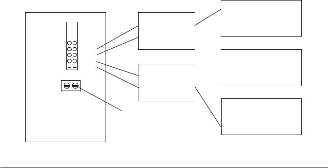
Detergent Dispenser (Fig. 22)
Terminals DPS1 and DPS2 are supplied with controlled machine line voltage. They are ON during the wash cycle and OFF between cycles or when the machine power supply is OFF. Maximum rating for detergent dispenser connected to DPS1 and DPS2 is 1.5 Amps at line voltage. Check the machine supply voltage and use corresponding feeder transformer voltage. Use UL listed 600 volt minimum insulated wire for the connections. Do not use bell wire, lamp cord or similar type wire. Splice connections, if required, must be made in the feeder transformer junction box — not in the main controls enclosure. Remove 7⁄8" diameter cap plug(s) for 1⁄2" trade size conduit fittings from the rear of the enclosure. Remove the side panel. Strain relief fittings must be provided for all wiring.
Rinse Aid / Sanitizer Dispenser(s) (Fig. 22)
Terminals RPS1 and RPS2 are supplied with controlled machine line voltage and are ON during the rinse cycle only. Maximum rating for rinse aid dispenser connected to RPS1 and RPS2 is 1.5 Amps at line voltage. Check the machine supply voltage and use corresponding feeder transformer voltage. Use UL listed 600 volt minimum insulated wire for the connections. Do not use bell wire, lamp cord or similar type wire. Splice connections, if required, must be made in the feeder transformer junction box (supplied by others) — not in the main controls enslosure. Remove 7⁄8" diameter cap plug(s) for 1⁄2" trade size conduit fittings from the rear of the enclosure. Strain relief fittings must be provided for all wiring.
 — VFC1
 — VFC2
 — BSTR1
 — BSTR2
 — DPS1
 — DPS2
 — RPS1
  — RPS2
RIGHT SIDE OF
CONTROL AREA
TRANSFORMER
PRIMARY
TRANSFORMER
PRIMARY
GROUND LUG
SECONDARY SECONDARY

DETERGENT DISPENSER
RINSE AGENT DISPENSER
CHEMICAL SANITIZER DISPENSER
Fig. 22
– 15 –
AM15 Dishwasher Technical Manual Page 25 of 83
 Loading...