How it Works
Log In / Sign Up
0
My Files
0
My Downloads
329057
History
Account Settings
Log Out
Buy Points
How it Works
FAQ
Contact Us
Questions and Suggestions
Users
Hobart
Loading...
A
AM15T-2
AM15VL
2
AM15VLT
AMERI3
2
amxhl-10a
AWS-1BWLR
AWS-1LR
AWS-2RL
B
Beta-Mig 200
BL-20
C
C-100T
C44
C-44A
2
C44A ML-104047
C44AW
3
c54
C64A
2
C88A
2
CCS110A
CE10FD
2
CE6HD
CG20
CG24
CG57
CG58
CG SERIES
CK45
CK91
CL44e
3
CL44E ML-138101
CL44eNER
CL44eR
2
CL64e
CL64eR
2
CLA2-1
2
CLCS66e
CLCS76e
CLCS86e
CLe
CLe Steam Blower-Dryer
C-LINE-A
CLPS66e
2
CLPS66E ML-138103
CLPS66E ML-138104
CLPS66eR
CLPS76e
CLPS76eR
CLPS76ER ML-138258
CLPS86e
CLPS86E ML-138176
CLPS86eR
CN401
CN50
CN85K
CN86
CN863
CN90
CN95 ML-43436
CPW100
2
CPW100A
CPW117
CPW80
CPW80AW
CPW90
CR-40
CR401
CRO-1G
CRO-E
CRS110A
CRS66
CRS-76
CUS48
CYBER FLEX 652
D
D-300
2
D300 ML-134258
D340
2
DA2
DDU38e
2
DDUe
DE1
DGC1
DGC5X
DRO2E
DRO2G
DRO2GH
3
DWT-AM15
DWT-CLe
DX50
E
EDGE
EDGE-12
3
EDGE13-11
2
EL20-2142
EL5-1124
EL5-1224UC
EPCP
EPCP-5HTi
2
EPP-1
ES5
ES600
ET-20
2
Loading...
Loading...
Nothing found
CLPS86eR
Installation Manual
20 pgs
4.24 Mb
1
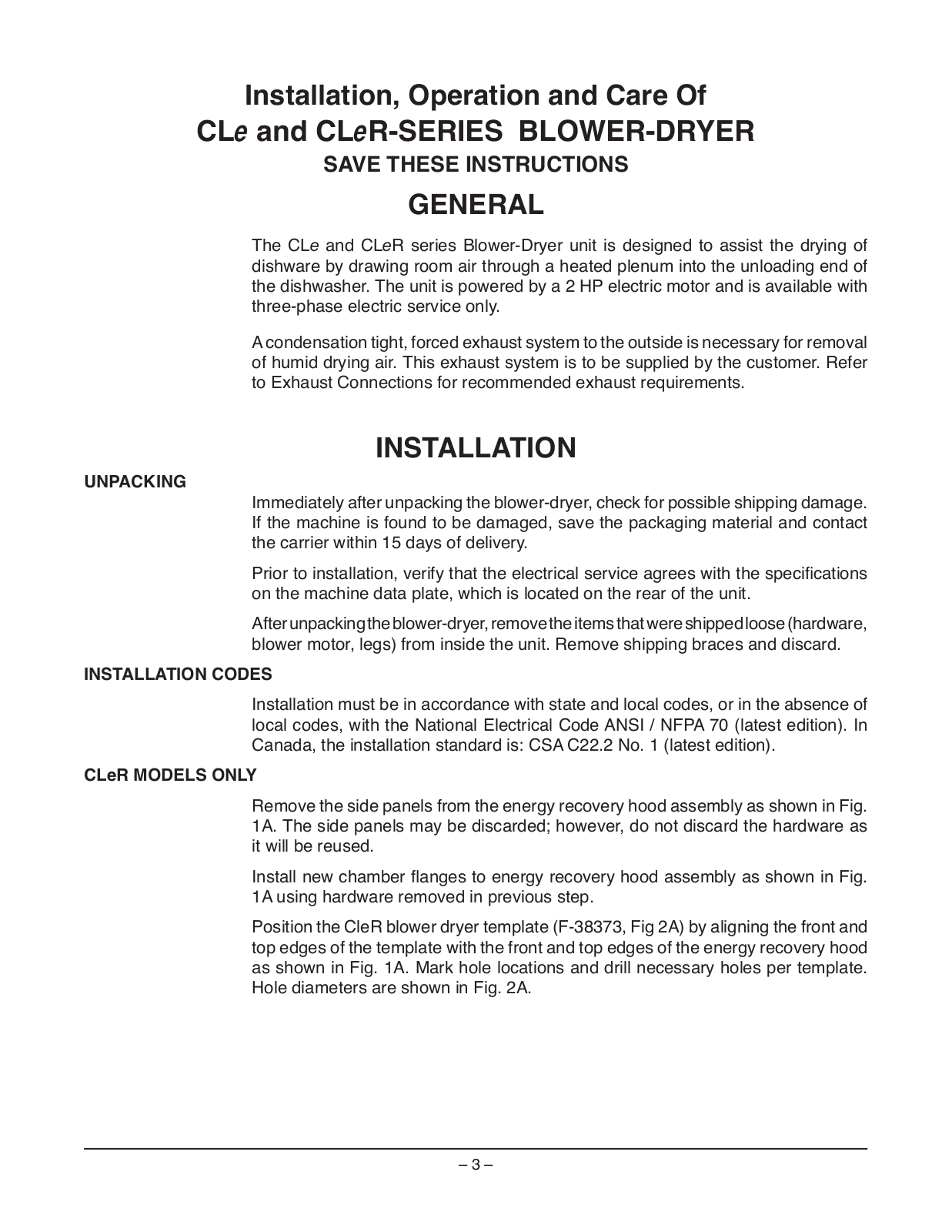
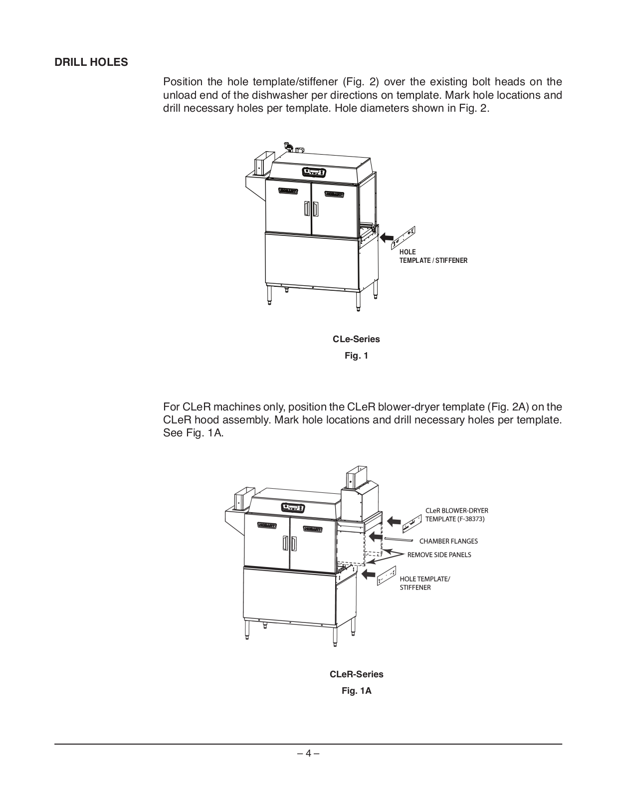
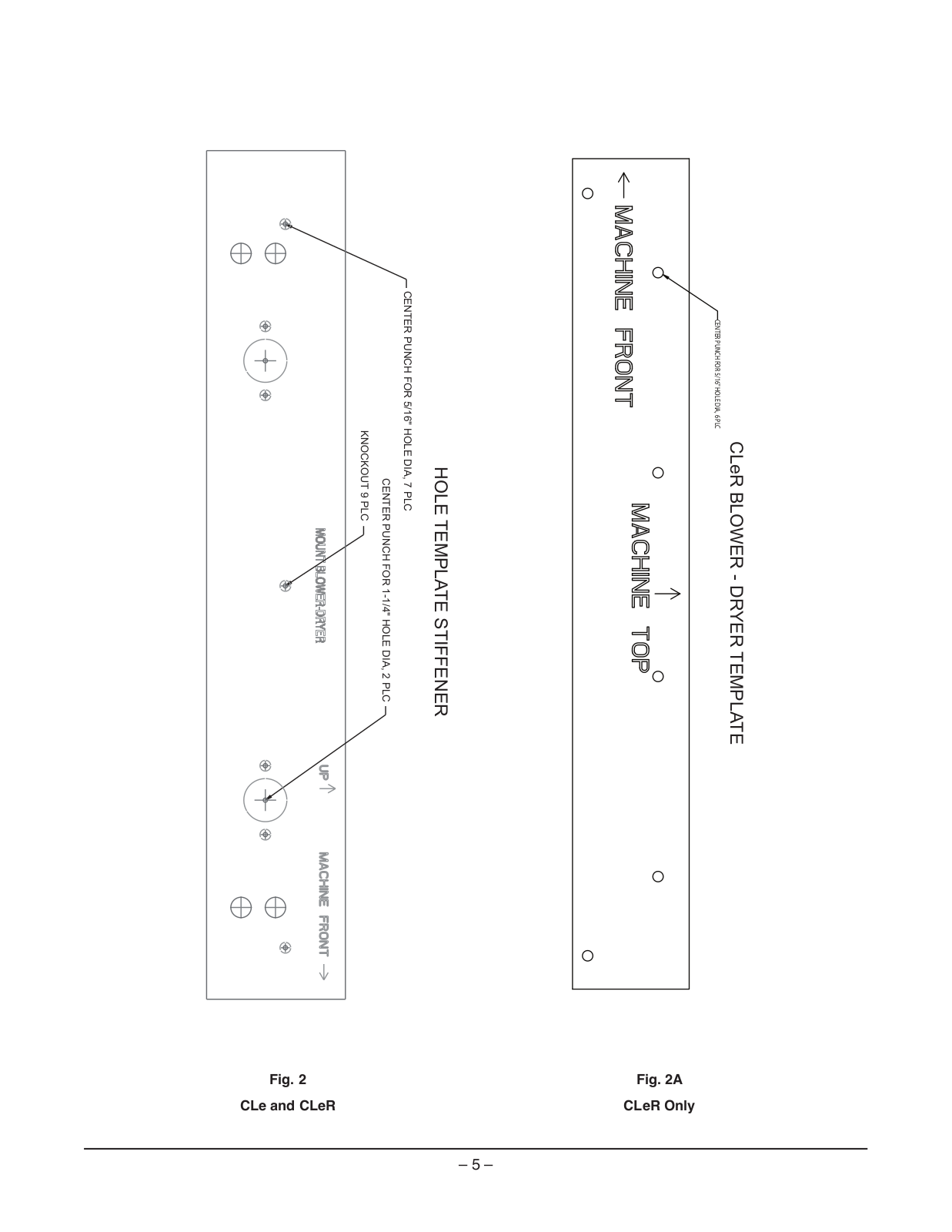
Table of contents
Loading...
Hobart CLPS86eR Installation Manual
...
Hobart Installation Manual
Download
Loading...
+
14
hidden pages
Unhide
You need points to download manuals.
1 point = 1 manual.
You can buy points or you can get point for every manual you upload.
Buy points
Upload your manuals
 Loading...