


Hobart AM14 Installation Manual

MODEL AM14 & AM14C DISHWASHERS
MODELS
AM14 ML-32614
AM14C ML-32615
701 S. RIDGE AVENUE
TROY, OHIO 45374-0001
937 332-3000
www.hobartcorp.com
FORM 34123 Rev. C (Oct. 2000)

POST IN A PROMINENT LOCATION THE INSTRUCTIONS TO BE FOLLOWED IN THE
EVENT THE SMELL OF GAS IS DETECTED. THIS INFORMATION CAN BE OBTAINED
FROM THE LOCAL GAS SUPPLIER.
IMPORTANT
IN THE EVENT A GAS ODOR IS DETECTED, SHUT
DOWN UNIT(S) AT MAIN SHUTOFF VALVE AND
CONTACT THE LOCAL GAS COMPANY OR GAS
SUPPLIER FOR SERVICE.
FOR YOUR SAFETY
DO NOT STORE OR USE GASOLINE OR OTHER
FLAMMABLE VAPORS OR LIQUIDS IN THE
VICINITY OF THIS OR ANY OTHER APPLIANCE.
© HOBART CORPORATION 1982, 1995
– 2 –

TABLE OF CONTENTS
GENERAL . . . . . . . . . . . . . . . . . . . . . . . . . . . . . . . . . . . . . . . . . . . . . . . . . . . . . . . . . . . . . . . . 4
INSTALLATION . . . . . . . . . . . . . . . . . . . . . . . . . . . . . . . . . . . . . . . . . . . . . . . . . . . . . . . . . . . . 5
UNPACKING . . . . . . . . . . . . . . . . . . . . . . . . . . . . . . . . . . . . . . . . . . . . . . . . . . . . . . . . . . 5
INSTALLATION CODES . . . . . . . . . . . . . . . . . . . . . . . . . . . . . . . . . . . . . . . . . . . . . . . . . 5
LOCATION . . . . . . . . . . . . . . . . . . . . . . . . . . . . . . . . . . . . . . . . . . . . . . . . . . . . . . . . . . . . 5
WATER REQUIREMENTS . . . . . . . . . . . . . . . . . . . . . . . . . . . . . . . . . . . . . . . . . . . . . . . 6
PLUMBING CONNECTIONS . . . . . . . . . . . . . . . . . . . . . . . . . . . . . . . . . . . . . . . . . . . . . 6
DRAIN CONNECTION. . . . . . . . . . . . . . . . . . . . . . . . . . . . . . . . . . . . . . . . . . . . . . . 6
WATER CONNECTION . . . . . . . . . . . . . . . . . . . . . . . . . . . . . . . . . . . . . . . . . . . . . . . 6
Without Electric or Gas Booster Water Heater . . . . . . . . . . . . . . . . . . . . . . . . . 6
With Electric Booster Water Heater . . . . . . . . . . . . . . . . . . . . . . . . . . . . . . . . . . 7
GAS TANK HEAT . . . . . . . . . . . . . . . . . . . . . . . . . . . . . . . . . . . . . . . . . . . . . . . . . . . 7
VENTING REQUIREMENTS — WITH GAS TANK HEAT . . . . . . . . . . . . . . . . . . . 8
RATE OF EXHAUST FLOW CALCULATIONS . . . . . . . . . . . . . . . . . . . . . . . . . . . . 9
STEAM HEAT . . . . . . . . . . . . . . . . . . . . . . . . . . . . . . . . . . . . . . . . . . . . . . . . . . . . . 10
ELECTRICAL CONNECTIONS. . . . . . . . . . . . . . . . . . . . . . . . . . . . . . . . . . . . . . . . . . . 10
DISHWASHER CONNECTION . . . . . . . . . . . . . . . . . . . . . . . . . . . . . . . . . . . . . . . . 10
Check Rotation (Three Phase Machines Only) . . . . . . . . . . . . . . . . . . . . . . . . 10
ELECTRIC BOOSTER WATER HEATER CONNECTION . . . . . . . . . . . . . . . . . . 11
OPTIONAL EQUIPMENT CONTROL CONNECTIONS . . . . . . . . . . . . . . . . . . . . 11
Detergent Dispenser . . . . . . . . . . . . . . . . . . . . . . . . . . . . . . . . . . . . . . . . . . . . . 11
Rinse Aid Dispenser . . . . . . . . . . . . . . . . . . . . . . . . . . . . . . . . . . . . . . . . . . . . . 11
Vent Fan Control . . . . . . . . . . . . . . . . . . . . . . . . . . . . . . . . . . . . . . . . . . . . . . . . 11
Hobart Infrared Booster Gas Water Heater . . . . . . . . . . . . . . . . . . . . . . . . . . . 11
ELECTRICAL DATA . . . . . . . . . . . . . . . . . . . . . . . . . . . . . . . . . . . . . . . . . . . . . . . . 12
OPERATION . . . . . . . . . . . . . . . . . . . . . . . . . . . . . . . . . . . . . . . . . . . . . . . . . . . . . . . . . . . . . 13
PREPARATION . . . . . . . . . . . . . . . . . . . . . . . . . . . . . . . . . . . . . . . . . . . . . . . . . . . . . . . 13
DISHWASHING . . . . . . . . . . . . . . . . . . . . . . . . . . . . . . . . . . . . . . . . . . . . . . . . . . . . . . . 14
CLEANING . . . . . . . . . . . . . . . . . . . . . . . . . . . . . . . . . . . . . . . . . . . . . . . . . . . . . . . . . . . 15
DOs AND DON’Ts FOR YOUR NEW HOBART WAREWASHER . . . . . . . . . . . . . . . 16
MAINTENANCE . . . . . . . . . . . . . . . . . . . . . . . . . . . . . . . . . . . . . . . . . . . . . . . . . . . . . . . . . . 17
WASH ARMS . . . . . . . . . . . . . . . . . . . . . . . . . . . . . . . . . . . . . . . . . . . . . . . . . . . . . . . . 17
MOTOR(S) . . . . . . . . . . . . . . . . . . . . . . . . . . . . . . . . . . . . . . . . . . . . . . . . . . . . . . . . . . . 17
GAS FLUE . . . . . . . . . . . . . . . . . . . . . . . . . . . . . . . . . . . . . . . . . . . . . . . . . . . . . . . . . . . 17
TROUBLESHOOTING . . . . . . . . . . . . . . . . . . . . . . . . . . . . . . . . . . . . . . . . . . . . . . . . . . . . . 17
MANUAL RESET BUTTON ON PUMP MOTORS . . . . . . . . . . . . . . . . . . . . . . . . . . . . 17
SERVICE . . . . . . . . . . . . . . . . . . . . . . . . . . . . . . . . . . . . . . . . . . . . . . . . . . . . . . . . . . . . 20
– 3 –
Installation, Operation, and Care of
MODEL AM14 & AM14C DISHWASHERS
SAVE THESE INSTRUCTIONS
GENERAL
The AM14 dishwashers are semi-automatic rack-type machines. On model AM14, the doors open on
opposite sides of the machine allowing the rack to move straight through. Model AM14C can be located
in a corner; adjacent doors open so the rack moves in and out at a 90° angle. The AM14 and AM14C
dishwashers are designed to operate in one of two modes: Hot water sanitizing mode (designated by
the letter "H" at the end of the machine serial number), or a chemical sanitizing mode (designated by
the letter "L" at the end of the machine serial number). The serial number can be found on the machine
data plate.
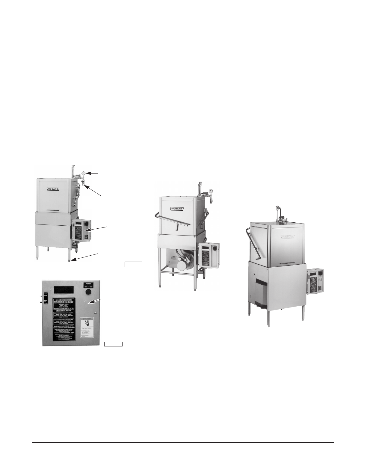
Model AM14
Pressure Gauge
Line Strainer Make Fill Connection Here
Control Box
Turn Feet to
Level Machine
PL-40827-1
NEW
CONTROL
BOX
PL-41176-1
Model AM14C
Model AM14
with Booster Heater
Fig. 1
DO NOT attempt to operate this dishwasher in the chemical sanitizing mode without a properly
installed, NSF-listed, chemical sanitizer feeder (not supplied with machine). Contact an authorized
detergent representative for information about a chemical sanitizer feeder.
The pump motor is rated 1 H.P. and has thermal overload protection.
The fill line incorporates an atmospheric vacuum breaker to prevent any reverse flow of water from the
dishwasher into the potable water supply.
A float, located in the wash tank, will shut off the heat supply if the water level becomes too low. When
the water returns to a proper level, the heating circuit is again operational.
– 4 –
Available as an optional accessory is a frame-mounted 10KW electric booster to maintain a minimum
final rinse temperature of 180°F.
Also available as an optional accessory is the model IB57 Infrared Booster Gas Water Heater.
Also available are circuit breaker(s) and/or single point electrical connection options.
INSTALLATION
UNPACKING
Immediately after unpacking the dishwasher, check for possible shipping damage. If this machine is
found to be damaged, save the packaging material and contact the carrier within 15 days of delivery.
Prior to installation, test the electrical service to make sure it agrees with the specifications on the
machine data plate (and booster data plate if applicable). The dishwasher data plate is located either
on the front of the upper wash tank, viewable after the front panel is removed, or on the side of the
control box. A separate data plate for the electric booster is located on the back side of the booster
(when equipped).
INSTALLATION CODES
Installation must be in accordance with state and local codes, or in the absence of local codes, with
the National Fuel Gas Code, ANSI Z223.1 (latest edition) if applicable, and the National Electrical Code
ANSI/NFPA 70 (latest edition). In Canada, the installation standards are: CAN/CGA B149.1,
CAN/CGA B149.2, and CSA C22.2 No.1 (latest editions).
LOCATION
Place the dishwasher in its operating location. Before finalizing the location, make sure that
consideration has been given for the electrical conduit, water supply, drain connection, steam or gas
supply and venting (if applicable), tabling (if needed), chemical feeder replenishment (if applicable),
and adequate clearance for opening the doors. Allow adequate clearance for service.
5
The control box (Fig. 1) is mounted 4
/8" below the dish
table when shipped from the factory. It can be changed
5
/8" or 31/8" below the dish table by removing the
to 12
two mounting bolts and reinstalling them in the holes
provided.
The dishwasher must be level before any connections
are made. Turn the threaded feet (Fig. 1) as required
to level the machine and adjust to the desired height.
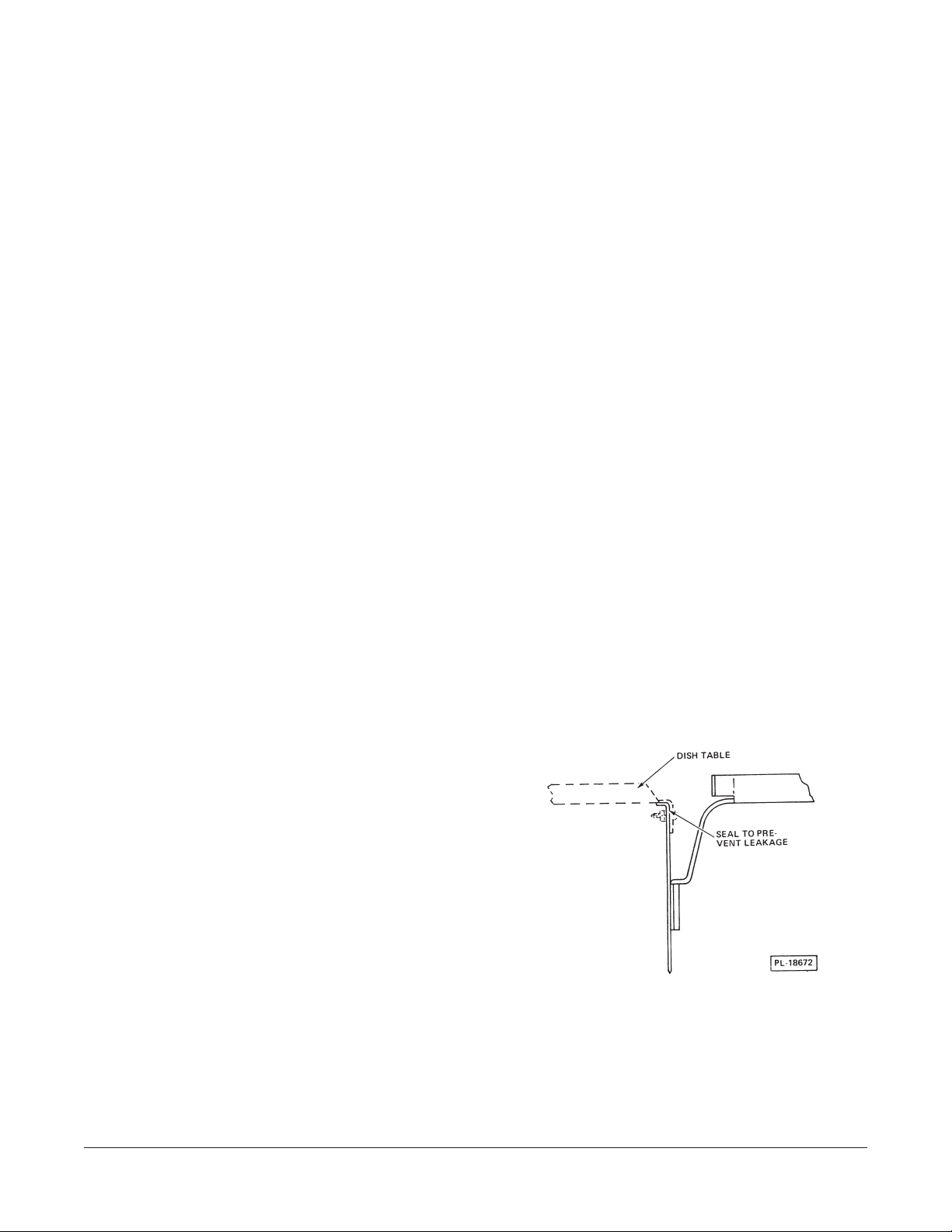
Dish tables should be turned down and fitted into the
dishwasher (Fig. 2). Use an NSF approved sealer
between table and tank lip to prevent leakage. Fasten
Fig. 2
the tables to the tank lip with truss head screws.
High-temperature or gas heat dishwashers will probably require a hood or vent over the dishwasher
in order to meet local codes. Low-temperature chemical sanitizing machines or low usage electric or
steam heat dishwashers may not require individual venting of the machine if the room is amply
exhausted. Refer to pages 8 and 9 for venting and hood requirements.
– 5 –

WATER REQUIREMENTS
Proper water quality can improve ware washing performance by reducing spotting, lowering chemical
supply costs, enhancing effectiveness of labor, and extending equipment life. Local water conditions
vary from one location to another. The recommended proper water treatment for effective and efficient
use of this equipment will also vary depending on the local water conditions. Ask your municipal water
supplier for details about local water specifics prior to installation.
Recommended water hardness is 4 – 6 grains of hardness per gallon. Chlorides must not exceed 50
parts per million. Water hardness above 6 grains per gallon should be treated by a water conditioner
(water softener or in-line treatment). Water hardness below 4 grains per gallon also requires a water
treatment to reduce potential corrosion. Water treatment has been shown to reduce costs associated
with machine cleaning, reduce deliming of the dishwasher, reduce detergent usage, and reduce
corrosion of metallic surfaces in the booster water heater and dishwasher.
Sediment, silica, chlorides, or other dissolved solids may lead to a recommendation for particulate
filtration or reverse osmosis treatment.
If an inspection of the dishwasher or booster heater reveals lime build-up after the equipment has been
in service, in-line water treatment should be considered, and, if recommended, should be installed and
used as directed. Contact your Hobart Service office for specific recommendations.
PLUMBING CONNECTIONS
WARNING:
AND PLUMBING CODES.
PLUMBING CONNECTIONS MUST COMPLY WITH APPLICABLE SANITARY, SAFETY,
DRAIN CONNECTION
The drain connection is made using 2" pipe.
If a right hand drain is desired, it can be changed from the standard left-hand by removing the pipe plug
from the drain valve and reinstalling it in the opposite end of the drain valve.
If a grease trap is required by code, it should have a minimum flow capacity of 42 gallons per minute.
WATER CONNECTION
A suitable water hammer arrestor should be installed in the water line just ahead of the dishwasher.
Without Electric or Gas Booster Water Heater
The water supply line is connected to the line strainer (Fig. 1) with
3
/4" pipe.
Minimum water temperatures are listed below:
Sanitizing Mode Wash Rinse
Hot Water 150°F (66°C) 180°F (82°C)
Chemical (Normal Duty) 120°F (49°C)* 120°F (49°C)*
Chemical (Light Duty) 130°F (54°C)* 120° F (49°C)*
* Temperatures shown are minimum; recommended temperature is 140°F (60°C).
Proper dishwasher operation requires a flowing pressure of 20 ± 5 psig at the dishwasher. If the
flowing pressure exceeds 25 psig, a pressure reducing valve (not supplied) must be installed in the
water supply line. CAUTION: The water pressure regulator must have a relief by-pass. Failure
to use the proper type of pressure regulator may result in damage to the unit.
A pressure gauge (Fig. 1) is provided for verification of proper water pressure. Present models
monitor the water pressure when the solenoid valve is open and water is flowing. On earlier models
where the pressure gauge was connected into a petcock, the petcock MUST always remain closed
except when making an instantaneous check of flowing pressure.
– 6 –
 Loading...