


 Loading...
SERVICE MANUAL
Color Inkjet Printer
EPSON Stylus C63/C64/C83/C84
 ®
®
Notice
All rights reserved. No part of this manual may be reproduced, stored in a retrieval system, or transmitted in any form or by any means electronic, mechanical, photocopying, or otherwise, without the prior written permission of SEIKO EPSON CORPORATION.
The contents of this manual are subject to change without notice.
All effort have been made to ensure the accuracy of the contents of this manual. However, should any errors be detected, SEIKO EPSON would greatly appreciate being informed of them.
The above not withstanding SEIKO EPSON CORPORATION can assume no responsibility for any errors in this manual or the consequences thereof.
EPSON is a registered trademark of SEIKO EPSON CORPORATION.
General Notice:Other product names used herein are for identification purpose only and may be trademarks or registered trademarks of their respective owners. EPSON disclaims any and all rights in those marks.
Copyright © 2000 SEIKO EPSON CORPORATION.
TPCS Quality Assurance Dept.
PRECAUTIONS
Precautionary notations throughout the text are categorized relative to 1)Personal injury and 2) damage to equipment.
DANGER Signals a precaution which, if ignored, could result in serious or fatal personal injury. Great caution should be exercised in performing procedures preceded by DANGER Headings.
WARNING Signals a precaution which, if ignored, could result in damage to equipment.
The precautionary measures itemized below should always be observed when performing repair/maintenance procedures.
DANGER
1.ALWAYS DISCONNECT THE PRODUCT FROM THE POWER SOURCE AND PERIPHERAL DEVICES PERFORMING ANY MAINTENANCE OR REPAIR PROCEDURES.
2.NO WORK SHOULD BE PERFORMED ON THE UNIT BY PERSONS UNFAMILIAR WITH BASIC SAFETY MEASURES AS DICTATED FOR ALL ELECTRONICS TECHNICIANS IN THEIR LINE OF WORK.
3.WHEN PERFORMING TESTING AS DICTATED WITHIN THIS MANUAL, DO NOT CONNECT THE UNIT TO A POWER SOURCE UNTIL INSTRUCTED TO DO SO. WHEN THE POWER SUPPLY CABLE MUST BE CONNECTED, USE EXTREME CAUTION IN WORKING ON POWER SUPPLY AND OTHER ELECTRONIC COMPONENTS.
4.WHEN DISASSEMBLING OR ASSEMBLING A PRODUCT, MAKE SURE TO WEAR GLOVES TO AVOID INJURIER FROM METAL PARTS WITH SHARP EDGES.
WARNING
1.REPAIRS ON EPSON PRODUCT SHOULD BE PERFORMED ONLY BY AN EPSON CERTIFIED REPAIR TECHNICIAN.
2.MAKE CERTAIN THAT THE SOURCE VOLTAGES IS THE SAME AS THE RATED VOLTAGE, LISTED ON THE SERIAL NUMBER/ RATING PLATE. IF THE EPSON PRODUCT HAS A PRIMARY AC RATING DIFFERENT FROM AVAILABLE POWER SOURCE, DO NOT CONNECT IT TO THE POWER SOURCE.
3.ALWAYS VERIFY THAT THE EPSON PRODUCT HAS BEEN DISCONNECTED FROM THE POWER SOURCE BEFORE REMOVING OR REPLACING PRINTED CIRCUIT BOARDS AND/OR INDIVIDUAL CHIPS.
4.IN ORDER TO PROTECT SENSITIVE MICROPROCESSORS AND CIRCUITRY, USE STATIC DISCHARGE EQUIPMENT, SUCH AS ANTI-STATIC WRIST STRAPS, WHEN ACCESSING INTERNAL COMPONENTS.
5.REPLACE MALFUNCTIONING COMPONENTS ONLY WITH THOSE COMPONENTS BY THE MANUFACTURE; INTRODUCTION OF SECOND-SOURCE ICs OR OTHER NONAPPROVED COMPONENTS MAY DAMAGE THE PRODUCT AND VOID ANY APPLICABLE EPSON WARRANTY.

About This Manual
This manual describes basic functions, theory of electrical and mechanical operations, maintenance and repair procedures of the printer. The instructions and procedures included herein are intended for the experienced repair technicians, and attention should be given to the precautions on the preceding page.
Manual Configuration |
Symbols Used in this Manual |
This manual consists of six chapters and Appendix.
CHAPTER 1.PRODUCT DESCRIPTIONS
Provides a general overview and specifications of the product.
CHAPTER 2.OPERATING PRINCIPLES
Describes the theory of electrical and mechanical operations of the product.
CHAPTER 3.TROUBLESHOOTING
Describes the step-by-step procedures for the troubleshooting.
CHAPTER 4.DISASSEMBLY / ASSEMBLY
Describes the step-by-step procedures for disassembling and assembling the product.
CHAPTER 5.ADJUSTMENT
Provides Epson-approved methods for adjustment.
CHAPTER 6.MAINTENANCE
Provides preventive maintenance procedures and the lists of Epson-approved lubricants and adhesives required for servicing the product.
CHAPTER 7.APPENDIX
Provides the following additional information for reference:
•Connector pin assignments
•Electric circuit boards components layout
•Electrical circuit boards schematics
•Exploded diagram & Parts List
Various symbols are used throughout this manual either to provide additional information on a specific topic or to warn of possible danger present during a procedure or an action. Be aware of all symbols when they are used, and always read NOTE, CAUTION, or WARNING messages.
ADJUSTMENT |
Indicates an operating or maintenance procedure, practice |
REQUIRED |
or condition that, if not strictly observed, could result in |
|
injury or loss of life. |
CAUTION |
Indicates an operating or maintenance procedure, practice, |
|
or condition that, if not strictly observed, could result in |
|
damage to, or destruction of, equipment. |
CHECK |
May indicate an operating or maintenance procedure, |
POINT |
practice or condition that is necessary to accomplish a task |
|
efficiently. It may also provide additional information that is |
|
related to a specific subject, or comment on the results |
|
achieved through a previous action. |
WARNING |
I.ndicates an operating or maintenance procedure, practice |
|
or condition that, if not strictly observed, could result in injury |
|
or loss of life. |
|
Indicates that a particular task must be carried out |
|
according to a certain standard after disassembly and |
|
before re-assembly, otherwise the quality of the |
|
components in question may be adversely affected. |

|
|
Revision Status |
|
|
|
Revision |
Issued Date |
Description |
|
|
|
A |
2003/7/31 |
First Release |
|
|
|

CONTENTS
Disassembly and Assembly |
|
Overview......................................................................................................... |
8 |
Precautions ............................................................................................... |
8 |
Tools.......................................................................................................... |
9 |
Work Completion Check.......................................................................... |
10 |
Caution regarding assembling/disassembling |
|
of the printer mechanism, and how to ensure |
|
of quality on re-assembled product ...................................................... |
11 |
Disassembly ................................................................................................. |
12 |
Housing (Right/Left/Frame), Stacker Assy. removal ............................... |
13 |
ASF unit removal..................................................................................... |
14 |
Circuit board removal .............................................................................. |
15 |
Holder shaft unit removal ........................................................................ |
17 |
PS board unit removal............................................................................. |
19 |
CR motor removal ................................................................................... |
20 |
Paper guide upper removal ..................................................................... |
21 |
Front frame removal ................................................................................ |
22 |
CR unit removal....................................................................................... |
23 |
Paper eject roller removal ....................................................................... |
27 |
Paper guide front removal ....................................................................... |
28 |
Printer mechanism/Housing (Lower) removal ......................................... |
29 |
Ink system removal ................................................................................. |
32 |
PF motor removal.................................................................................... |
33 |
Adjustment |
|
Overview....................................................................................................... |
35 |
Required Adjustment............................................................................... |
35 |
Head Angular Adjustment ....................................................................... |
37 |
Bi-D Adjustment ...................................................................................... |
37 |
PF Adjustment......................................................................................... |
38 |
PW Adjustment........................................................................................ |
38 |
First Dot Adjustment................................................................................ |
39 |
Top Margin Adjustment ........................................................................... |
39 |
CR Motor Drive Torque Dispersion Measurement .................................. |
39 |
A4 Normal Print and A4 SF Paper Print.................................................. |
39 |
Maintenance |
|
Overview ...................................................................................................... |
41 |
Cleaning .................................................................................................. |
41 |
Service Maintenance............................................................................... |
41 |
Lubrication............................................................................................... |
43 |
Appendix |
|
Electrical Circuits.......................................................................................... |
48 |
Parts List ...................................................................................................... |
48 |

C H A P T E R
DISASSEMBLY AND ASSEMBLY

EPSON Stylus C63/64/83/84 |
Revision A |
1.1 Overview
This section describes procedures for disassembling the main components of the Stylus C63/64/83/84. Unless otherwise specified, disassembly units or components can be reassembled by reversing the disassembly procedure. Things, if not strictly observed, that could result in injury or loss of life are described under the heading “Warning”. Precautions for any disassembly or assembly procedures are described under the heading “CAUTION”. Chips for disassembling procedures are described under the heading “CHECK POINT”.
If the assembling procedure is different from the reversed procedure of the disassembling, the procedure is described under the heading “REASSEMBLY”.
Any adjustments required after reassembling the units are described under the heading “ADJUSTMENT REQUIRED”. When you have to remove any units or parts that are not described in this chapter, refer to the exploded diagrams in the appendix.
Read precautions described in the next section before starting.
1.1.1 Precautions
See the precautions given under the handling “WARNING” and “CAUTION” in the following column when disassembling or assembling EPSON Stylus PC63/64/83/84..
WARNING Disconnect the power cable before disassembling or assembling the printer.
If you need to work on the printer with power applied, strictly follow the instructions in this manual.
Wear protective goggles to protect your eyes from ink. If ink gets in your eye, flush the eye with fresh water and see a doctor immediately.
Always wear gloves for disassembly and reassembly to avoid iujury from sharp metal edges.
To protect sensitive microprocessors and circuitry, use static discharge equipment, such as anti-static wrist straps, when accessing internal components.
Never touch the ink or wasted ink with bare hands. If ink comes into contact with your skin, wash it off with soap and water immediately. If irritation occurs, contact a physician.
WARNING Avant de commencer, assure vous que l’imprimante soit eteinte et que le cordon d’alimentation soit debranche.
Veillez a jeter les piles usagees selon le reglement local.
CAUTION Risque d’explosion si la pile est remplacée incorrectment. Ne remplacer que par une pile du même type ou d’un type équivalent
recommandé par le fabricant. Eliminer les piles déchargées selon les lois et les règles de sécurité en vigueur.
When transporting the printer after installing the ink cartridge,
CAUTION be sure to pack the printer for transportation without removing the ink cartridge.
Use only recommended tools for disassembling, assembling or adjusting the printer.
Observe the specified torque when tightening screws.
Apply lubricants and adhesives as specified. (See Chapter 3 for details.)
Make the specified adjustments when you disassemble the printer.
(See Chapter 5 for details.)
Make sure the tip of the waste ink tube is located at correct position when reassembling the waste ink tube. Otherwise it will cause ink leakage.
Disassembly and Assembly |
Overview |
8 |

EPSON Stylus C63/64/83/84 |
Revision A |
1.1.2 Tools
Use only specified tools to avoid damaging of the printer.
|
Table 1-1. |
Tools |
|
|
|
|
|
Name |
Supplier |
|
Parts No. |
|
|
|
|
Phillips Screw Driver (No.2) |
EPSON |
|
B743800200 |
|
|
|
|
Tweezer |
EPSON |
|
B741000100 |
|
|
|
|
Hexagon Box Driver |
EPSON |
|
B741700100 |
(Opposite side : 5.5 mm) |
|
||
|
|
|
|
|
|
|
|
Disassembly and Assembly |
Overview |
9 |

EPSON Stylus C63/64/83/84 |
Revision A |
1.1.3 Work Completion Check
If any service is made to the printer, use the checklist shown below to confirm all works are completed properly and the printer is ready to be returned to the user.
Table 1-2. Work Completion Check
Classifi- |
Item |
|
Check Point |
Status |
|
|
|||||
cation |
|
||||
|
|
|
|
||
|
|
|
|
|
|
|
Self-test |
Is the operation normal? |
Checked |
||
|
Not necessary |
||||
|
|
|
|
||
|
|
|
|
|
|
|
On-line Test |
Is the printing successful? |
Checked |
||
|
Not necessary |
||||
|
|
|
|
||
|
Printhead |
Is ink discharged normally from |
Checked |
||
|
all the nozzles? |
Not necessary |
|||
|
|
||||
|
|
|
|
|
|
|
|
Does it move smoothly? |
Checked |
||
|
|
Not necessary |
|||
|
|
|
|
||
|
|
Is there any abnormal noise |
Checked |
||
|
Carriage |
during its operation? |
Not necessary |
||
|
|
|
|
||
|
Is there any dirt or foreign |
Checked |
|||
|
Mechanism |
||||
Main Unit |
|
objects on the CR Guide Shaft? |
Not necessary |
||
|
|
Is the CR Motor at the correct |
Checked |
||
|
|
temperature? |
Not necessary |
||
|
|
(Not too heated?) |
|||
|
|
|
|||
|
|
|
|
||
|
|
• Is paper advanced smoothly? |
Checked |
||
|
|
• |
No paper jamming? |
Not necessary |
|
|
|
• |
No paper skew? |
||
|
|
|
|||
|
Paper Feeding |
• |
No multiple feeding? |
|
|
|
• |
No abnormal noise? |
|
||
|
Mechanism |
|
|
|
|
|
Is the PF Motor at correct |
Checked |
|||
|
|
||||
|
|
temperature? |
Not necessary |
||
|
|
|
|
||
|
|
Is the paper path free of any |
Checked |
||
|
|
obstructions? |
Not necessary |
||
Adjustment |
Specified |
Are all the adjustment done |
Checked |
||
Adjustment |
correctly? |
Not necessary |
|||
|
|||||
|
|
|
|
|
|
Table 1-2. Work Completion Check
Classifi- |
Item |
Check Point |
Status |
|
cation |
||||
|
|
|
||
|
|
|
|
|
|
|
Are all the lubrication made at |
Checked |
|
Lubrication |
Specified |
the specified points? |
Not necessary |
|
Lubrication |
Is the amount of lubrication |
Checked |
||
|
||||
|
|
correct? |
Not necessary |
|
Function |
ROM Version |
Version: |
Checked |
|
Not necessary |
||||
|
|
|
||
|
Ink Cartridge |
Are the ink cartridges installed |
Checked |
|
|
correctly? |
Not necessary |
||
|
|
|||
Packing |
|
|
|
|
Protective |
Have all relevant protective |
Checked |
||
|
materials been attached to the |
Not necessary |
||
|
Materials |
|||
|
printer? |
|||
|
|
|
||
|
|
|
|
|
Others |
Attachments, |
Have all the relevant items been |
Checked |
|
Accessories |
included in the package? |
Not necessary |
||
|
||||
|
|
|
|
Disassembly and Assembly |
Overview |
10 |
EPSON Stylus C63/64/83/84 |
Revision A |
1.2Caution regarding assembling/disassembling of the printer mechanism, and how to ensure of quality on re-assembled product
On current low end models, we basically forbided to remove Housing (Lower) from Printer mechanism in your repair. This is because there is a possibility of main frame deformation when a part (such as Ink system) is removed from Printer mechanism without Housing (Lower).
Therefore, if you want to replace Ink system/PF motor, we recommend to replace with new Printer mechanism with Housing (Lower).
On these models, you have to remove Housing (Lower) from printer mechanism when replacing [Porous Pad] with new one.
Therefore, we clarify caution regarding assembling/disassembling of the printer mechanism without Housing (Lower), and how to ensure of quality on repaired productsin this section.
[Caution regarding assembling/disassembling of the printer mechanism]
1)Main frame
(a)Control of assembled standard position. [Reason]
The assembed accuracy of each part composed of Printer mechanism is based on Housing (Lower).
[Service treatment]
Confirm that there is no gap between main frame and Housing (Lower). [Reference]
To ensure the assembled accuracy, you have to control the assembled standard position of main frame against X/Y/Z-axis direction. [X-axis direction]
-Make sure that main frame is correctly placed on the groove of Housing (Lower).
-Make sure that there is no gap between main frame and Housing (Lower). [Y-axis direction]
Make sure that cut-out portion of main frame is correctly placed on the square protrusion of Housing (Lower).
[Z-axis direction]
-Make sure that there is no gap between main frame and Housing (Lower).
-Make sure that the left side of Printer mechanism is correctly fixed by two hooks.
(b)Control of vertical level of guide rail (Guide rail means the portion latched by hooks of IC holder & Print head assy..)
[Reason]
There is a possibility that printing failre/operation failure occurs by guide rail deformation.
[Service treatment]
-Do not remove [Mounting Plate, M/B] from Printer mechanism.
-Hold up the specified position of main frame to avoid the deformation.
(c)How to assemble of ASF unit/Circuit board/Paper guide upper
[Reason]
There is a possibility that main frame deformation is caused extra force in assembling. As the result, printing failre/operation failure occurs.
[Service treatment]
Hold the opposite side by by hand while you are installing the above parts.
2)Front frame
(a)Control of vertical level [Reason]
There is a possibility that printing failre occurs by front frame deformation. [Service treatment]
Handle Front frame in assembling/disassembling carefully.
3)IC holder
(a)Handling of IC holder
[Reason]
If IC holder is damaged in assembling/disassembling of your repair, there is a possibility that vital problem occus in user’s futher operation.
[Service treatment]
Released two hooks of IC holder from the inside of IC holder by the tweezer.
[How to ensure of quality on re-assembled product]
We judge that the quality of re-assembled product is ensured if there is no problem about the print result by adjustment program..
Disassembly and Assembly Caution regarding assembling/disassembling of the printer mechanism, and how to ensure of quality on re-assembled product
EPSON Stylus C63/64/83/84 |
Revision A |
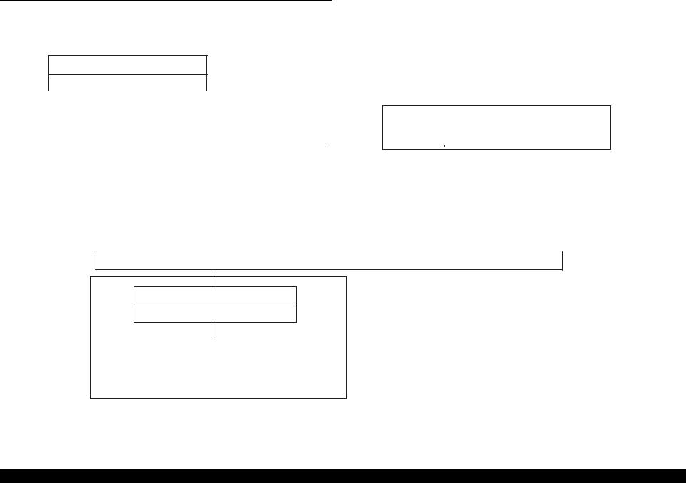
1.3 Disassembly
The flowchart below shows step-by-step disassembly procedures. When disassembling each unit, refer to the page number shown in the figure.
Housing (Right/Left/Frame), Stacker assy.
Page 13
|
|
|
|
|
|
|
|
|
|
|
|
|
|
|
|
|
|
|
|
|
|
|
|
*1) |
|
|
|
|
|
ASF unit removal |
|
CR motor removal |
|
Paper guide upper removal |
|
Front frame removal |
|
CR unit removal |
||||||
|
|
|
|
|
|
|
|
|
|
|
||||
Page 14 |
|
Page 20 |
|
Page 21 |
|
Page 22 |
|
Page 23 |
||||||
|
|
|
|
|
|
|
|
|
|
|
|
|
|
|
|
|
|
|
|
|
|
|
|
|
|
|
|
|
|
|
|
|
|
|
|
|
|
|
|
|
|
|
|
|
Circuit board removal |
|
Holder shaft unit removal |
|
|
|
|
|
|
|
Paper eject roller removal |
||||
|
|
|
|
|
|
|
|
|
|
|
|
|
||
Page 15 |
|
Page 17 |
|
|
|
|
|
|
|
Page 27 |
||||
|
|
|
|
|
|
|
|
|
|
|
|
|
|
|
|
|
|
|
|
|
|
|
|
|
|
|
|
|
|
PS board unit removal |
|
|
|
|
|
|
|
|
|
|
|
Paper guide front removal |
||
|
|
|
|
|
|
|
|
|
|
|
|
|
|
|
Page 19 |
|
|
|
|
|
|
|
|
|
|
|
Page 28 |
||
|
|
|
|
|
|
|
|
|
|
|
|
|
|
|
*2)
Printer mechanism/Housing (Lower) removal
Page 29
|
|
|
|
|
Ink system removal |
|
PF motor removal |
||
|
|
|
|
|
Page 32 |
|
Page 33 |
||
|
|
|
|
|
*1) In "Front frame removal", the procedure only for removing Front frame is mentioned.
In "CR unit removal, the sequencial procedure of all parts composed of CR unit is mentioned.
(Added operations before Front frame removal + Front frame removal + IC holder +Print head assy. / PW sensor
/ CR encoder sensor)
*2) There is some cautions regarding repair of these parts. As for the details, please refer to 1.2 "Caution regarding assembling/disassembling of the printer mechanism, and how to ensure of quality on re-assembled product!.
Figure 1-1. Disassembling flowchart
Disassembly and Assembly |
Disassembly |
12 |

EPSON Stylus C63/64/83/84 |
Revision A |
1.3.1 Housing (Right/Left/Frame), Stacker Assy. removal
External view
|
|
|
|
|
|
|
|
|
2 |
|
|
|
|
|
|
|
|
|
|
|
|
|
|
|
|
|
|
|
||
|
|
|
1 |
|
|
|
|
|
|
|
|
|
|
|
|
|
1 |
|
|
|
|
2 |
|
|
|
|
||||
|
|
|
|
|
|
|
|
|
|
|
|
|
|
|
|
|
|
|
|
|
|
|
|
|
||||||
|
|
|
|
|
|
|
|
|
|
|
|
|
|
|
|
|
|
|
|
|
|
|
|
|
|
|
|
|
|
|
|
|
|
|
|
|
|
|
|
|
|
|
|
|
|
|
|
|
|
|
|
|
|
|
|
|
|
|
|
|
|
|
|
|
|
|
|
|
|
|
|
|
|
|
|
|
|
|
|
|
|
|
|
|||||||||
|
|
3 |
|
|
|
|
|
|
|
|
|
|
|
4 |
|
|
|
|
3 |
|
|
|
|
|
|
|
|
4 |
|
|
|
|
|
|
|
|
|
|
|
|
|
|
|
|
|
|
|
|
|
|
|
|
|
|
|
|
|
|
|
|
|
|
|
|
|
|
|
|
|
|
|
|
|
|
|
|
|
|
|
|
|
|
|
|
|
|
|
|
|
|
|
|
|
|
|
|
|
|
|
|
|
|
|
|
|
|
|
|
|
|
|
|
|
|
|
|
|
|
|
|
|
|
|
|
|
|
|
|
|
5 |
|
|
|
|
|
|
|
|
|
|
|
|
|
|
|
|
5 |
|
|
|
|
|
|
|
Housing (Left) |
|
|
|
|
|
|
|
|
|
|
|
|
|
|
|
|
|
|
|
|
Housing (Right) |
|||||||||
|
|
|
|
|
|
|
|
|
|
|
|
|
|
|
|
|
|
|
|
|
|
|
|
|
|
|
|
|
|
|
|
|
|
|
|
|
|
|
|
|
|
|
|
|
|
|
|
|
|
|
|
|
|
|
|
|
|
|
|
|
|
|
|
|
|
|
|
|
|
|
|
|
|
|
|
|
|
|
|
|
|
|
|
|
|
|
|
|
|
|
|
|
|
|
|
|
|
|
|
|
|
|
|
|
|
|
|
|
|
|
|
|
|
|
|
|
|
|
|
|
|
|
|
Insert metal scale from this slit, and release one hook of I/F cover.
This hook is not only the right side but also the left side.
Damper
Front side |
|
Housing (Frame) |
|
Backside |
|
|
|
|
|
1
Stacker assy.
This marking is the hook that should be removed/installed.
This marking is more careful hooks in assembling/disassembling
This marking is the hook portion for Housing cover (Right/Left) and the order of assembling.
Figure 1-2. Housing (Right/Left/Frame) and Stacker assy. removal
Part/Unit that should be removed before removing Housing (Right/Left/ Frame) or Stacker assy..
Non
Removal procedure
[Housing (Right/Left/Frame) removal]
1)Releasing five hooks by hand/precision screwdriver (-), and remove Housing (Right).
2)Release one hook of I/F cover by inserting metal scale vertically from the slit on bottom of Housing (Left), and remove I/F cover.
3)Releasing five hooks by hand/precision screwdriver (-), and remove Housing (Left)
4)Release five hooks by hand/precision screwdriver (-), and remove Housing (Frame).
[Stacker assy. removal]
1)Push cut-out portion of Stacker Assy. (left side) by precision screwdriver (-), and pull Stacker assy. to the front side of the printer.
Do not damage hooks by hand/precision screwdriver (-) in
CAUTION |
removing Housing (Right/Left) & Stacker assy.. |
|
Do not tilt the printer too much when Housing (Right/Left/
Frame) is removed by hand/precision screwdriver (-). This is because ink may possible flow if the cap is not covered by the Print head. (CR is out of the home position)
When assembling Housing (Right/Left/Frame) or Stacker assy. to printer mechanism,
Hook five ribs for securing Housing cover (Right/Left) to Housing (Right/Left) in the order indicated in the figure.
Make sure that hooks/protrusions of Housing (Right/ Left/Frame), Stacker assy., SW bottom and Panel board is correctly fixed to Housing (Frame/Lower).
Make sure that there is not the clearance between Housing (Right/Left/Frame) and Housing (Lower).
Make sure that damper for Stacker assy. is correctly installed to the Housing (Lower).
Disassembly and Assembly |
Disassembly |
13 |
EPSON Stylus C63/64/83/84 |
Revision A |
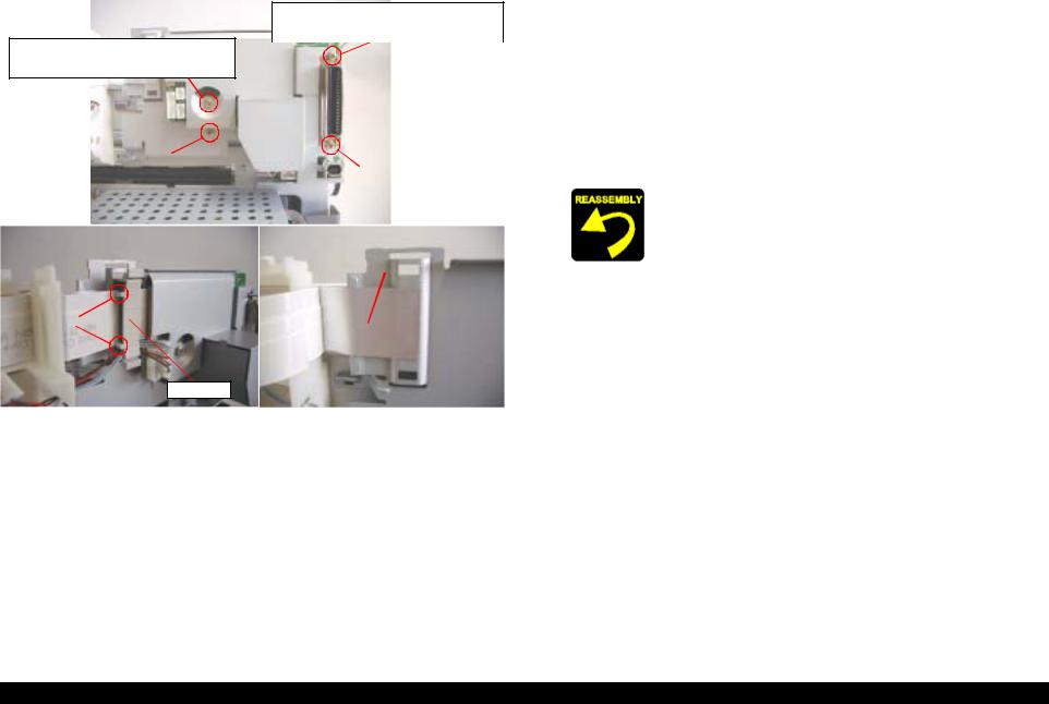
1.3.2 ASF unit removal
External view
Screw type : C.B.P-TITE, 3x8, F/SN |
|
|
|
|
|
|
|
|
|
|
|
|
|
|
|||||||
|
|
Order of tightening : Third |
|
|
|
|
|
|
|
|
|
|
|
|
|
|
|||||
Thghtening torque : 6±1 kgf.cm |
|
|
|
|
|
|
Screw type : C.B.S-TITE (P4), 3x6, F/SN |
|
|||||||||||||
|
|
|
|
|
|
|
|
|
|
|
|
|
|
|
Order of tightening : Second |
|
|||||
|
|
|
|
|
|
|
|
|
|
|
|
|
|
|
|||||||
|
|
|
|
|
|
|
|
|
|
|
|
|
|
|
Thghtening torque : 8±1 kgf.cm |
|
|||||
|
|
|
|
|
|
|
|
|
|
|
|
|
|
|
|
|
|
|
|
|
|
|
|
|
|
|
|
|
|
|
|
|
|
|
|
|
|
|
|
|
|
|
|
|
|
|
|
|
|
|
|
|
|
|
|
|
|
|
|
|
|
|
|
|
|
|
|
Screw type : C.B.S SCREW, 3x6, F/SN |
|
|
|
|
|
|
|
|
|
|
|
||||||||
|
|
|
Order of tightening : First |
|
|
|
|
|
|
|
|
|
|
|
|
|
|||||
|
|
|
Thghtening torque : 8±1 kgf.cm |
|
|
|
|
|
|
|
|
|
|
|
|||||||
|
|
|
|
|
|
|
|
|
|
|
|
|
|
|
|
|
|
|
|
|
|
|
|
|
|
|
|
|
|
|
|
|
|
|
|
|
|
|
|
|
|
|
|
|
|
|
|
|
|
|
|
|
|
ASF unit (Backside) |
|
|
|
|
|
|
|
||||
|
|
|
|
|
|
|
|
|
|
|
|
|
|
|
|
||||||
|
|
|
|
|
|
|
|
|
|
|
|
Ribs of ASF frame |
|
|
|
|
|
||||
|
|
|
|
|
|
|
|
|
|
|
|
|
|
|
|
|
|
|
|
|
|
|
2 |
|
|
|
|
|
|
|
|
|
|
|
|
|
|
|
|
|
|
||
|
|
|
|
|
|
|
|
|
|
|
|
1 |
|
|
|
|
|
|
|
This marking is |
|
|
|
|
|
|
|
|
|
|
|
|
|
|
|
|
|
|
|
|
|||
|
|
|
|
|
|
|
|
|
|
|
|
|
|
|
|
|
1 |
dowel/latched |
|||
|
|
|
|
|
|
|
|
|
|
|
|||||||||||
|
|
|
1 |
|
|
|
|
|
|
|
|
|
|
|
|
|
|
|
|||
|
|
|
|
|
|
|
|
|
|
|
|
|
|
|
|
|
|
|
|
position and the |
|
|
|
|
|
|
|
|
|
|
|
|
|
|
|
|
|
|
|
|
|
||
|
|
|
|
|
|
|
|
|
|
|
|
|
|
|
|
|
|
|
|
order of assembling. |
|
|
|
|
|
|
|
|
|
|
|
|
|
|
|
|
|
|
|
|
|
||
|
|
|
|
|
|
|
|
|
|
|
|
2 |
|
|
|
|
|
|
|
|
|
|
|
|
|
|
|
|
|
|
|
|
|
|
|
|
|
|
|
|
|
|
|
|
|
Compression spring 1.88 |
|
|
Extension spring 0.585 |
|
|
|
|
|
|
||||||||||
|
|
|
|
|
|
|
|
|
|
|
|
|
|
|
|
|
|
||||
|
|
|
1 |
|
|
|
|
|
|
|
|
|
2 |
|
|
|
|
|
|
|
|
|
|
|
|
|
|
|
|
|
|
|
|
|
|
|
|
|
|
|
|
|
|
Paper return lever
Figure 1-3. ASF unit removal
Part/Unit that should be removed before removing ASF unit
Housing (Right/Left/Frame)
Removal procedure
1)Remove three screws for securing ASF unit to main frame, and remove the unit with pulling up slightly to the backside of the printer.
2)Release left protrusion of Hopper by pulling its bottom toward the front side, and remove Hopper from ASF frame.
3)Release Extension spring 0.585 for Paper return lever, and remove the lever with releasing two protrusions.
4)Release Compression spring 1.88 for Returd roller unit, and turn the roller unit until it is free.
When assembling ASF unit,
Make sure to latch Extension spring 0.585 for Paper return lever & Compression spring 1.88 for Returd roller unit in the order indicated in the figure, and to set Expression spring 0.585 between ribs of ASF frame.
Make sure that Paper return lever & Returd roller unit move smoothly.
Do not touch returd roller and cork on Hopper.
Hook two dowels for securing Paper return lever to ASF frame in the order incicated in the figure.
When assembling ASF unit to main frame,
Make sure to install Compression spring 2.53 for Hopper correctly.
Make sure that Hopper moves smoothly.
Make sure to set ASF unit with the flat surface of LD roller up.
ADJUSTMENT
REQUIRED
Fasten three screws for securing ASF unit in the order/ tightening torque indicated in the figure.
Make sure that there is no gap between ASF unit and Shield plate (upper) of PS board unit.
When you replace ASF unit with new one, lubricate it with the suitable amount of G-26 grease by the specified position.
When ASF unit is removed or replaced with new one, the following adjustment must be performed in the order below.
1)Top margin adjustment
2)1st dot adjustment
Disassembly and Assembly |
Disassembly |
14 |
EPSON Stylus C63/64/83/84 |
Revision A |
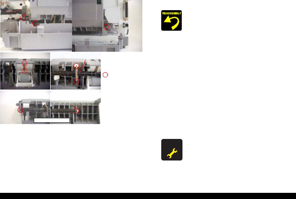
1.3.3 Circuit board removal
External view
Screw type : C.B.S TITE SCREW, 3x14, F/SN
Order of tightening : First
Thghtening torque : 8±1 kgf.cm Screw type : C.B.S TITE SCREW, 3x10, F/SN 
Order of tightening : Third Thghtening torque : 8±1 kgf.cm
Screw type : C.B.S TITE SCREW, 3x6, F/SN |
|
|
|
|
|
|
|||||
|
Order of tightening : 4th |
|
|
|
|
Screw type : C.B.S TITE SCREW, 3x14, F/SN |
|||||
|
|
|
|
|
|
Order of tightening : Second |
|||||
Thghtening torque : 8±1 kgf.cm |
|
|
|
|
|
||||||
|
|
|
|
Thghtening torque : 8±1 kgf.cm |
|||||||
|
|
|
|
|
|
|
|
||||
|
|
|
|
|
|
|
|
|
|
||
|
|
|
|
Main board (Backside) |
|
|
|
||||
|
|
|
|
|
|
|
|
|
|
|
|
|
|
|
|
|
Far side |
|
|
|
|
|
|
|
|
|
|
|
|
|
|
Shield Plate FFC |
|
||
|
|
|
|
|
|
|
|
|
|
|
|
HP side |
|
|
|
|
|
|
|
|
|
|
|
|
|
|
|
|
|
|
|
|
|
||
Dowel of cramp core |
|
|
|
|
|
|
|
|
|
|
|
Cramp core
Figure 1-4. Circuit board
Part/Unit that should be removed before removing Circuit board
Housing (Right/Left/Frame) / ASF unit
Removal procedure
1)Remove Clamp core from [Mounting Plate, M/B], and disconnect the following seven cables from the corresponding connectors on main board.
- CR motor connector cable |
: CN5 |
- PF motor connector cable |
: CN6 |
- Head FFC |
: CN7, CN8 |
- PE sensor cable |
: CN9 |
- Power supply connect cable |
: CN2 |
- Panel board connector cable |
: CN4 |
2)Remove four screws for securing Circuit board to main frame, and remove the board.
3)Remove [Shield Plate, M/B] from main board.
When assembling Circuit board,
Make sure that the metal fittings for locking the Parallel interface is on its shield plate.
When assembling Circuit board to main frame,
Make sure to connect all cables to the connectors (CN2, CN4, CN5, CN6, CN7, CN8, CN9) on main board in the correct direction.
Fasten four screws for securing Circuit board in the order/tightening torque indicated in the figure.
Make sure that Shield plate FFC on Head FFC is securely pasted on [Mounting Plate, M/B].
Make sure that two dowels of Clamp core is set in home position direction.
Make sure that PE sensor cable & CR motor connector cable are set on Holder shaft unit, and in Clamp core.
Disassembly and Assembly |
Disassembly |
15 |
Loading...