


 Loading...
SERVICE MANUAL
Scanner • Printer • Copier
EPSON Stylus CX3100/3200
|
|
|
|
|
|
|
|
|
|
|
|
|
|
|
|
|
|
|
|
® |
SEOT02002 |
|
|
|
|
|
|
|
|
|
|
|
|
|
|
|
|
|
|
|
|
|
|
|
|
|
|
|
|
|
|
|
|
|
|
|
|
|
|
|
|
|
|
|
|
|
|
|
|
|
|
|
|
|
|
|
|
|
|
|
|
|
|
|
|
|
|
|
|
|
|
|
|
|
|
|
|
|
|
|
|
|
|
|
|
|
|
|
|
Notice
All rights reserved. No part of this manual may be reproduced, stored in a retrieval system, or transmitted in any form or by any means electronic, mechanical, photocopying, or otherwise, without the prior written permission of SEIKO EPSON CORPORATION.
All effort have been made to ensure the accuracy of the contents of this manual. However, should any errors be detected, SEIKO EPSON would greatly appreciate being informed of them.
The contents of this manual are subject to change without notice.
The above not withstanding SEIKO EPSON CORPORATION can assume no responsibility for any errors in this manual or the consequences thereof.
EPSON is a registered trademark of SEIKO EPSON CORPORATION.
General Notice: |
Other product names used herein are for identification purpose only and may be trademarks or registered trademarks of their |
|
respective owners. EPSON disclaims any and all rights in those marks. |
Copyright © 2002 SEIKO EPSON CORPORATION.
Imaging & Information Product Division
TPCS Quality Assurance Department
|
PRECAUTIONS |
Precautionary notations throughout the text are categorized relative to 1)Personal injury and 2) damage to equipment. |
|
DANGER |
Signals a precaution which, if ignored, could result in serious or fatal personal injury. Great caution should be exercised in performing |
|
procedures preceded by DANGER Headings. |
WARNING |
Signals a precaution which, if ignored, could result in damage to equipment. |
The precautionary measures itemized below should always be observed when performing repair/maintenance procedures.
DANGER
1.ALWAYS DISCONNECT THE PRODUCT FROM THE POWER SOURCE AND PERIPHERAL DEVICES PERFORMING ANY MAINTENANCE OR REPAIR PROCEDURES.
2.NO WORK SHOULD BE PERFORMED ON THE UNIT BY PERSONS UNFAMILIAR WITH BASIC SAFETY MEASURES AS DICTATED FOR ALL ELECTRONICS TECHNICIANS IN THEIR LINE OF WORK.
3.WHEN PERFORMING TESTING AS DICTATED WITHIN THIS MANUAL, DO NOT CONNECT THE UNIT TO A POWER SOURCE UNTIL INSTRUCTED TO DO SO. WHEN THE POWER SUPPLY CABLE MUST BE CONNECTED, USE EXTREME CAUTION IN WORKING ON POWER SUPPLY AND OTHER ELECTRONIC COMPONENTS.
4.WHEN DISASSEMBLING OR ASSEMBLING A PRODUCT, MAKE SURE TO WEAR GLOVES TO AVOID INJURIER FROM METAL PARTS WITH SHARP EDGES.
WARNING
1.REPAIRS ON EPSON PRODUCT SHOULD BE PERFORMED ONLY BY AN EPSON CERTIFIED REPAIR TECHNICIAN.
2.MAKE CERTAIN THAT THE SOURCE VOLTAGES IS THE SAME AS THE RATED VOLTAGE, LISTED ON THE SERIAL NUMBER/RATING PLATE. IF THE EPSON PRODUCT HAS A PRIMARY AC RATING DIFFERENT FROM AVAILABLE POWER SOURCE, DO NOT CONNECT IT TO THE POWER SOURCE.
3.ALWAYS VERIFY THAT THE EPSON PRODUCT HAS BEEN DISCONNECTED FROM THE POWER SOURCE BEFORE REMOVING OR REPLACING PRINTED CIRCUIT BOARDS AND/OR INDIVIDUAL CHIPS.
4.IN ORDER TO PROTECT SENSITIVE MICROPROCESSORS AND CIRCUITRY, USE STATIC DISCHARGE EQUIPMENT, SUCH AS ANTI-STATIC WRIST STRAPS, WHEN ACCESSING INTERNAL COMPONENTS.
5.DO NOT REPLACE IMPERFECTLY FUNCTIONING COMPONENTS WITH COMPONENTS WHICH ARE NOT MANUFACTURED BY EPSON. IF SECOND SOURCE IC OR OTHER COMPONENTS WHICH HAVE NOT BEEN APPROVED ARE USED, THEY COULD CAUSE DAMAGE TO THE EPSON PRODUCT, OR COULD VOID THE WARRANTY OFFERED BY EPSON.

About This Manual
This manual describes basic functions, theory of electrical and mechanical operations, maintenance and repair procedures of the printer. The instructions and procedures included herein are intended for the experienced repair technicians, and attention should be given to the precautions on the preceding page.
Manual Configuration |
Symbols Used in this Manual |
This manual consists of six chapters and Appendix.
CHAPTER 1. PRODUCT DESCRIPTIONS
Provides a general overview and specifications of the product.
CHAPTER 2. OPERATING PRINCIPLES
Describes the theory of electrical and mechanical operations of the product.
CHAPTER 3. TROUBLESHOOTING
Describes the step-by-step procedures for the troubleshooting.
CHAPTER 4. DISASSEMBLY / ASSEMBLY
Describes the step-by-step procedures for disassembling and assembling the product.
CHAPTER 5. ADJUSTMENT
Provides Epson-approved methods for adjustment.
CHAPTER 6. MAINTENANCE
Provides preventive maintenance procedures and the lists of Epson-approved lubricants and adhesives required for servicing the product.
APPENDIX Provides the following additional information for reference:
•Connector pin assignments
•Electric circuit boards components layout
•Electrical circuit boards schematics
•Exploded diagram & Parts List
Various symbols are used throughout this manual either to provide additional information on a specific topic or to warn of possible danger present during a procedure or an action. Be aware of all symbols when they are used, and always read NOTE, CAUTION, or WARNING messages.
Indicates an operating or maintenance procedure, practice
ADJUSTMENT |
or condition that is necessary to keep the product’s quality. |
REQUIRED |
CAUTION
Indicates an operating or maintenance procedure, practice, or condition that, if not strictly observed, could result in damage to, or destruction of, equipment.
CHECK
May indicate an operating or maintenance procedure,
POINT practice or condition that is necessary to accomplish a task efficiently. It may also provide additional information that is related to a specific subject, or comment on the results achieved through a previous action.
I.ndicates an operating or maintenance procedure, practice WARNING or condition that, if not strictly observed, could result in injury
or loss of life.

|
|
Revision Status |
|
|
|
|
|
Revision |
Issued Date |
|
Description |
|
|
|
|
A |
Augusut 1,2002 |
|
First Release |
|
|
|
|
|
|
|
|
|
|
|
|
|
|
|
|
|
|
|
|

EPSON Stylus CX3100/3200 |
Revision A |
Contents
Chapter 1 PRODUCT DESCRIPTION |
|
1.1 Overview ............................................................................................................... |
9 |
1.1.1 Basic Functions............................................................................................. |
9 |
1.1.2 Common ....................................................................................................... |
9 |
1.1.2.1 Electrical Specifications ........................................................................ |
9 |
1.1.2.2 Interface............................................................................................... |
10 |
1.1.2.3 Conformity to Safety and EMC Standards.......................................... |
10 |
1.1.2.4 Environmental Conditions................................................................... |
10 |
1.1.2.5 Reliability ............................................................................................ |
11 |
1.1.2.6 Acoustic Noise .................................................................................... |
11 |
1.1.2.7 Weight and Overall Dimensions ......................................................... |
11 |
1.2 Media Specifications ........................................................................................... |
12 |
1.2.1 Black Ink Cartridge..................................................................................... |
12 |
1.2.2 Color Ink Cartridge..................................................................................... |
12 |
Chapter 2 Operating Principles |
|
2.1 Overview ............................................................................................................. |
14 |
2.1.1 Mechanism.................................................................................................. |
14 |
2.1.1.1 Printer Mechanism .............................................................................. |
14 |
2.1.1.2 Scanner Mechanism ............................................................................ |
15 |
2.1.2 Electric Circuit............................................................................................ |
15 |
Chapter 3 Troubleshooting |
|
3.1 Troubleshooting at Unit Level............................................................................. |
18 |
3.1.1 Printer / Scanner does not operate at all |
|
even with power turned on ........................................................................ |
20 |
3.1.2 Error is detected.......................................................................................... |
21 |
3.1.3 Trouble related to Print............................................................................... |
21 |
3.1.4 Paper feeding is not normally carried out................................................... |
22 |
3.1.5 Operation Panel faulty ................................................................................ |
22 |
3.2 Troubleshooting for Printer ................................................................................. |
23 |
3.3 Troubleshooting for Scanner ............................................................................... |
30 |
3.4 Troubleshooting for Motors and Sensors ............................................................ |
33 |
Chapter 4 Disassembly and Assembly |
|
4.1 Overview ............................................................................................................. |
35 |
4.1.1 Precautions.................................................................................................. |
35 |
4.1.2 Tools ........................................................................................................... |
36 |
4.1.3 Screws......................................................................................................... |
36 |
4.1.4 Service Dispatch Standard.......................................................................... |
37 |
4.2 Disassembly Process ........................................................................................... |
38 |
4.2.1 Scanner Unit Removal................................................................................ |
38 |
4.3 Scanner Unit Disassembly................................................................................... |
40 |
4.3.1 Hinge Removal ........................................................................................... |
40 |
4.3.2 Upper Housing Removal ............................................................................ |
41 |
4.3.3 Motor Unit Removal................................................................................... |
42 |
4.3.4 CCD Module Removal ............................................................................... |
43 |
4.3.5 Panel Circuit Board Removal ..................................................................... |
43 |
4.4 Disassembly of Printer ........................................................................................ |
44 |
4.4.1 Middle Housing Removal........................................................................... |
44 |
4.4.2 Print Head Removal.................................................................................... |
46 |
4.4.3 ASF Unit Removal ..................................................................................... |
48 |
4.4.4 Waste Ink Pad Removal ............................................................................. |
49 |
4.4.5 CR Motor Removal .................................................................................... |
50 |
4.4.6 Holder Shaft Unit Removal ........................................................................ |
52 |
4.4.7 Front Frame Unit Removal......................................................................... |
53 |
4.4.8 Main Board Removal.................................................................................. |
54 |
4.4.9 Power Unit Removal .................................................................................. |
56 |
Chapter 5 Adjustment |
|
5.1 Overview ............................................................................................................. |
58 |
5.1.1 Printer Mechanism Adjustment Items ........................................................ |
58 |
5.1.2 Dedicated Tools.......................................................................................... |
59 |
5.2 Adjustment by Adjustment Program................................................................... |
59 |
6

EPSON Stylus CX3100/3200 |
Revision A |
|
|
5.2.1 Adjustment Program Installation................................................................ |
59 |
|
5.2.2 Adjustment Program Start .......................................................................... |
60 |
|
5.2.3 Destination Setting (EEPROM Initialization) ............................................ |
61 |
|
5.2.4 Head ID Input ............................................................................................. |
62 |
|
5.2.5 Bi-D Adjustment......................................................................................... |
63 |
|
5.2.6 USB ID Input.............................................................................................. |
65 |
|
5.2.7 Top Margin Adjustment ............................................................................. |
66 |
|
5.2.8 First Dot Position Adjustment .................................................................... |
67 |
|
5.2.9 Head Cleaning ............................................................................................ |
68 |
|
5.2.10 Ink Charge ................................................................................................ |
68 |
|
5.2.11 Protection Counter .................................................................................... |
69 |
|
5.2.12 EEPROM Data Backup ............................................................................ |
70 |
|
5.2.13 Check Pattern Printing.............................................................................. |
70 |
|
5.2.13.1 A4 Plain Paper Printing..................................................................... |
70 |
|
5.2.14 EEPROM Data.......................................................................................... |
71 |
5.3 |
Firmware Uploading............................................................................................ |
72 |
Chapter 6 Maintenance |
|
|
6.1 |
Overview ............................................................................................................. |
75 |
|
6.1.1 Cleaning...................................................................................................... |
75 |
|
6.1.2 Maintenance of the Scanner........................................................................ |
75 |
|
6.1.2.1 Lubrication Points of the Scanner (TBD)............................................ |
75 |
|
6.1.3 Maintenance of the Printer.......................................................................... |
76 |
|
6.1.3.1 Head Cleaning ..................................................................................... |
76 |
|
6.1.3.2 Maintenance Error............................................................................... |
76 |
|
6.1.3.3 Lubrication Points of the Printer ......................................................... |
76 |
Chapter 7 Appendix |
|
|
7.1 |
Connectors........................................................................................................... |
81 |
|
7.1.1 Connector Assignments .............................................................................. |
81 |
7.2 |
Circuit Board Component Layout ....................................................................... |
82 |
7.3 |
Electric Circuit Diagrams .................................................................................... |
83 |
7.4 |
Exploded Diagrams ............................................................................................. |
88 |
7.5 |
ASP List............................................................................................................... |
89 |
7

C H A P T E R
1
PRODUCT DESCRIPTION

EPSON Stylus CX3100/3200 |
Revision A |
1.1 Overview
This section describes the specifications for the SPC (Scanner, Printer, Copier) machine “Stylus CX3100/3200”.
1.1.1 Basic Functions
The functions of Stylus CX3100/3200 are as described below:
Printer function
The Printer function produces photo quality output on the Epson special coated papers with BorderFree feature.
Print head
Bk: 48 nozzles in each of 3 rows (144 nozzles in total) YMC: 48 nozzles for each
Scanner function
The image can easily be acquired on the PC by means of the “Scan” button.
The maximum optical resolution of scanning is 600 dpi x 1200 dpi and pixel depth is 48-bit at the ADC output, 24-bit when passing to a PC.
Standalone Copier function
The Product has the Standalone Copier function that reproduces photo quality copies on the Epson special coated papers without PCs. The use of the latest print technology mounted on the Product achieves the highest standalone copy speed among the same class of the products.
Standard Copy mode
This mode is used for the standard copier function. The bottom margin is 14 mm.
BorderFree Copy mode Photograph copy
Small Margin Copy mode
The minimum copy margin is 1.5 mm.
Reduced (Minimize) Margin Copy mode
This mode is basically the same as the standard copy mode, but the bottom margin is 3 mm.
Repeat Copy mode
Mini photo stickers can be produced.
2-up Copy mode
Two pages of the original is shrunk and printed on one page. Consumption of copy paper can be saved.
Mirror Copy mode
The original can be flipped from left to right and copied onto the Iron-on Cool Peel Transfer Paper.
1.1.2 Common
The specifications described below are common to the scanner and printer.
1.1.2.1 Electrical Specifications
Table 1-1. AC Input
|
100 V Model |
|
120 V Model |
220-240 V Model |
|
|
|
|
|
Rated voltage (VAC) |
100 |
|
120 |
220-240 |
|
|
|
|
|
Input voltage (VAC) |
90-110 |
|
108-132 |
198-264 |
|
|
|
|
|
Rated current (A) |
0.6 |
|
0.6 |
0.3 |
|
|
|
|
|
Rated frequency range (Hz) |
|
50-60 |
|
|
|
|
|
|
|
Input frequency range (Hz) |
|
49.5-60.5 |
|
|
|
|
|
|
|
|
Approx. 22 W (Standalone copying, ISO10561 Letter |
|||
Power consumption (W) |
Patter, Plain Paper - Normal) |
|||
|
|
|
|
|
|
|
Approx. 6.5 W (Standby) |
||
|
|
|
|
|
PRODUCT DESCRIPTION |
Overview |
9 |

EPSON Stylus CX3100/3200 |
Revision A |
NOTE: The product is Energy Star compliant.
NOTE: The holding current to the motors is reduced when the printer has stayed in non-operation status for 5 minutes.
NOTE: The Scanner lamp is turned off when the Scanner has stayed in nonoperation status for 15 minutes.
1.1.2.2 Interface
In compliance with USB (Universal Serial Bus) Revision 1.1
Connector USB Series B
1.1.2.3 Conformity to Safety and EMC Standards
Table 1-2. Conformity to Safety and EMC Standards
|
|
100 V Model |
|
120 V Model |
|
220-240 V Model |
|
|
|
|
|
|
|
Safety |
|
- |
• |
UL1950 |
• |
EN 60950 |
|
• |
CSA22.2 No.950 |
|
|
||
|
|
|
|
|
||
|
|
|
|
|
|
|
|
• |
VCCI Class B |
• |
FCC part15 |
• |
EN 55022 (CISPR |
|
• Guideline for the Suppression |
|
subpart B class B |
|
Pub.22) class B |
|
|
|
of Harmonics in Household |
• |
CSA C108.8 class |
• |
EN 55024 |
EMC |
|
and General-Use Equipment |
|
B |
• |
EN 61000-3-2 |
|
|
|
|
|
• |
EN 61000-3-3 |
|
|
|
|
|
• |
AS/NZS 3548 |
|
|
|
|
|
|
Class B |
|
|
|
|
|
|
|
1.1.2.4 Environmental Conditions
Temperature
Operating 10 ~ 35 °C
Non-operating
-20 ~ 60 °C (In the shipment container.)
NOTE: 1 month at 40 °C or 120 hours at 60 °C
Humidity (no condensation)
Operating
20~ 80%RH
Non-operating
5~ 85%RH (In the shipment container.)
Resistance to physical shock
Operating
1G, 1 x 10⁻³ second
Non-operating
2G, 2 x 10⁻³ second (In the shipment container.)
Resistance to physical vibration
Operating 0.15 G
Non-operating
0.50 G (In the shipment container.)
PRODUCT DESCRIPTION |
Overview |
10 |
EPSON Stylus CX3100/3200 |
Revision A |
1.1.2.5 Reliability
Total print volume 50,000 pages (A4, Letter)
Print head life
4000 million dots/nozzle
Scan head
MCBF 30,000 cycles
1.1.2.6 Acoustic Noise
Level
52 dB (Standalone copy, Plain Paper - Normal, according to ISO7779)
1.1.2.7 Weight and Overall Dimensions
Weight 7.5kg
Overall Dimensions
475 mm x 389 mm x 235 mm (Width x Depth x Height)
NOTE: Neither the rubber feet nor the paper tray is included.
Figure 1-1. Appearance
PRODUCT DESCRIPTION |
Overview |
11 |

EPSON Stylus CX3100/3200 |
Revision A |
1.2 Media Specifications
1.2.1 Black Ink Cartridge
Color Black
Print capacity
600 pages (A4, ISO/IEC10561 Letter Pattern at 360 dpi)
1.2.2 Color Ink Cartridge
Color
Magenta, Cyan and Yellow
Print capacity
300 pages (A4, ISO/IEC10561 Letter Pattern at 360 dpi)
PRODUCT DESCRIPTION |
Media Specifications |
12 |

C H A P T E R
2
OPERATING PRINCIPLES
EPSON Stylus CX3100/3200 |
Revision A |
2.1 Overview
This Chapter describes the operating principles of the mechanism and electric circuits of EPSON Stylus CX3100/3200.
EPSON Stylus CX3100/3200 roughly consists of a printer and a scanner. The mechanism can be divided into the printer and the scanner. The electric circuit includes the Main Board circuit, Power Supply Board circuit, scanner carriage circuit and control panel circuit.
2.1.1 Mechanism
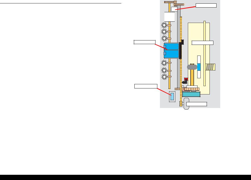
2.1.1.1 Printer Mechanism
The printer mechanism comprises the Carriage carrying the print head, the CR Motor for driving the carriage in the lateral direction in the printing range, the Capping Unit for preventing the print head from drying, the PF Motor for transporting the paper, the ASF Unit for loading paper by the driving force from the PF motor, and the Paper Eject Unit for ejecting the paper after printing.
Paper |
Eject |
Unit |
Print Head
Capping Unit
PF Motor
ASF Mechanism
CR Motor
Figure 2-1. Outline of Printer Mechanism
Operating Principles |
Overview |
14 |
EPSON Stylus CX3100/3200 |
Revision A |
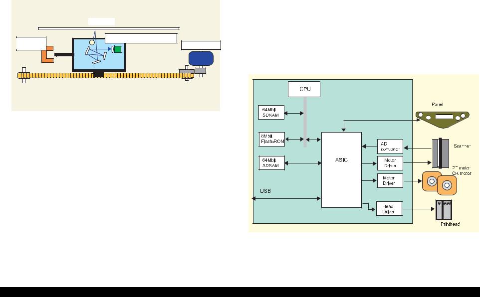
2.1.1.2 Scanner Mechanism |
|
2.1.2 |
Electric Circuit |
||
The scanner consists of the Scanner Carriage Unit comprising the CCD for capturing |
The electric circuit boards of Stylus CX3100/3200 are as follows: |
||||
images and the light source for illuminating the document, the Scanner Motor and |
C497MAIN Board (main circuit board) |
||||
Timing Belt for moving the scanner carriage unit along the document surface, and the |
|||||
|
|
|
|||
Scan HP Detector for detecting the position of the scanner carriage unit. |
C497PSB/C497PSE Board (power supply circuit board) |
||||
|
|
This circuit board supplies the following voltages: |
|||
Document |
|
|
+3.3V: |
For logic |
|
|
|
+42V: |
Driving power |
||
|
|
||||
Scanner HP |
Scanner Carriage Unit |
|
+12V: |
Power to the scanner |
|
Scanner Motor |
|
|
|
||
Detector |
Scanner circuit board |
||||
|
|
||||
|
|
Panel circuit board |
|||
Figure 2-2. Scanner Mechanism
Figure 2-3. Electric Circuit Block
Operating Principles |
Overview |
15 |

EPSON Stylus CX3100/3200 |
Revision A |
Table 2-1. Functions of Major Elements - C497MAIN
Location |
Name |
|
Description |
|
|
|
CPU |
||
|
|
• Built-in RAM 10kB, |
||
IC1 |
C90A20** |
|
Built-in Flash ROM 256KB |
|
• |
144-pin, LQFP, |
|||
|
|
|||
|
|
|
Driving frequency: 48MHz |
|
|
|
• Control, image processing C90A20 |
||
|
|
|
||
IC5 |
MBM29LV800BC-PFTN |
64Mbit Flash ROM |
||
or the equivalent |
• |
Stores firmware |
||
|
||||
|
|
ASIC |
||
|
|
• |
Motor control |
|
IC2 |
E05C08** |
• |
Head control |
|
|
|
• Panel sensor input and output control |
||
|
|
• |
USB I/F |
|
|
|
|
|
|
|
|
• |
EEPROM |
|
|
|
• Storage of default setting and backup of |
||
IC4 |
RTC9822 |
|
various parameters |
|
|
|
• |
Reset function |
|
|
|
• |
Timer function |
|
IC7 |
A6615 |
CR Motor driver |
||
|
|
|
||
IC11 |
LB11847 |
Scanner motor driver |
||
IC6 |
E09A29LA |
Head drive control IC |
||
• |
Supplies COMMON+42 V |
|||
|
|
|||
|
|
|
||
IC8 |
K4S641632D |
16Mbit SDRAM |
||
• |
System memory |
|||
|
|
|||
IC9 |
K4S641632D |
16Mbit SDRAM |
||
• Work area for copy functions |
||||
|
|
|||
|
|
|
|
|
Operating Principles |
Overview |
16 |

C H A P T E R
3
TROUBLESHOOTING
EPSON Stylus CX3100/3200 |
Revision A |
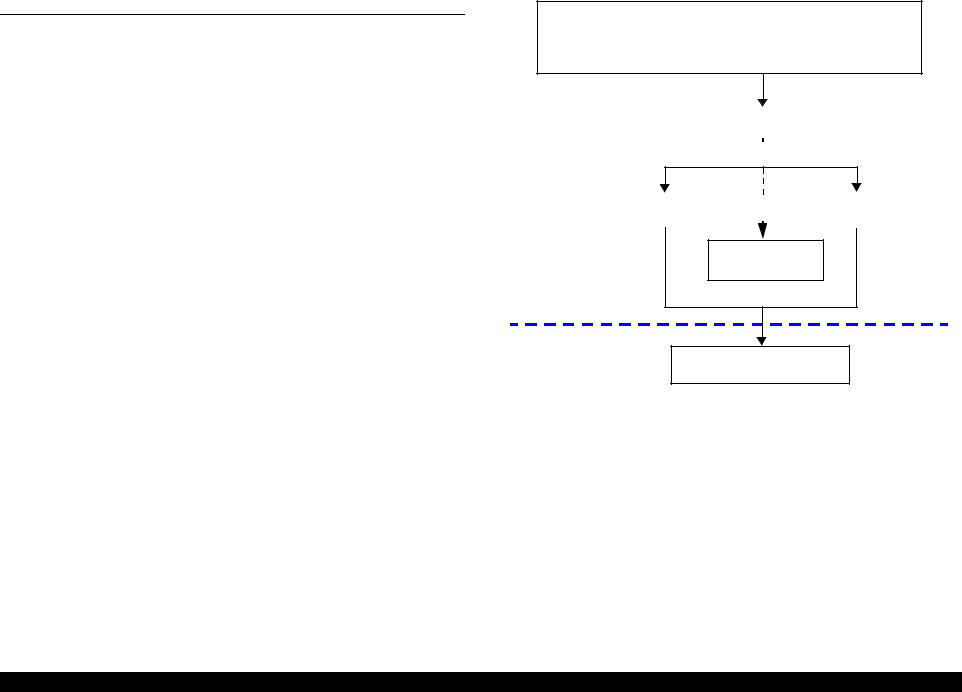
3.1 Troubleshooting at Unit Level
By following this troubleshooting procedure, when some trouble has occurred, you can easily identify the unit which is the cause of the trouble, from its observation. Table 3-1 and Table 3-2 list the observations of various troubles. Once the type of the trouble has been identified, refer to the flowchart for that trouble.
The flowchart shown in Figure 3-1 outlines the troubleshooting procedure.
NOTE: See page 33 for troubleshooting for motors and sensors.
Identifying the Trouble
Table 3-1 "LCD Indication"
Table 3-2 "Observations and Troubleshooting Flowcharts"
|
|
|
|
|
|
|
|
|
|
|
|
|
|
|
|
|
|
|
|
|
|
|
|
|
|
|
|
|
|
|
|
|
|
|
|
|
|
|
|
|
|
|
|
|
|
|
|
|
|
Repair at Unit Level |
|
|
|
|
|
|
|
|
|
|
|
|
|
|
|
|
|
|
|
|
|
|
|
|
|
|
|
|
|
|
|
|
|||||||||||||||
|
|
Diagnosing the Following Units |
|
|
|
|
|
|
|
|
|
|
|
|||||||||||||||||||||||||||||||||||
|
|
|
|
|
|
|
|
|
|
|
|
|
|
|
|
|
|
|
|
|
|
|
|
|
|
|
|
|
|
|
|
|
|
|
|
|
|
|
|
|
|
|
|
|
|
|
|
|
|
|
|
|
|
|
|
|
|
|
|
|
|
|
|
|
|
|
|
|
|
|
|
|
|
|
|
|
|
|
|
|
|
|
|
|
|
|
|
|
|
|
|
|
|
|
|
|
|
|
|
|
|
|
|
|
|
|
|
|
|
|
|
|
|
|
|
|
|
|
|
|
|
|
|
|
|
|
|
|
|
|
|
|
|
|
|
|
|
|
|
|
|
|
|
|
|
|
Repair at Parts
Level |
Printer Mechanism |
|
|
Scanner Mechanism |
|
|
|||
|
|
|||
|
|
|
|
|
|
|
|
|
|
Motor and Sensor
Repair
Disassembly = Chapter 4
Adjustment = Chapter 5
Figure 3-1. Troubleshooting Flowchart
Troubleshooting |
Troubleshooting at Unit Level |
18 |

EPSON Stylus CX3100/3200 |
Revision A |
Table 3-1. LCD Indication
|
|
LCD Indication |
LED Indication |
|
||
Error Status |
(The upper line shows “Error indication” and the |
|
|
Restoration Method |
||
|
lower line shows descriptive character strings by |
|
|
|||
|
|
Power |
Error LED |
|
||
|
|
scrolling.) |
|
|||
|
|
|
|
|
||
|
|
|
|
|
||
Paper out |
Paper out → Load paper in Paper tray and press the |
- |
Lighting up |
Supply paper and press the Color or B&W copy button. |
||
|
Color copy button. |
|
|
|||
|
|
|
|
|
||
|
|
|
|
|
|
|
Paper jam |
Paper jam or miss feed → |
Press the Color copy |
- |
Lighting up |
Remove the jammed paper and press the Color or B&W copy |
|
|
button and clear the paper jam by hand if necessary. |
button. |
||||
|
|
|
||||
Ink cartridge out / Ink end (black) |
• |
No black ink cartridge → |
Press the Color copy |
|
|
Move the carriage to the position for replacement by means of |
|
|
button to install new ink cartridge. |
- |
Lighting up |
the Color or B&W copy button and replace the black ink |
|
|
• |
Black ink out → Press the Color copy button to |
cartridge with a new one. |
|||
|
|
begin replacing the ink cartridge. |
|
|
After replacement, close the scanner unit, and the carriage will |
|
|
|
|
|
|
|
move the printing start position and start printing. |
|
|
|
|
|
|
|
Ink cartridge out / Ink end (color) |
• |
No Color ink cartridge → |
Press the Color copy |
|
|
Move the carriage to the position for replacement by means of |
|
|
button to install new ink cartridge. |
- |
Lighting up |
the Color or B&W copy button and replace the color ink |
|
|
• |
Color ink out → Press the Color copy button to |
cartridge with a new one. |
|||
|
|
begin replacing the ink cartridge. |
|
|
After replacement, close the scanner unit, and the carriage will |
|
|
|
|
|
|
|
move the printing start position and start printing. |
Waste ink overflow |
Printer error → See your documentation and call |
- |
Blinking |
Reset the waste ink counter after replacing the waste ink porous |
||
|
service if necessary. |
|
pad. |
|||
|
|
|
|
|||
|
|
|
|
|
||
Fatal error |
Printer error → See your documentation and call |
- |
Lighting up |
Turn the power off once and turn it on again. If this turning the |
||
|
service if necessary. |
|
power off and on does not work to recover the printer, make |
|||
|
|
|
|
|
|
repairs. |
|
Scanner error → See your documentation and call |
- |
Lighting up |
Turn the power off once and turn it on again. If this turning the |
||
|
service if necessary. |
|
power off and on does not work to cover the scanner, make |
|||
|
|
|
|
|
|
repairs. (Refer to “Troubleshooting for Scanner” (p.30). |
Scanner unit open |
Scanner unit open → Close the scanner unit. |
Blinking |
Lighting up |
Close the scanner unit. |
||
|
|
|
|
|
|
|
Troubleshooting |
Troubleshooting at Unit Level |
19 |
EPSON Stylus CX3100/3200 |
Revision A |
Table 3-2. Observations and Troubleshooting Flowcharts
Observation |
Details |
Refer to |
Power is on but not |
LED does not turn on at all. |
Flowchart 3-1 |
operating |
Printer mechanism does not operate at all. |
|
|
Scanner mechanism does not operate at |
|
|
all. |
|
|
|
|
Error is detected |
LCD/LED panel shows error status. |
Flowchart 3-2 |
Trouble related to |
Printing is not done. |
Flowchart 3-3 |
Print is abnormal (Dot missing, etc.). |
|
|
|
Print quality is bad. |
|
|
|
|
Paper feeding is not |
Paper feeding is not done. |
Flowchart 3-4 |
normally carried out. |
Paper jam occurs. |
|
|
Paper start up position is not correct. |
|
Faulty operation |
Pressing a button does not work. |
Flowchart 3-5 |
panel |
|
|
|
|
|
Trouble related to |
Scanner does not operate normally. |
Refer to |
scanner |
|
“Troubleshooting for |
|
|
Scanner” (p.30) |
|
|
|
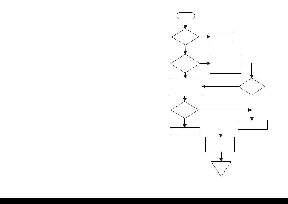
3.1.1Printer / Scanner does not operate at all even with power turned on
Start
AC power / |
No |
voltage |
|
is normal? |
|
Yes |
|
Yes
Fuse (F1) of power board is blown?
Input normal power.
Replace fuse. Disconnect CN10 of main board and turn power on again.
No
No
Check output voltage of
power board CN2. Fuse is blown again?
Yes
No
Power board output voltage is normal?
Yes
Replace power board
Replace main board
Check motors, head and other parts
End
Flowchart 3-1.
Troubleshooting |
Troubleshooting at Unit Level |
20 |

EPSON Stylus CX3100/3200 Revision A
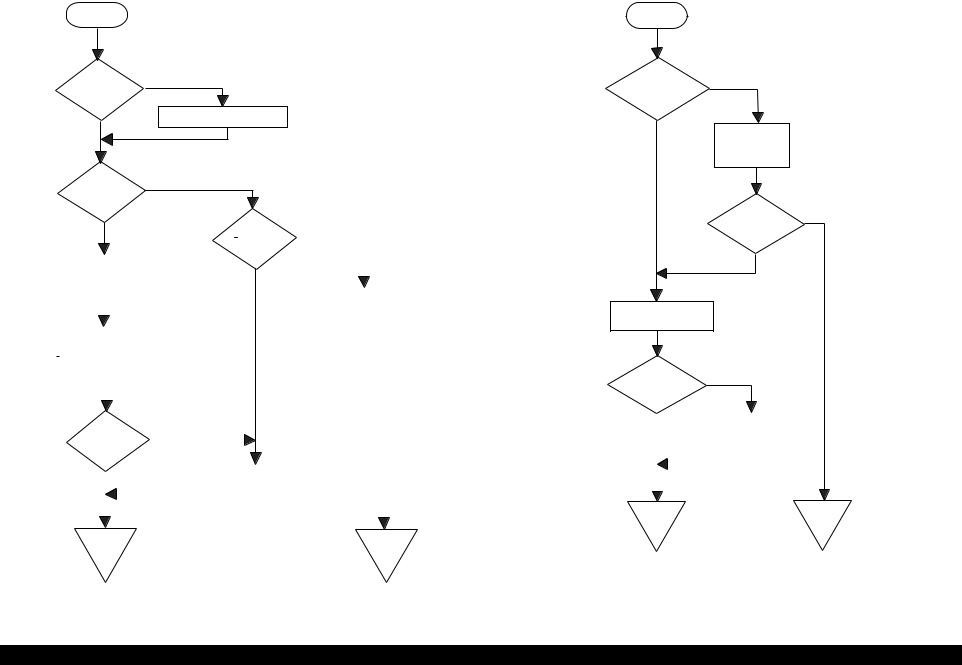
3.1.2 Error is detected |
3.1.3 Trouble related to Print |
|
|
Start |
|
Start |
|
|
|
|
|
|
|
|
Check error contents by LCD (See Table 3-1).
Execute test printing
No
|
|
|
|
Printing was |
|
|
|
|
Yes |
|
|
|
successfully |
|
|
|
|
|
|
|
done? |
|
|
|
|
|
|
|
Turn power off, unlock |
|
Yes |
|
|
|
|
Printer error? |
|
CR and move CR with |
|
|
|
All the cables |
Yes |
|
|
|
hand. |
|
|
Yes |
|
||
|
|
|
|
|
|
are connected |
|
|
No |
|
|
|
|
Execute print |
|
properly to main |
|
|
|
No |
Print quality |
|
board? |
|
||
|
|
|
is normal? |
adjustment (Refer to |
|
No |
|
|
Yes |
|
|
|
“Adjustment” on |
|
|
||
Replace Ink cartridge |
CR cartridge can |
No |
page 57) |
|
|
|
||
Ink cartridge out |
|
with a new one by |
move smoothly? |
|
|
Connect correctly |
||
|
operation panel. |
|
|
|
|
|||
error? |
|
|
Yes |
Execute cleaning |
|
|
|
|
No |
|
|
|
|
|
|
No |
|
|
|
|
|
|
|
|
||
|
|
|
|
|
No |
|
|
|
|
|
|
Check CR motor and if |
|
|
Problem is |
Refer to Table 3-5 |
|
Maintenance error |
No |
|
Problem is |
Replace Ink cartridge |
solved? |
|||
Ink cartridge out |
there is no problem, |
solved? |
|
|
||||
|
|
replace main board. |
|
and execute test print. |
Yes |
|
||
|
|
error is cleared? |
|
Yes |
|
|
|
|
|
|
|
|
|
|
|
No |
|
|
|
|
|
|
|
|
|
|
Replace waste ink porous |
|
Yes |
|
|
Yes |
|
|
Problem is |
pad and reset counter. |
|
Yes |
|
|
|
solved? |
||
(Refer to “Disassembly and |
|
|
Carriage smoothly |
|
Problem is |
|
|
|
Assembly” on page 34 and |
|
|
|
solved? |
|
|
Yes |
|
|
|
moves? |
|
|
|
|
||
“Adjustment” on page 57) |
|
|
|
|
No |
|
|
|
|
|
|
No |
|
|
|
|
|
|
|
|
|
|
|
|
|
|
Check whether Head |
|
|
Refer to Table 3-5 |
|
Replace main board |
|||
Refer to Table 3-5 |
|
|
|
|||||
FFC is connected |
|
|
|
|
||||
|
|
|
|
|
|
|||
properly to head. |
|
|
|
|
|
|
|
|
|
|
|
|
|
Yes |
No |
|
|
|
|
|
|
|
Problem is |
|
|
|
|
|
|
|
|
solved? |
|
|
|
|
|
End |
End |
End |
|
|
End |
End |
|
|
|
|
|
|
|||
Flowchart 3-2. |
Flowchart 3-3. |
Troubleshooting |
Troubleshooting at Unit Level |
21 |
Stylus Photo 720 |
Revision B |
3.1.4 Paper feeding is not normally carried out
Start
No
Paper is correctly set in ASF?
Set paper correctly.
Yes
No
Paper loading roller and PF roller are correctly
rotating?
No
Yes |
|
|
PF motor is |
||||||||
|
|
|
|
|
driving? |
|
|
|
|
||
|
|
|
|
|
|
|
|
|
|
|
|
Remove foreign matters, |
|
|
Yes |
|
|
||||||
if any, from paper route. |
|
|
|
|
|||||||
|
|
|
|
|
|
|
|
|
|
|
|
|
|
|
|
|
|
|
|
|
Check whether connector |
||
|
|
|
|
||||||||
|
|
|
|
|
|
|
|
|
of PF motor is connected |
||
|
|
|
|
|
|
|
|
|
to CN7 of main board. If |
||
Clean rollers on paper |
|
|
|
|
|
|
it is connected properly, |
||||
|
|
|
|
|
|
replace main board. |
|||||
route. (Refer to |
|
|
|
|
|
|
|||||
“Maintenance” on |
|
|
|
|
|
|
|
|
|
||
page 74) |
|
|
|
|
|
|
|
|
|
||
|
|
|
|
|
|
|
|
|
|||
|
|
|
|
|
|
|
|
|
|
|
|
|
|
|
No |
|
|||||||
Problem is |
|
||||||||||
|
|
|
|
|
|
|
|
|
|||
solved? |
|
|
|
|
|
|
|
|
|
|
|
|
|
|
|
|
|
|
|
|
|
|
|
|
|
|
|
|
|
|
|
|
|
|
|
Yes |
|
|
|
|
Refer to Table 3-5 |
|
|
|
|||
|
|
|
|
|
|
|
|
|
|
|
|
|
|
|
|
|
|
|
|
|
|
|
|
|
|
|
|
|
|
|
|
|
|
|
|
End |
|
|
|
|
|
|
|
End |
|||
Flowchart 3-4.
3.1.5 Operation Panel faulty
Start
Operation Panel is connected
properly with No cable?
Yes
Connectcorrectly Operation panel again.
Yes
Problem is solved?
No
Replace operation panel.
No
Problem is solved?
Yes |
|
Replace main |
|
|
|
board. |
|
|
|
|
|
|
|
|
|
|
|
|
|
End |
End |
Flowchart 3-5.
Troubleshooting |
Troubleshooting at Unit Level |
22 |

EPSON Stylus CX3100/3200 |
Revision A |
3.2 Troubleshooting for Printer
This section describes repair / service of the Printer Mechanism. Listed below are various problems which may occur, observations of such problems, check point and remedies. For the pertinent observation, check the functions of the parts in question according to Check Point.
Table 3-3. Printer Errors
Observation |
Cause |
Remedy |
Ink shortage / |
• If any ink cartridge comes |
• Start cleaning execution command on |
Ink out |
close to Ink out, Printer |
Panel or by Utility. |
|
continues printing in ink |
• Carriage automatically moves to |
|
shortage status. |
replacement position. |
|
• If cartridge is completely |
• Replace ink cartridge with a new one. |
|
empty, Printer indicates ink |
|
|
out error and stop printing. |
|
|
|
|
Paper out |
• When Printer cannot load |
(1)Set paper on tray if paper is out. |
|
paper, paper out error is |
(2)If paper is stopped midway, pull paper |
|
indicated. |
out and check that paper is not folded. |
|
• Paper stops in front of PE |
Loosen paper well and set it again with |
|
detector or paper is not |
edge guide adjusted to paper width. |
|
loaded. |
(3)Execute “Load/Eject”. |
|
• Paper is loaded without |
• Clean paper loading roller. Or replace |
|
adjusting paper to right |
paper loading roller. |
|
edge guide. |
• Check that gears for ASF are engaged |
|
|
|
|
|
correctly. |
|
|
|
|
|
Table 3-3. Printer Errors |
(continued) |
|
|
|
|
|
|
Observation |
|
Cause |
|
Remedy |
|
|
|
|
|
Paper jam |
|
When paper is not ejected, |
• Select “Load/Eject” from menu and |
|
|
paper jam error is indicated. |
|
execute it. |
|
|
|
|
(1)Open the printer cover and remove |
|
|
|
|
|
with hand all the paper inside the |
|
|
|
|
printer and all the set paper if there is |
|
|
|
|
paper on the way of loading. |
|
|
|
(2)Check that there is no paper in the |
|
|
|
|
|
printer and set paper again and execute |
|
|
|
|
paper loading and paper ejection. |
|
|
|
|
Then, this error display will be cleared |
|
|
|
|
and if there is print data, print |
|
|
|
|
operation will start. |
|
|
|
• Check whether Platen gap is correct |
|
|
|
|
|
value. (Refer to “Adjustment” on |
|
|
|
|
page 57) |
Ink cartridge out |
• If Ink cartridge is not |
• Check CSIC connection circuit. |
||
|
|
correctly set, printer |
• |
Replace ink cartridge. |
|
|
indicates ink cartridge out |
|
|
|
|
error. |
|
|
Maintenance |
Waste ink overflow |
After replacing waste ink porous pad, |
||
error |
indication is displayed if the |
reset waste ink overflow counter. (Refer |
||
|
total amount of ink |
to “Protection Counter” on page 69) |
||
|
consumed by cleaning and/or |
|
|
|
|
flushing has exceeded the |
|
|
|
|
predetermined limit. |
|
|
|
|
|
|
|
|
Fatal error |
• |
Carriage error: |
• Several seconds or more after turning |
|
|
• Home of carriage can not |
|
power off, press power switch to turn |
|
|
|
be recognized. |
|
power on. |
|
• |
Abnormal external power |
• Open maintenance cover and check |
|
|
|
was applied to carriage or |
|
that there is no obstacle in the carriage |
|
|
carriage operation is |
|
moving zone. |
|
|
obstructed during printing. |
If the error is not cleared even by the |
|
|
• |
PF error: |
above operation, check the followings: |
|
|
PF motor does not operate |
• |
CR HP sensor/Harness |
|
|
adequately to feed paper by |
• |
CR Lock mechanism |
|
|
the required distance. |
• |
Main board |
|
Troubleshooting |
Troubleshooting for Printer |
23 |

EPSON Stylus CX3100/3200 |
|
|
|
Revision A |
|||
|
|
|
|
Table 3-4. Printer Mechanism Repair |
|
|
|
|
|
|
|
|
|
|
|
|
Observation |
Condition |
Cause |
Check Point |
Remedy |
|
|
|
|
|
|
|
|
|
|
|
Faulty pump mechanism |
|
When power is turned on, |
There are foreign matters on |
Operate the platen drive gear by hand and check |
Remove foreign matters. |
|
|
|
|
PF motor operation is |
the PF gear. |
whether it rotates properly. |
Replace the printer mechanism. |
|
|
|
|
abnormal. |
|
|
|
|
|
|
|
PF motor is faulty. |
Check whether the internal coil resistance is just |
Replace the printer mechanism or PF |
|
|
|
|
|
|
|
|||
|
|
|
|
|
as specified and whether the harness is connected |
motor. |
|
|
|
|
|
|
properly. See Table 3-13, “Motor Resistance and |
|
|
|
|
|
|
|
Check Point,” on page 33. |
|
|
|
|
|
|
|
|
|
|
|
Ink is not absorbed at all |
|
Ejected ink does not flow |
Pump tube is crashed. |
Check tube with the naked eye. |
Replace the printer mechanism or pump |
|
|
or ink absorption is poor. |
|
into Ink Eject tube. |
|
|
unit. |
|
|
|
|
|
|
|
|
|
|
|
|
|
Capping unit is faulty. |
Check capping rubber with the naked eye. |
Replace the printer mechanism or |
|
|
|
|
|
|
|
capping unit. |
|
|
|
|
|
|
|
|
|
|
|
|
|
Tube is projecting from cap. |
Check with the naked eye whether tube is |
Connect the tube correctly. |
|
|
|
|
|
|
projecting from cap. |
|
|
|
|
|
|
|
|
|
|
|
|
|
|
Pump tube is entangled in the |
When cap assembly slides up completely, check |
Remove the entangled pump tube |
|
|
|
|
|
pump unit. |
whether there is a small slack in pump tube |
carefully, correct the tube condition and |
|
|
|
|
|
|
between cap assembly and pump unit. |
connect it to the cap assembly. |
|
|
|
|
|
|
|
|
|
|
|
|
Ink is not absorbed from |
Dirt on cap |
Check whether any foreign matter is adhering to |
Remove foreign matters from the cap |
|
|
|
|
head to cap. |
|
cap. |
and if the cap is damaged, replace it |
|
|
|
|
|
|
|
with a new one. |
|
|
|
|
|
|
|
|
|
|
|
|
|
Faulty slide-up of cap |
Check whether two compression springs are set |
Set the compression springs on the cap |
|
|
|
|
|
|
on cap assembly. |
assembly. |
|
|
|
|
|
|
|
|
|
Troubleshooting |
Troubleshooting for Printer |
24 |

EPSON Stylus CX3100/3200 |
|
|
|
Revision A |
|||
|
|
|
|
Table 3-4. Printer Mechanism Repair (continued) |
|
|
|
|
|
|
|
|
|
|
|
|
Observation |
Condition |
Cause |
Check Point |
Remedy |
|
|
|
|
|
|
|
|
|
|
|
Faulty carriage operation |
|
When power is turned on, |
There is an obstacle in CR |
Check with the naked eye whether there is an |
Remove the obstacle. |
|
|
|
|
carriage operation is |
shift area. |
obstacle. |
|
|
|
|
|
abnormal. |
|
|
|
|
|
|
|
CR lock is not released. |
Check that change lever is in the front of printer. |
Return the change lever to the back of |
|
|
|
|
|
|
|
|||
|
|
|
|
|
|
printer by tweeters or a small driver. |
|
|
|
|
|
|
|
|
|
|
|
|
|
|
Check whether the CN13 connector and coil |
Connect the PF motor to CN7 on the |
|
|
|
|
|
|
resistance of the PF motor are as specified. See |
main board. |
|
|
|
|
|
|
Table 3-13, “Motor Resistance and Check |
Replace the printer mechanism or PF |
|
|
|
|
|
|
Point,” on page 33. |
motor. |
|
|
|
|
|
|
|
|
|
|
|
|
|
|
Check whether any gear is damaged on the |
Replace the damaged gear with a new |
|
|
|
|
|
|
torque transmission route of PF motor. |
one. |
|
|
|
|
|
|
|
|
|
|
|
|
|
Faulty CR motor |
Check whether the internal coil resistance is just |
Replace the CR motor. |
|
|
|
|
|
|
as specified and whether the harness is connected |
|
|
|
|
|
|
|
properly. See Table 3-13, “Motor Resistance and |
|
|
|
|
|
|
|
Check Point,” on page 33. |
|
|
|
|
|
|
|
|
|
|
|
|
|
Abnormal carriage |
Carriage does not move |
Operate the carriage by hand and check whether |
Clean the CR guide shaft and lubricate. |
|
|
|
|
operation during printing |
smoothly. |
carriage moves smoothly. |
|
|
|
|
|
|
|
|
|
|
|
|
|
|
|
Check tension of timing belt. |
Adjust tension or replace the belt. |
|
|
|
|
|
|
|
|
|
|
|
|
|
|
Check whether there is an obstacle in carriage |
Remove the obstacle. |
|
|
|
|
|
|
route. |
|
|
|
|
|
|
|
|
|
|
|
Printing is not carried out |
|
Carriage moves correctly |
Head FFC is not connected |
Check whether Head FFC is connected properly |
Connect the FFC correctly. |
|
|
correctly. |
|
but printing is not normal. |
properly. |
to CN8 and CN9 of main board. |
|
|
|
|
|
|
|
|
|
|
|
|
|
|
Inside of FFC is not |
Check FFC by tester. |
Replace the FFC. |
|
|
|
|
|
connected properly. |
|
|
|
|
|
|
|
|
|
|
|
|
|
|
|
Faulty ink cartridge |
Set new ink cartridge and execute test printing. |
Replace the ink cartridge. |
|
|
|
|
|
|
|
|
|
|
|
|
|
Faulty head unit |
Repeat cleaning and test printing alternately |
Replace the head unit. |
|
|
|
|
|
|
several times. |
|
|
|
|
|
|
|
|
|
|
|
|
|
|
Faulty head cleaner |
Check whether dust is adhering to head cleaner. |
Clean or replace the head cleaner. |
|
|
|
|
|
|
|
|
|
Troubleshooting |
Troubleshooting for Printer |
25 |

EPSON Stylus CX3100/3200 |
|
|
|
Revision A |
|||
|
|
|
|
Table 3-4. Printer Mechanism Repair (continued) |
|
|
|
|
|
|
|
|
|
|
|
|
Observation |
Condition |
Cause |
Check Point |
Remedy |
|
|
|
|
|
|
|
|
|
|
|
Faulty print |
|
Faulty printing occurs at |
Head surface is dirty. |
Repeat cleaning and test printing alternately |
Clean with a swab fixed to a stick. |
|
|
|
|
specific dots. |
(Dot missing occurs) |
several times. |
|
|
|
|
|
|
|
|
|
|
|
|
|
|
Faulty head FFC |
Check whether head FFC is damaged. |
Replace the head FFC with a new one. |
|
|
|
|
|
|
|
|
|
|
|
|
|
Faulty head unit |
Repeat cleaning and nozzle checking alternately |
If the condition is not improved even |
|
|
|
|
|
|
several times. |
after cleaning, replace the head. |
|
|
|
|
|
|
|
|
|
|
|
|
|
Capping porous pad is in |
Check capping porous pad with the naked eye. |
Replace the capping porous pad, if its |
|
|
|
|
|
contact with head surface. |
|
shape is deformed or it is damaged. |
|
|
|
|
|
|
|
|
|
|
|
|
Sometimes dots are |
Head surface is dirty. |
Repeat cleaning and nozzle checking alternately |
Clean with a swab fixed to a stick. |
|
|
|
|
missing. |
(Dot is missing occurs) |
several times. |
|
|
|
|
|
|
|
|
|
|
|
|
|
|
Inside of FFC is not |
Check FFC by tester. |
Replace the head FFC. |
|
|
|
|
|
connected properly. |
|
|
|
|
|
|
|
|
|
|
|
|
|
|
|
Head FFC is not connected. |
Check whether Board and Carriage FFC are |
Connect the FFC correctly. |
|
|
|
|
|
|
connected. |
|
|
|
|
|
|
|
|
|
|
|
|
|
|
Faulty Head unit. |
Execute cleaning several times, and Check |
If the condition is not improved even |
|
|
|
|
|
|
nozzle. |
after cleaning, replace the head. |
|
|
|
|
|
|
|
|
|
|
|
|
|
Faulty ink cartridge. |
Set new ink cartridge and check nozzle. |
Replace the ink cartridge. |
|
|
|
|
|
|
|
|
|
|
|
|
Black points or dots are |
Head FFC is not connected. |
Check whether Board and Carriage FFC are |
Connect the FFC correctly. |
|
|
|
|
printed. |
|
connected. |
|
|
|
|
|
|
|
|
|
|
|
|
|
|
Faulty head unit |
Check connection with head FFC. |
If connection with the FFC is not faulty, |
|
|
|
|
|
|
|
replace the head. |
|
|
|
|
|
|
|
|
|
Troubleshooting |
Troubleshooting for Printer |
26 |

EPSON Stylus CX3100/3200 |
|
|
|
|
Revision A |
|||
|
|
|
|
Table 3-4. Printer Mechanism Repair (continued) |
|
|
||
|
|
|
|
|
|
|
|
|
|
Observation |
Condition |
Cause |
|
Check Point |
Remedy |
|
|
|
|
|
|
|
|
|
|
|
|
Faulty print |
|
Vertical line is not |
Bi-D adjustment has not been |
Make Bi-D adjustment. |
Refer to “Adjustment” (p.57) |
|
|
|
|
|
straightly lined. |
made. |
|
|
|
|
|
|
|
|
|
|
|
|
|
|
|
|
White line appears in |
Dirt is adhering to CR guide |
Check whether dirt is adhering to the surface of |
Clean the surface of CR guide shaft with |
|
|
|
|
|
output data. |
shaft. |
CR guide shaft. |
a dry and soft cloth. |
|
|
|
|
|
|
|
|
|
|
|
|
|
|
|
Faulty CR guide shaft. |
Check that CR guide shaft is steadily installed in |
Reinstall the CR guide shaft on the |
|
|
|
|
|
|
|
the designated position. |
mounting slats (wing boards) on both |
|
|
|
|
|
|
|
Check that CR guide shaft surface is flat. |
sides of the frame, and fix it with the rod |
|
|
|
|
|
|
|
|
|
spring. |
|
|
|
|
|
|
|
|
Replace the CR guide shaft with a new |
|
|
|
|
|
|
|
|
one. |
|
|
|
|
|
|
|
|
|
|
|
|
|
|
Faulty slide operation of |
Check whether sufficient oil is remaining on the |
Clean the surface in the carriage slide |
|
|
|
|
|
|
Carriage. |
surface in the carriage slide area on the Paper |
area and apply a specified amount of G- |
|
|
|
|
|
|
|
Eject Frame. |
26. (Refer to “Maintenance” (p.74)) |
|
|
|
|
|
|
|
|
|
|
|
|
|
|
|
Paper feeding route is dirty. |
Check whether PF roller is dirty. |
Clean the surface of the PF roller |
|
|
|
|
|
|
|
|
|
carefully with a soft brush. |
|
|
|
|
|
|
|
|
|
|
|
|
|
|
Damaged gear |
Check whether the following parts are not |
Replace the damaged part with a new |
|
|
|
|
|
|
|
damaged. |
one. |
|
|
|
|
|
|
|
• |
Combination gear16, 21.6 |
|
|
|
|
|
|
|
• Combination gear 11.6, 36.8 |
|
|
|
|
|
|
|
|
• |
Spur gear 73.6 |
|
|
|
|
|
|
|
• |
Spur gear 25.6 |
|
|
|
|
|
|
|
|
|
|
|
|
|
|
|
Platen gap is not correct. |
Adjust platen gap. |
Refer to “Adjustment” (p.57) |
|
|
|
|
|
|
|
|
|
|
|
|
|
|
|
As head surface is dirty, dot |
Repeat cleaning and test printing alternately |
Clean with a swab fixed to a stick. |
|
|
|
|
|
|
jet direction is slanting. |
several times. |
|
|
|
|
|
|
|
|
|
|
|
|
|
|
|
|
|
Check whether dust is adhering to head cleaner. |
Clean or replace the head cleaner. |
|
|
|
|
|
|
|
|
|
|
|
|
|
|
|
Faulty ink cartridge |
Set new ink cartridge and execute test printing. |
Replace the ink cartridge. |
|
|
|
|
|
|
|
|
|
|
|
|
|
|
|
Faulty head unit |
Clean several times, and execute test printing. |
Replace the head unit. |
|
|
|
|
|
|
|
|
|
|
|
Troubleshooting |
Troubleshooting for Printer |
27 |
Loading...