


 Loading...
Epson Stylus C58, Stylus C59, Stylus C79, Stylus D78, Stylus C90 Service Manual
...SERVICE MANUAL
Color Inkjet Printer
Epson Stylus C58/C59
Epson ME 2
Epson Stylus C79/D78
Epson Stylus C90/C91/C92/D92
Epson Stylus T20/T20E/T23/T26/S20
Epson Stylus T10/T11
Epson ME 30
Epson Stylus T21/T24/T27/S21
Notice:
All rights reserved. No part of this manual may be reproduced, stored in a retrieval system, or transmitted in any form or by any means, electronic, mechanical, photocopying, recording, or otherwise, without the prior written permission of SEIKO EPSON CORPORATION.
The contents of this manual are subject to change without notice.
All effort have been made to ensure the accuracy of the contents of this manual. However, should any errors be detected, SEIKO EPSON would greatly appreciate being informed of them.
The above not withstanding, SEIKO EPSON CORPORATION can assume no responsibility for any errors in this manual or the consequences thereof.
EPSON is a registered trademark of SEIKO EPSON CORPORATION.
General Notice: |
Other product names used herein are for identification purpose only and may be trademarks or registered trademarks of their |
|
respective owners. EPSON disclaims any and all rights in those marks. |
Copyright © 2009 SEIKO EPSON CORPORATION.
IJP LP CS Quality Assurance Department
|
PRECAUTIONS |
Precautionary notations throughout the text are categorized relative to 1) personal injury and 2) damage to equipment. |
|
DANGER |
Signals a precaution which, if ignored, could result in serious or fatal personal injury. Great caution should be exercised in performing procedures preceded by |
|
DANGER Headings. |
WARNING |
Signals a precaution which, if ignored, could result in damage to equipment. |
The precautionary measures itemized below should always be observed when performing repair/maintenance procedures.
DANGER
1.ALWAYS DISCONNECT THE PRODUCT FROM THE POWER SOURCE AND PERIPHERAL DEVICES PERFORMING ANY MAINTENANCE OR REPAIR PROCEDURES.
2.NO WORK SHOULD BE PERFORMED ON THE UNIT BY PERSONS UNFAMILIAR WITH BASIC SAFETY MEASURES AS DICTATED FOR ALL ELECTRONICS TECHNICIANS IN THEIR LINE OF WORK.
3.WHEN PERFORMING TESTING AS DICTATED WITHIN THIS MANUAL, DO NOT CONNECT THE UNIT TO A POWER SOURCE UNTIL INSTRUCTED TO DO SO. WHEN THE POWER SUPPLY CABLE MUST BE CONNECTED, USE EXTREME CAUTION IN WORKING ON POWER SUPPLY AND OTHER ELECTRONIC COMPONENTS.
4.WHEN DISASSEMBLING OR ASSEMBLING A PRODUCT, MAKE SURE TO WEAR GLOVES TO AVOID INJURY FROM METAL PARTS WITH SHARP EDGES.
WARNING
1.REPAIRS ON EPSON PRODUCT SHOULD BE PERFORMED ONLY BY AN EPSON CERTIFIED REPAIR TECHNICIAN.
2.MAKE CERTAIN THAT THE SOURCE VOLTAGE IS THE SAME AS THE RATED VOLTAGE, LISTED ON THE SERIAL NUMBER/RATING PLATE. IF THE EPSON PRODUCT HAS A PRIMARY AC RATING DIFFERENT FROM AVAILABLE POWER SOURCE, DO NOT CONNECT IT TO THE POWER SOURCE.
3.ALWAYS VERIFY THAT THE EPSON PRODUCT HAS BEEN DISCONNECTED FROM THE POWER SOURCE BEFORE REMOVING OR REPLACING PRINTED CIRCUIT BOARDS AND/OR INDIVIDUAL CHIPS.
4.IN ORDER TO PROTECT SENSITIVE MICROPROCESSORS AND CIRCUITRY, USE STATIC DISCHARGE EQUIPMENT, SUCH AS ANTI-STATIC WRIST STRAPS, WHEN ACCESSING INTERNAL COMPONENTS.
5.REPLACE MALFUNCTIONING COMPONENTS ONLY WITH THOSE COMPONENTS BY THE MANUFACTURE; INTRODUCTION OF SECOND-SOURCE ICs OR OTHER NON-APPROVED COMPONENTS MAY DAMAGE THE PRODUCT AND VOID ANY APPLICABLE EPSON WARRANTY.
6.WHEN USING COMPRESSED AIR PRODUCTS; SUCH AS AIR DUSTER, FOR CLEANING DURING REPAIR AND MAINTENANCE, THE USE OF SUCH PRODUCTS CONTAINING FLAMMABLE GAS IS PROHIBITED.
About This Manual
This manual describes basic functions, theory of electrical and mechanical operations, maintenance, and repair procedures of the printer.
The instructions and procedures included herein are intended for experienced repair technicians, and attention should be given to the precautions on the preceding page.
Manual Configuration
This manual consists of six chapters and Appendix.
CHAPTER 1.PRODUCT DESCRIPTIONS
Provides a general overview and specifications of the product.
CHAPTER 2.OPERATING PRINCIPLES
Describes the theory of electrical and mechanical operations of the product.
CHAPTER 3.TROUBLESHOOTING
Describes the step-by-step procedures for the troubleshooting.
CHAPTER 4.DISASSEMBLY / ASSEMBLY
Describes the step-by-step procedures for disassembling and assembling the product.
CHAPTER 5.ADJUSTMENT
Provides Epson-approved methods for adjustment.
CHAPTER 6.MAINTENANCE
Provides preventive maintenance procedures and the list of Epsonapproved lubricants and adhesives required for servicing the product.
APPENDIX Provides the following additional information for reference:
• Exploded Diagram
Symbols Used in this Manual
Various symbols are used throughout this manual either to provide additional information on a specific topic or to warn of possible danger present during a procedure or an action. Be aware of all symbols when they are used, and always read NOTE, CAUTION, and WARNING messages.
Indicates an operating or maintenance procedure, practice or condition WARNING that, if not strictly observed, could result in injury.
CAUTION |
Indicates an operating or maintenance procedure, practice, or condition |
|
that, if not strictly observed, could result in damage to, or destruction of, |
||
|
equipment. |
|
CHECK |
May indicate an operating or maintenance procedure, practice or |
|
condition that is necessary to accomplish a task efficiently. It may also |
||
POINT |
||
|
provide additional information that is related to a specific subject, or |
|
|
comment on the results achieved through a previous action. |
|
ADJUSTMENT |
Indicates an operating or maintenance procedure, practice or condition |
|
REQUIRED |
that is necessary to maintain the product’s quality. |
|
|
Indicates that a particular task must be carried out according to a certain |
|
|
standard after disassembly and before re-assembly, otherwise the |
|
|
quality of the components in question may be adversely affected. |

|
|
Revision Status |
Revision |
Date of Issue |
Description |
A |
August 7, 2006 |
First Release |
B |
December 1, 2006 |
[Chapter 4] |
|
|
• “4.3.1 Upper Housing (p38)” |
|
|
Note when replacing the Base Frame is added to the reassembly procedure. |
|
|
[Chapter 7] |
|
|
• “7.1 Exploded Diagram / Parts List (p85)” are updated. |
C |
May 1, 2007 |
[All chapters] |
|
|
• The model name; EPSON Stylus C90/C91/C92/D92 are added. |
|
|
[Chapter 1] |
|
|
• “1.2.3 Ink Cartridge (p14)” is updated. |
[Chapter 2]
•“ The Capping mechanism covers the printhead with the cap to prevent the nozzle from increasing viscosity when the printer is in stand-by state or when the printer is off. (p25)” is updated.
[Chapter 4]
•“4.5.6 Ink System removal (p51)”
Caution during inserting the Ink Tube into the connector is added.
•“4.5.8 EJ Frame Assy/EJ Roller (p54)”
Reassembly procedure of the Grounding Spring, Frame is added.
[Chapter 5]
•“5.2.1 Head angular adjustment (p75)”
Print samples made by the adjustment program for Stylus C90/C91/C92/D92 is added.
[Chapter 6]
•“6.1.3 Lubrication (p81)”
Lubrication point for Stylus C90/C91/C92/D92 is added.
[Chapter 7]
•“7.1 Exploded Diagram / Parts List (p85)”
Exploded Diagrams for Stylus C90/C91/C92/D92 are added.
•“7.3 Circuit Diagrams (p96)”
Circuit diagram of Stylus C90/C91/C92/D92; C683 Main is added.

Revision  Date of Issue
  Description
D |
May 16, 2008 |
[All chapters] |
|
|
The model name; Stylus T20/T20E/T23/T26/S20/T10/T11/Me 30 are added. |
|
|
[Chapter 1] |
|
|
• “1.1 Features (p10)” is updated. |
|
|
• “1.2.1 Paper Support (p12)” is updated. |
|
|
• “1.2.3 Ink Cartridge (p14)” is updated. |
|
|
• “1.3.1 USB Interface (p16)” is updated. |
|
|
[Chapter 2] |
|
|
• 2.3 Electrical Circuit Operating Principles is deleted. |
|
|
[Chapter 4] |
|
|
• “4.1.6 Procedural Differences between the Models (p35)” is updated. |
|
|
• “4.2 Disassembly Procedures (p37)” is updated. |
|
|
• “4.5.5 CR Unit/Timing Belt (p48)” |
|
|
Reassembly procedure of the Installing Head FFC is added. |
|
|
[Chapter 7] |
|
|
• Exploded Diagram / Parts List is changed to reference to SPI. |
|
|
• Circuit Diagrams is deleted. |
E |
May 7, 2009 |
[All chapters] |
The model name; Epson Stylus T21/T24/T27/S21 are added.
[Chapter 1]
• “1.1 Features (p10)” is updated.
• “ Print speed & printable width (p11)” is updated.
• “1.2.1 Paper Support (p12)” is updated.
• “1.2.2 Printable Area Size and Margins (p13)” is updated.
• “1.2.3 Ink Cartridge (p14)” is updated.
• “1.2.4 Black Ink Save Mode (p15)” is updated.
• “1.3.1 USB Interface (p16)” is updated.
• “1.4.1 Electrical Specifications (p17)” is updated.
• “1.4.2 Acoustic Noise (p17)” is updated.
• “1.4.3 Safety Approvals (p17)” is updated.
• “1.4.5 Environmental Performance (p18)” is revised.
• “1.4.6 Durability (p18)” is revised.
[Chapter 2]
• “2.3 Power-On Sequence (p26)” is added.

Epson Stylus C58/C59/ME 2/C79/D78/C90/C91/C92/D92/T20/T20E/T23/T26/S20/T10/T11/ME 30/T21/T24/T27/S21 |
Revision E |
Contents
Chapter 1 PRODUCT DESCRIPTION
1.1 |
Features................................................................................................................ |
10 |
||
1.2 |
Printer Specifications. ......................................................................................... |
11 |
||
|
1.2.1 |
Paper Support . ......................................................................................... |
12 |
|
|
1.2.2 |
Printable Area Size and Margins. ............................................................ |
13 |
|
|
1.2.3 |
Ink Cartridge. ........................................................................................... |
14 |
|
|
1.2.4 Black Ink Save Mode . ............................................................................. |
15 |
||
1.3 |
Interface............................................................................................................... |
16 |
||
1.3.1 |
USB Interface . ................................................................................................. |
16 |
||
1.4 |
General Specifications. ....................................................................................... |
17 |
||
1.4.1 |
Electrical Specifications . ................................................................................. |
17 |
||
1.4.2 |
Acoustic Noise. ................................................................................................ |
17 |
||
1.4.3 |
Safety Approvals . ............................................................................................ |
17 |
||
1.4.4 CE Marking . .................................................................................................... |
17 |
|||
1.4.5 Environmental Performance . ........................................................................... |
18 |
|||
1.4.6 |
Durability.......................................................................................................... |
18 |
||
1.5 |
Control Panel . ..................................................................................................... |
19 |
||
|
1.5.1 |
Buttons...................................................................................................... |
19 |
|
|
1.5.2 |
Indicators . ................................................................................................ |
19 |
|
|
1.5.3 |
Errors and Panel Status. ........................................................................... |
20 |
|
|
1.5.4 |
Printer Initialization. ................................................................................ |
20 |
|
Chapter 2 OPERATING PRINCIPLES
2.1 |
Overview ............................................................................................................. |
22 |
2.2 |
Printer Mechanism. ............................................................................................. |
22 |
|
2.2.1 Printhead Specifications . ......................................................................... |
23 |
|
2.2.2 Carriage Mechanism. ............................................................................... |
23 |
|
2.2.3 Paper Feeding Mechanism . ..................................................................... |
24 |
|
2.2.4 Ink System Mechanism . .......................................................................... |
25 |
2.3 |
Power-On Sequence . .......................................................................................... |
26 |
Chapter 3 TROUBLESHOOTING
3.1 |
Overview ............................................................................................................. |
28 |
|
|
3.1.1 |
Specified Tools......................................................................................... |
28 |
|
3.1.2 |
Preliminary Checks . ................................................................................ |
28 |
3.2 |
Troubleshooting With LED Error Indications. ................................................... |
29 |
|
3.3 |
Troubleshooting for Motors and Sensors . .......................................................... |
30 |
|
Chapter 4 DISASSEMBLY/ASSEMBLY
4.1 |
Overview ............................................................................................................. |
32 |
|
|
4.1.1 |
Precautions ............................................................................................... |
32 |
|
4.1.2 |
Tools......................................................................................................... |
33 |
|
4.1.3 |
Screws ...................................................................................................... |
33 |
|
4.1.4 Work Completion Check. ........................................................................ |
34 |
|
|
4.1.5 |
Caution After Repair . .............................................................................. |
34 |
|
4.1.6 |
Procedural Differences between the Models. .......................................... |
35 |
4.2 |
Disassembly Procedures. .................................................................................... |
37 |
|
4.3 |
Removing Housing.............................................................................................. |
38 |
|
4.3.1 Upper Housing . ............................................................................................... |
38 |
||
4.4 |
Removing Board.................................................................................................. |
40 |
|
|
4.4.1 Main Board............................................................................................... |
40 |
|
7 

Epson Stylus C58/C59/ME 2/C79/D78/C90/C91/C92/D92/T20/T20E/T23/T26/S20/T10/T11/ME 30/T21/T24/T27/S21 |
Revision E |
4.5 Disassembling Printer Mechanism . .................................................................... |
42 |
4.5.1 Hopper ...................................................................................................... |
42 |
4.5.2 Printhead. ................................................................................................. |
43 |
4.5.3 CR Scale ................................................................................................... |
46 |
4.5.4 CR Motor. ................................................................................................ |
47 |
4.5.5 CR Unit/Timing Belt . .............................................................................. |
48 |
4.5.6 Ink System removal. ................................................................................ |
51 |
4.5.7 Power Supply Board. ............................................................................... |
53 |
4.5.8 EJ Frame Assy/EJ Roller. ........................................................................ |
54 |
4.5.9 Main Frame . ............................................................................................ |
56 |
4.5.10 LD Roller/ASF Unit . ............................................................................. |
59 |
4.5.11 Waste Ink Pads . ..................................................................................... |
61 |
4.5.12 PF Roller. ............................................................................................... |
62 |
4.5.13 PF Motor. ............................................................................................... |
63 |
4.6 Procedure Specific to Epson Stylus C58/C59/ME 2 . ......................................... |
64 |
4.6.1 Printhead. ................................................................................................. |
64 |
4.6.2 Waste Ink Pads . ....................................................................................... |
67 |
4.7 The Shortest Way to Remove the Main Frame. . ................................................ |
68 |
Chapter 7 APPENDIX
7.1 Exploded Diagram / Parts List . .......................................................................... |
85 |
Chapter 5 |
ADJUSTMENT |
|
|
5.1 Adjustment Items and Overview . ....................................................................... |
70 |
||
5.1.1 |
Servicing Adjustment Item List. .............................................................. |
70 |
|
5.1.2 |
Replacement Part Adjustment Items . ...................................................... |
73 |
|
5.2 Adjustment by Using Adjustment Program . ...................................................... |
75 |
||
5.2.1 |
Head angular adjustment . ........................................................................ |
75 |
|
5.2.2 Top Margin Adjustment . ......................................................................... |
76 |
||
5.2.3 Bi-D Adjustment . .................................................................................... |
76 |
||
5.2.4 |
First Dot Adjustment . .............................................................................. |
77 |
|
5.2.5 PF Band Adjustment. ............................................................................... |
77 |
||
Chapter 6 |
MAINTENANCE |
|
|
6.1 Overview |
............................................................................................................. |
79 |
|
6.1.1 |
Cleaning. .................................................................................................. |
79 |
|
6.1.2 |
Service Maintenance . .............................................................................. |
79 |
|
6.1.3 |
Lubrication . ............................................................................................. |
81 |
|
8 

C H A P T E R
1
PRODUCT DESCRIPTION
Epson Stylus C58/C59/ME 2/C79/D78/C90/C91/C92/D92/T20/T20E/T23/T26/S20/T10/T11/ME 30/T21/T24/T27/S21 |
Revision E |
1.1 Features
Main features of Epson Stylus C58/C59/ME 2 and Epson Stylus C79/D78/C90/ C91/C92/D92/T20/T20E/T23/T26/S20/T10/T11/Epson ME 30/T21/T24/T27/S21
High quality color printing
Maximum print resolution: 5760 (H) x 1440 (V) dpi
4-color printing (Yellow, Magenta, Cyan, and Black)
Separate ink cartridges for each color
Build-in ASF (Auto Sheet Feeder)
Holds 80 cut sheets (24 lb, 90 g/m2)
Holds 20 special media (EPSON Premium Glossy Photo Paper, L (3R) size)
USB 1.1 compatible
Windows/Macintosh supported
Borderless printing
The difference between the Epson Stylus C58/C59/ME 2, Epson Stylus C79/D78/ C90/C91/C92/D92/T20/T20E/T23/T26/S20/T10/T11/ME 30/T21/T24/T27/S21
The main difference is the ink type as shown in the table below.
Table 1-1. Difference between the Models
Model |
Ink Type |
Epson Stylus C58/C59/ME 2 |
Dye-based ink which has a good distinction of color |
Epson Stylus C79/D78/C90/ |
|
C91/C92/D92/T20/T20E/T23/ |
Pigment-based ink that provides the water, light and |
T26/S20/T10/T11/ME 30/T21/ |
ozone resistant |
T24/T27/S21 |
|
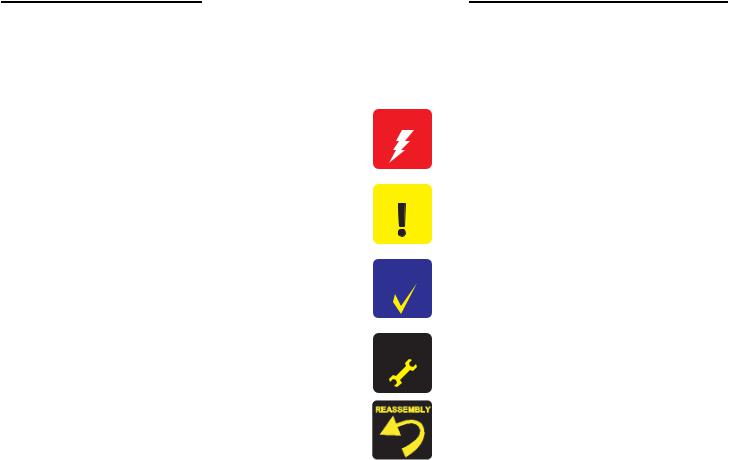
Dimension
With the output tray and paper support closed Width: 435 mm (17.1 inches)
Depth: 219 mm (8.6 inches) Height: 165 mm (6.5 inches)
Maximum dimension
Width: 435 mm (17.1 inches) Depth: 418 mm (16.5 inches) Height: 289 mm (11.4 inches)
Weight
2.8 kg (6.2 lb) without ink cartridges
Figure 1-1. External View
PRODUCT DESCRIPTION |
Features |
10 |
Epson Stylus C58/C59/ME 2/C79/D78/C90/C91/C92/D92/T20/T20E/T23/T26/S20/T10/T11/ME 30/T21/T24/T27/S21 |
Revision E |
1.2 Printer Specifications
Item
Print method
Nozzle configuration
Print direction
Print resolution
Control code
Internal font
Input buffer size Paper feed method Paper path
Paper feed rates (TBD)
Table 1-2. Printer Specifications
Specification
On-demand ink jet
Black: 90 nozzles
Color: 87 nozzles (29 each cartridge: cyan, magenta, yellow) Bidirectional with logic seeking
Horizontal x Vertical (dpi)
• 360 x 120 |
• 720 x 720 |
• 360 x 360 |
• 1440 x 720 |
• 360 x 720 |
• 5760 x 1440 |
•ESC/P2 expanded raster graphics code
•EPSON Remote command
Character code: ASCII 20H to 7FH Font: Bit map LQ font
EPSON Courier
32 Kbytes
Friction feed with ASF (Auto Sheet Feeder) Sheet feeder, top entry
• High quality mode, 10.16-mm (0.4") feed TBD mm/sec (TBD inch/sec)
• High speed mode, continuous feed
TBD mm/sec (TBD inch/sec)
PRINT SPEED & PRINTABLE WIDTH
Table 1-3. Character Mode
Character Pitch |
Printable Columns |
CR Speed |
10 CPI (Pica) |
80 |
419 mm/s (165 CPS*) |
Note * : CPS: Characters per second
Horizontal Printable
Resolution Area
360 dpi |
209.8 mm |
|
(8.26") |
||
|
720 dpi |
209.8 mm |
|
(8.26") |
||
|
||
1440 dpi |
209.8 mm |
|
(8.26") |
||
|
||
5760 dpi |
209.8 mm |
|
(8.26") |
||
|
Table 1-4. Graphics Mode
|
Dot Size |
||
|
|
Epson Stylus C79/ |
|
Max. Dot |
|
D78/C90/C91/C92/ |
|
Epson Stylus C58/ |
D92/T20/T20E/ |
||
Count |
C59/ME 2 |
T23/T26/S20/T10/ |
|
|
|||
|
|
T11/ME 30/T21/ |
|
|
|
T24/T27/S21 |
|
|
Eco |
Eco |
|
2976 |
VSD1 |
VSD1 |
|
|
|||
|
--- |
VSD2’ (Color) |
|
|
VSD2 |
VSD2 |
|
5952 |
--- |
VSD2’ (Black) |
|
VSD3 |
--- |
||
|
|||
|
--- |
VSD3’ (Color) |
|
11904 |
VSD3 |
VSD3 |
|
--- |
VSD3’ (Black) |
||
|
|||
23808 |
VSD3 |
VSD3 |
|
CR
Speed
723.9mm/s (360 CP)S
419.1mm/x (165 CPS)
609.6mm/s (240 CPS)
PRODUCT DESCRIPTION |
Printer Specifications |
11 |

Epson Stylus C58/C59/ME 2/C79/D78/C90/C91/C92/D92/T20/T20E/T23/T26/S20/T10/T11/ME 30/T21/T24/T27/S21 |
Revision E |
1.2.1 Paper Support
Following table shows the paper type and sizes supported by the printer. Supported paper type and sizes vary depending on the markets.
Table 1-5. Paper Support
Item
Plain paper
Recycled paper
Envelope
(Bond paper, Air mail, PPC)
|
Premium Ink Jet Plain Paper |
|
Premium Bright White Paper |
|
Bright White Ink Jet Paper |
paper |
Premium Photo Paper Glossy (EAI) |
specialEPSON |
Premium Glossy Photo Paper (Other) |
|
|
|
Premium Photo Paper Semi-Gloss (EAI) |
|
Premium Semigloss Photo Paper (Other) |
|
Premium Presentation Paper Matte (EAI) |
|
Matte Paper-Heavyweight (Other) |
Paper Size
Letter
Legal
Half Letter
A4
A5
A6
B5 User defined
No.10
DL
C6
A4
A4*7
Letter*5
A4
Letter*3
A4*1 8" x 10"*3 5" x 7"*1 4" x 6"*1 16:9 wide*1 L (3R)*1*4
Letter*3
A4*1 4" x 6"*1 Letter*3 A4*1
8" x 10"*2*6
Thickness Weight
(mm)
0.08-0.11 |
64-90 g/m2 |
|
(17-24 lb.) |
||
|
N/A |
45-75g/m2 |
|
(12-20 lb.) |
||
|
0.1180 g/m2 (21 lb.)
0.1190 g/m2 (24 lb.)
0.1392.5 g/m2 (25 lb.)
0.27255 g/m2 (68 lb.)
0.27250 g/m2 (66 lb.)
0.23 167 g/m2 (45 lb.)
Table 1-5. Paper Support
|
Item |
Paper Size |
Thickness |
Weight |
|
|
(mm) |
||||
|
|
|
|
||
|
Presentation Paper Matte (EAI) |
A4*2 |
0.12 |
102 g/m2 (27 lb.) |
|
|
Photo Quality Inkjet Paper (Other) |
||||
|
|
|
|
||
|
|
Letter*3 |
|
|
|
|
Photo Paper Glossy (EAI) |
A4*1 |
0.25 |
258 g/m2 (68 lb.) |
|
|
Glossy Photo Paper (EUR, Asia) |
5" x 7"*1 |
|||
paper |
|
|
|||
|
4" x 6"*1 |
|
|
||
|
|
|
|
||
special |
|
Letter*3 |
|
|
|
|
A4*3 |
|
|
||
|
|
|
|
||
EPSON |
Ultra Premium Photo Paper Glossy (EAI) |
8" x 10"*3 |
0.30 |
290 g/m2 (77 lb.) |
|
Ultra Glossy Photo Paper (Other) |
5" x 7"*1 |
||||
|
|||||
|
|
|
|||
|
|
4" x 6"*1 |
|
|
|
|
|
L (3R)*1*4 |
|
|
|
|
|
A4*6 |
|
|
|
|
Photo Paper (Others) |
5" x 7"*6 |
0.24 |
190 g/m2 (51 lb.) |
|
|
|
4" x 6"*6 |
|
|
Note 1: For paper width and length, see Table 1-6, “Paper Width and Length,” on page 13. Note *1: Borderless printing supported.
*2: Supported only by Epson Stylus T20/T20E/T23/T26/S20/T10/T11/ME30.
*3: Borderless printing is supported only by Epson Stylus T20/T20E/T23/T26/S20/T10/ T11/ME30/T21/T24/T27/S21.
*4: Not supported by Epson Stylus T20/T20E/T23/T26/S20/T10/T11/ME30/T21/T24/ T27/S21.
*5: Supported only by Epson Stylus T21/T24/T27/S21.
*6: Borderless printing supported only for Epson Stylus T21/T24/T27/S21. *7: Supported only by Epson Stylus T20/T20E/T23/T26/S20/T10/T11/ME30.
CAUTION Make sure that the paper is not wrinkled, fluffed, torn, or folded.
The curve of paper must be 5 mm or below.
When printing onto an envelope, be sure that the flap is on the long edge and is folded.
Do not use the adhesive envelopes.
Do not use double envelopes and cellophane window envelopes.
PRODUCT DESCRIPTION |
Printer Specifications |
12 |
Epson Stylus C58/C59/ME 2/C79/D78/C90/C91/C92/D92/T20/T20E/T23/T26/S20/T10/T11/ME 30/T21/T24/T27/S21 |
Revision E |
PAPER WIDTH AND LENGTH
Table 1-6. Paper Width and Length
|
Paper Size |
Width |
Length |
|
|
A4 |
210 mm (8.3") |
297 mm (11.7") |
|
|
A5 |
148 mm (5.8") |
210 mm (8.3") |
|
|
A6 |
148 mm (5.8") |
210 mm (8.3") |
|
|
B5 |
182 mm (7.2") |
257 mm (10.1") |
|
|
Letter |
215.9 mm (8.5") |
279.4 mm (11") |
|
sheet |
Legal |
215.9 mm (8.5") |
355.6 mm (14") |
|
Half Letter |
139.7 mm (5.5") |
215.9 mm (8.5") |
||
Cut |
||||
8" x 10" |
203.2 mm |
254 mm |
||
|
||||
|
5" x 7" |
127 mm |
178 mm |
|
|
4" x 7.11" |
101.6 mm |
180.6 mm |
|
|
4" x 6" |
101.6 mm |
152.4 mm |
|
|
L (3R) |
89 mm (3.5") |
127 mm (5") |
|
|
User defined |
50.8-329 mm |
127-1117.6 mm |
|
|
(2-12.6") |
(5-44") |
||
|
|
|||
Envelope |
No.10 |
104.8 mm (4.125") |
241.3 mm (9.5") |
|
DL |
110 mm |
220 mm |
||
|
||||
|
C6 |
114 mm |
162 mm |
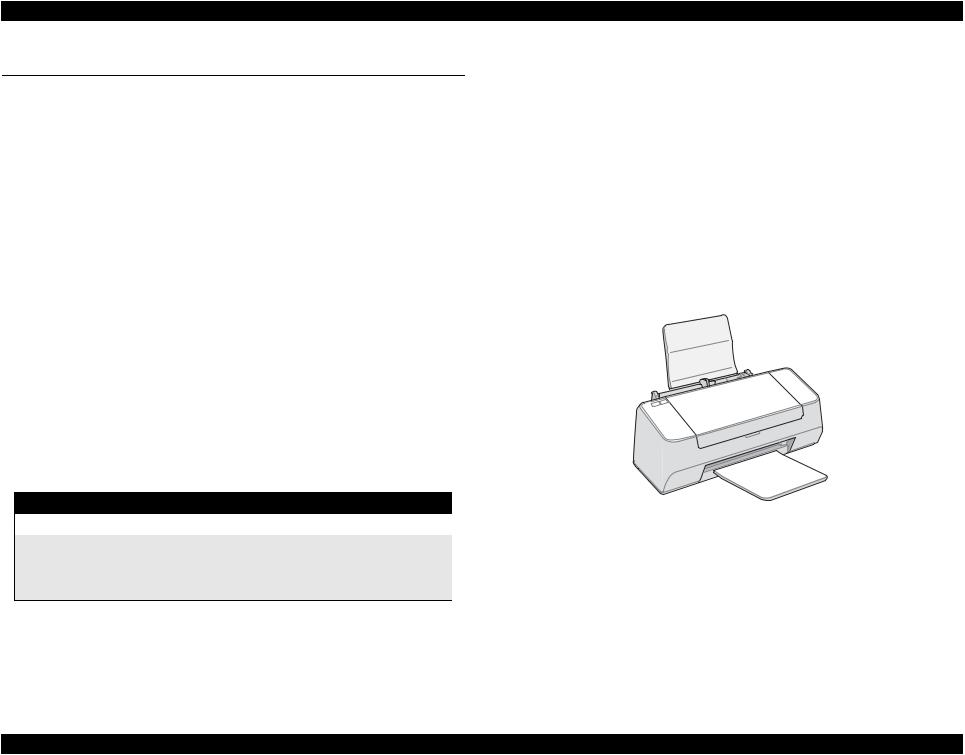
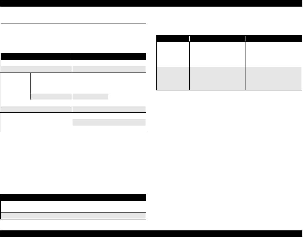
1.2.2 Printable Area Size and Margins
Refer to the table and figure below for the printable area size and margins.
Table 1-7. Guaranteed Print Area
|
|
A |
B-L |
B-R |
C |
D |
C58/C59/ME 2/C79/D78/ |
|
|
|
|
|
|
C90/C91/C92/D92/T20/ |
Any size/ |
3 mm |
3 mm |
3 mm |
12.5 mm |
20 mm |
T20E/T23/T26/S20/T10/ |
Envelope |
(0.12") |
(0.12") |
(0.12") |
(4.92") |
(7.87") |
T11/ME 30 |
|
|
|
|
|
|
|
Any size |
3 mm |
3 mm |
3 mm |
3 mm |
- |
|
(0.12") |
(0.12") |
(0.12") |
(0.12") |
||
T21/T24/T27/S21 |
|
|
||||
|
3 mm |
5 mm |
5 mm |
|
20 mm |
|
|
Envelope |
- |
||||
|
(0.12") |
(0.2") |
(0.2") |
(7.87") |
||
|
|
|
Note : This is minimum margin. |
|
|
A |
|
|
B-L |
B-R |
|
Cut sheet |
C |
Borderless printing* |
|
||
A |
B-R |
D |
|
|
|
|
B-L |
Envelope |
|
|
Note * : Borderless printing is carried out by enlarging the image size wider than the paper size as shown in the figure. The image width protruding from the paper size is shown below.
Paper Size
A4, Letter, 8" x 10", 5" x 7", 4" x 7.11"
4" x 6", L (3R)
Table 1-8. Borderless Printing
Top |
Bottom |
Left/Right |
2.96 mm (0.12") |
4.02 mm (0.16") |
2.54 mm (0.1") |
2.82 mm (0.11") |
3.60 mm (0.14") |
2.54 mm (0.1") |
PRODUCT DESCRIPTION |
Printer Specifications |
13 |

Epson Stylus C58/C59/ME 2/C79/D78/C90/C91/C92/D92/T20/T20E/T23/T26/S20/T10/T11/ME 30/T21/T24/T27/S21 |
Revision E |
1.2.3 Ink Cartridge
Type/color: EPSON-brand special ink cartridges
Table 1-9. Epson Stylus C58/C59/ME 2
Color |
ECC |
Pacific, Asia (Other) |
Black |
T0761 |
T0751 |
Cyan |
T0762 |
T0752 |
Magenta |
T0763 |
T0753 |
Yellow |
T0764 |
T0754 |
Table 1-10. Epson Stylus C79/D78
Color |
Latin, Asia, Pacific |
Europe |
Black |
T0731 |
T0711 |
Cyan |
T0732 |
T0712 |
Magenta |
T0733 |
T0713 |
Yellow |
T0734 |
T0714 |
Table 1-11. Epson Stylus C90/C91/C92/D92
Color |
Latin |
Asia |
Europe |
CISMEA |
|
Black |
T0731 |
T0731 |
T0711 |
T0921 |
|
T0901 |
T0911* |
||||
|
|
|
|||
Cyan |
T0732 |
T0732 |
T0712 |
T0922 |
|
T0912* |
|||||
|
|
|
|
||
Magenta |
T0733 |
T0733 |
T0713 |
T0923 |
|
T0913* |
|||||
|
|
|
|
||
Yellow |
T0734 |
T0734 |
T0714 |
T0924 |
|
T0914* |
|||||
|
|
|
|
Note * : Except EHK.
Table 1-12. Epson Stylus T20/T20E/T23/T26/S20/T21/T24/T27/S21
Color |
Latin 1 |
Latin 2 |
CISMEA |
Euro |
Asia |
|
Black |
T0731N |
T1161 |
T0921N |
T0711 |
T0731N |
|
T0901N |
T1171 |
T0891 |
T0911N |
|||
|
|
|||||
Cyan |
T0732N |
|
T0922N |
T0712 |
T0732N |
|
|
T0892 |
T0912N |
||||
|
|
|
|
|||
Magenta |
T0733N |
|
T0923N |
T0713 |
T0733N |
|
|
T0893 |
T0913N |
||||
|
|
|
|
|||
Yellow |
T0734N |
|
T0924N |
T0714 |
T0734N |
|
|
T0894 |
T0914N |
||||
|
|
|
|
|
Table 1-13. Epson Stylus T10/T11 |
Color |
ESP/EKL |
Black |
T0731N, T0911N |
Cyan |
T0732N, T0912N |
Magenta |
T0733N, T0913N |
Yellow |
T0734N, T0914N |
|
Table 1-14. Epson ME 30 |
Color |
ECC |
Black |
T1091 |
Cyan |
T1092 |
Magenta |
T1093 |
Yellow |
T1094 |
PRODUCT DESCRIPTION |
Printer Specifications |
14 |
Epson Stylus C58/C59/ME 2/C79/D78/C90/C91/C92/D92/T20/T20E/T23/T26/S20/T10/T11/ME 30/T21/T24/T27/S21 |
Revision E |
|
Shelf life: Two years from production date (if unopened), six months after |
|
opening package. |
|
Storage Temperature |
|
Table 1-15. Storage Temperature |
Situation
When stored in individual boxes
When installed in main unit
Storage Temperature
-30 oC to 40 oC (-22oF to 104oF)
-20 oC to 40 oC (-4oF to 104oF)
Limit
1 month max. at 40 oC (104oF)
Dimension
Epson Stylus C58/C59/ME 2
12.7mm (W) x 43 mm (D) x 47 mm (H)
Epson Stylus C79/D78/C90/C91/C92/D92/T20/T20E/T23/T26/S20/T10/T11/ ME30/T21/T24/T27/S21
12.7mm (W) x 68 mm (D) x 47 mm (H)
CAUTION The ink cartridge cannot be refilled.
The ink cartridge that passes the expiration date should not be used.
The ink in the ink cartridge freezes at -16 °C (3.2 oF). Ink thaws
and is usable after approximately three hours at 25 °C (77oF).
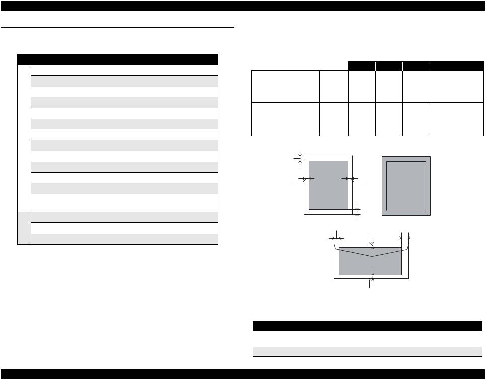
1.2.4 Black Ink Save Mode
Black ink save mode allows you to print images with color ink only when the remaining amount of black ink is low. This mode can be selected when the remaining amount of color ink is sufficient since black areas of the images are printed with a mixture of other colors.
Supported OS: Windows 98, ME, 2000, XP, XP x64, Vista Macintosh OS X 10.3.9, 10.4.x, 10.5.x
NOTE: Windows Vista and Macintosh OS are for Epson Stylus T21/T24/ T27/S21 only.
Printing mode: Plain Paper & Text Mode (360 dpi)
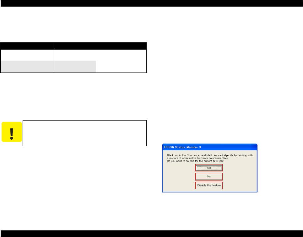
Operating procedure
1.User carries out printing from an application.
2.The printer driver checks both the printing mode and the amount of remaining ink, and displays the specific window if the conditions described below are all met.
•Selected printing mode supports black ink save mode.
•Remaining amount of black ink is less than 5%, or the status of the black ink is “ink low”.
•Remaining amount of all the color ink is more than 10%, or the status of all the color ink is NOT “ink low”.
 Starts printing in black ink
save mode.
 Starts printing in a normal
manner.
 Starts printing in a normal
  manner. This window will not be displayed again until the black ink cartridge is replaced.
Flowchart 1-1. Black Ink Save Mode
PRODUCT DESCRIPTION |
Printer Specifications |
15 |

Epson Stylus C58/C59/ME 2/C79/D78/C90/C91/C92/D92/T20/T20E/T23/T26/S20/T10/T11/ME 30/T21/T24/T27/S21 |
Revision E |
1.3 Interface
Epson Stylus C58/C59/ME 2 and Epson Stylus C79/D78/C90/C91/C92/D92/T20/ T20E/T23/T26/S20/T10/T11/Epson ME 30/T21/T24/T27/S21 provide an USB interface.
1.3.1 USB Interface
Standard: |
Based on Universal Serial Bus Specifications Revision 1.1, |
|
|
Universal Serial Bus Device Class Definition for Printing |
|
|
Devices Version 1.1 |
|
Descriptors: |
Based on Design Specification for USB Device Requests and |
|
|
USB Descriptors for EPSON USB Printer |
|
Product ID: |
0005h |
|
Transfer rate: |
12 Mbps (Full Speed Device) |
|
Cable length: |
Under 2 meters (6.6 feet) |
|
Device ID |
|
|
|
Table 1-16. Device ID |
|
When IEEE 1284.4 is Enabled |
When IEEE 1284.4 is Disabled |
|
@EJL[SP]ID[CR][LF] |
|
@EJL[SP]ID[CR][LF] |
MFG:EPSON; |
|
MFG:EPSON; |
CMD:ESCPL2,BDC,D4,D4PX; |
CMD:ESCPL2,BDC; |
|
MDL:Model Name; |
|
MDL:Model Name; |
CLS:PRINTER; |
|
CLS:PRINTER; |
DES:EPSON[SP] Model Name; |
DES:EPSON[SP] Model Name |
|
[FF] |
|
[FF] |
NOTE: “Model Name” represents each model name. (TBD)
PRODUCT DESCRIPTION |
Interface |
16 |
Epson Stylus C58/C59/ME 2/C79/D78/C90/C91/C92/D92/T20/T20E/T23/T26/S20/T10/T11/ME 30/T21/T24/T27/S21 |
Revision E |
1.4 General Specifications
1.4.1 Electrical Specifications
Primary power input
Table 1-17. Primary power input
100-120 V model |
220-240 V model |
Rated power supply voltage (ACV) Input voltage range (ACV)
C58/C59/ME 2/C79/
D78/C90/C91/C92/D92/
Rated current (A) T20/T20E/T23/T26/S20/ T10/T11/ME 30
T21/T24/T27/S21
Rated frequency (Hz) Input frequency range (Hz)
100 to 120 |
220 to 240 |
90 to 132 |
198 to 264 |
0.4 (max. 0.7)
0.2 (max. 0.4)
0.4 (max. 0.8)
50 to 60
49.5 to 60.5
11 (ISO10561 Letter Pattern)
Power consumption (W) |
2.5 (Sleep mode) |
3.0 (Sleep mode) |
|
0.2 (Power off mode) |
0.4 (Power off mode) |
Note 1: This product complies with the “Energy Star” standards.
2:If the printer is not operated for more than five minutes, the standby function reduces the current to the motor to conserve power.
Dielectric strength
AC1000 Vrms for 1 min. or AC1200 Vrms for 1 sec. (100-120V version)
AC1500 Vrms for one min. (220-240V version)
1.4.3 Safety Approvals
Safety standards
EMI
Table 1-19. Safety Approvals
100-120 V version
UL60950
CSA C22.2 No.60950
NOM-019-SCFI-1998*
CNS14336 (IEC60950)* FCC part15 subpart B class B CSA C108.8 Class B
CNS13438 Class B*
220-240 V version
EN 60950
GOST-R (IEC60950, CISPR22)* K60950-1*
IEC60950-1*
EN 55022(CISPR Pub.22) class B AS/NZS CISPR22 class B
KN22 Class B* KN61000-4-2/-3/-4/-5/-6/-11*
Note * : Only Epson Stylus T21/T24/T27/S21
1.4.4 CE Marking
220-240V version
Low voltage directive 73/23/EEC: EN60950
EMC directive 89/336/EEC: |
EN5502 Class B, EN61000-3-2, |
|
EN61000-3-3, EN55024 |
1.4.2 Acoustic Noise
Table 1-18. Acoustic Noise
Model |
Noise level* |
|
Epson Stylus C58/C59/ME 2/C79/D78/C90/C91/C92/D92/ |
Approx. 44 dB |
|
T20/T20E/T23/T26/S20/T10/T11/ME 30 |
||
|
||
Epson Stylus T21/T24/T27/S21 |
Approx. 47 dB |
|
Note * : According to ISO7779 |
|
PRODUCT DESCRIPTION |
General Specifications |
17 |
 Epson Stylus C58/C59/ME 2/C79/D78/C90/C91/C92/D92/T20/T20E/T23/T26/S20/T10/T11/ME 30/T21/T24/T27/S21 Revision E
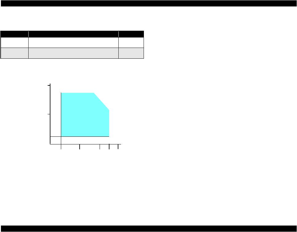
1.4.5 Environmental Performance
Table 1-20. Environmental Performance
Condition |
Temperature |
Humidity*2 |
Impact |
Vibration |
|||
Operating |
10 to 35°C |
20 to 80%*4 |
1G, |
0.15G |
|||
(50 to 95°F)*3*4 |
1 x 10⁻³ seconds |
||||||
|
|
|
|
|
|||
Not operating*1 |
-20 to 40°C |
5 to 85% |
2G, |
0.50G |
|||
(-4°F to 140°F) |
2 x 10⁻³ seconds |
||||||
|
|
|
|
|
|||
Note *1 |
: |
After opening package |
|
|
|
||
*2 |
: |
No condensation |
|
|
|
||
*3 |
: One month at 40°C (104°F) |
|
|
|
|||
*4 |
: Under the following conditions: |
|
|
|
|||
|
|
|
90 |
|
|
|
|
80 
70 
60 
Humidity (%) 50
40 
30 
20 

|
|
27/80 |
|
|
10/50 |
20/68 |
30/86 |
35/95 |
40/104 |
Temperature (°C/°F)
1.4.6 Durability
Total print life:10,000 pages (A4, Letter) or three years (whichever comes first)
Printhead life: Seven billion shots (per nozzle) or five years (whichever comes first)
PRODUCT DESCRIPTION |
General Specifications |
18 |
Epson Stylus C58/C59/ME 2/C79/D78/C90/C91/C92/D92/T20/T20E/T23/T26/S20/T10/T11/ME 30/T21/T24/T27/S21 |
Revision E |
1.5 Control Panel
1.5.1 Buttons
The control panel contains following two buttons (non-lock type), which are used to set and execute some operations. The functions of each button are described in the table below.
|
Table 1-21. Operations |
|
Button |
Function |
|
Power |
Turns on or off this unit. |
|
|
When Paper out occurred |
|
|
Loads paper. |
|
|
When Paper jam occurred |
|
|
Ejects paper. |
|
|
When Double feed occurred |
|
|
Clears the error and resumes the printing. |
|
|
When Ink end or No ink cartridge occurred |
|
Maintenance |
Moves the carriage to ink-check position. |
|
When the carriage is in the ink-check position |
||
|
||
|
Moves the carriage slightly to check the adjacent ink cartridge. |
|
|
When the carriage is in “Ink low” or “Ink out” position |
|
|
Moves the carriage to the replacement position. |
|
|
During printing |
|
|
Cancels the current print job. |
|
|
When pressed for three seconds |
|
|
Cleans the printhead. |
|
|
When the printer is turning on |
|
Power + Maintenance* |
Print a nozzle check pattern. |
|
When the printer is on |
||
|
||
|
Shuts down the printer. |
Note * : Hold down [Maintenance] first and press [Power]. Keep the buttons pressed for over seven seconds.
1.5.2 Indicators
The control panel contains following two LED to indicate some status.
|
|
Table 1-22. |
Indicators |
||
LED |
|
|
Function |
||
Power [Green] |
Lights while the printer is turned on. |
||||
|
Lights: Paper out, Paper jam, Double feed, No ink cartridge, |
||||
Maintenance [Red] |
|
Ink end, Incorrect ink cartridge |
|||
|
Flashes: Ink low |
|
|
|
|
Power Button |
Maintenance Button |
||||
|
|
|
|
|
|
|
|
|
|
|
|
|
|
|
|
|
|
Power LED
LED
Maintenance LED
Figure 1-2. Control Panel
PRODUCT DESCRIPTION |
Control Panel |
19 |
Epson Stylus C58/C59/ME 2/C79/D78/C90/C91/C92/D92/T20/T20E/T23/T26/S20/T10/T11/ME 30/T21/T24/T27/S21 |
Revision E |
1.5.3 Errors and Panel Status
Followings are the errors that occur on the printer:
Fatal error: |
Carriage control error. |
Maintenance request: |
Waste ink pads need to be replaced. |
Ink end: |
Ink has run out. |
No ink cartridge: |
Ink cartridge(s) is not installed. |
Incorrect ink cartridge: |
Non-genuine ink cartridge(s) is installed. |
Paper jam: |
Paper remains in the paper path. |
Paper out: |
Failed to load papers. |
Double feed: |
Two or more papers have been fed during duplex printing. |
Ink low (warning): |
Ink is running low. |
Table 1-23. Errors and Panel Status
Printer Status |
Indicators |
Priority |
||
Power LED |
Maintenance LED |
|||
|
|
|||
Turning the power off |
Flashes fast |
Off |
1 |
|
Fatal error |
Off |
Flashes fast |
2 |
|
Maintenance request |
Flashes alternately |
3 |
||
Paper jam |
--- |
On |
4 |
|
Paper out |
--- |
On |
4 |
|
Double feed |
--- |
On |
4 |
|
Ink cartridge replacement |
Flashes |
--- |
5 |
|
Ink sequence |
Flashes |
--- |
6 |
|
Incorrect ink cartridge |
--- |
On |
7 |
|
No ink cartridge/Ink end |
--- |
On |
7 |
|
Data processing |
Flashes |
--- |
8 |
|
Ink low |
--- |
Flashes |
9 |
|
Turning the power on |
On |
--- |
10 |
|
Note 1: “---”: no change |
|
|
|
|
2: When multiple errors occur at the same time, the one with higher priority will be indicated.
1.5.4 Printer Initialization
There are four kinds of initialization method, and the following explains each initialization.
1.Power-on initialization
This printer is initialized when turning the printer power on, or printer recognized the cold-reset command (remote RS command).
When printer is initialized, the following actions are performed.
(a)Initializes printer mechanism
(b)Clears input data buffer
(c)Clears print buffer
(d)Sets default values
2.Operator initialization
This printer is initialized when turning the printer power on again within 10 seconds from last power off, or printer recognized the -INIT signal (negative pulse) of parallel interface.
When printer is initialized, the following actions are performed.
(a)Cap the printer head
(b)Eject a paper
(c)Clears input data buffer
(d)Clears print buffer
(e)Sets default values
3.Software initialization
The ESC@ command also initialize the printer.
When printer is initialized, the following actions are performed.
(a)Clears print buffer
(b)Sets default values
4.Power-on initialization except I/F
The printer recognized the IEEE 1284.4 “rs” command.
When printer is initialized, the following action is performed.
(a)Initializes printer mechanism
(b)Clears input data buffer
(c)Clears print buffer
(d)Sets default values except I/F
PRODUCT DESCRIPTION |
Control Panel |
20 |
C H A P T E R
2
OPERATING PRINCIPLES
Epson Stylus C58/C59/ME 2/C79/D78/C90/C91/C92/D92/T20/T20E/T23/T26/S20/T10/T11/ME 30/T21/T24/T27/S21 |
Revision E |
2.1 Overview
This section describes the operating principles of the printer mechanism and electrical circuit boards. The printer mechanism does not differ between the Epson Stylus C58/ C59/ME2 and Epson Stylus C79/D78/C90/C91/C92/D92/T20/T20E/T23/T26/S20/ T10/T11/Me 30/T21/T24/T27/S21.
2.2 Printer Mechanism
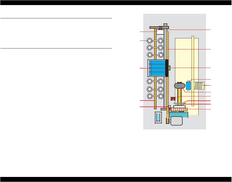
Printer mechanism of Epson Stylus C58/C59/ME 2 and Epson Stylus C79/D78/C90/ C91/C92/D92/T20/T20E/T23/T26/S20/T10/T11/ME 30/T21/T24/T27/S21 consists of printhead, carriage mechanism, paper loading/feeding mechanism, and ink system. As in the case of conventional models, Epson Stylus C58/C59/ME 2 and Epson Stylus C79/D78/C90/C91/C92/D92/T20/T20E/T23/T26/S20/T10/T11/ME 30/T21/T24/T27/ S21 has two motors; one is a stepping motor for paper loading/feeding mechanism, and the other is a DC motor for carriage mechanism.
Papers are fed from the backside and ejected from the front side of the printer. Paper feeding mechanism feeds papers using the LD roller and the retard roller.
PF motor |
PF roller |
|
|
||
Star wheel |
|
|
rollers |
|
|
|
CR timing belt |
|
Carriage unit |
CR encoder |
|
sensor |
||
|
||
|
Retard roller |
|
|
Compression |
|
|
spring |
|
|
LD roller |
|
Paper eject |
PE sensor |
|
Cam, large |
||
roller |
||
CR lock lever |
Cam, small |
|
Clutch |
||
|


 Pump unit Cap unit


 CR motor
Figure 2-1. Printer Mechanism Outline
OPERATING PRINCIPLES |
Overview |
22 |
Epson Stylus C58/C59/ME 2/C79/D78/C90/C91/C92/D92/T20/T20E/T23/T26/S20/T10/T11/ME 30/T21/T24/T27/S21 |
Revision E |
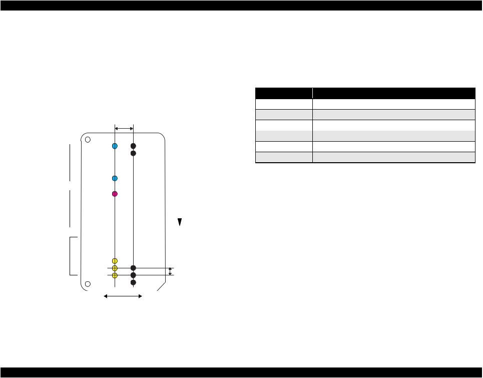
2.2.1 Printhead Specifications
The Printhead of this product is a D2-CHIPS type.
Nozzle configuration
Monochrome 90 nozzles
Color 29 nozzles x 3 (Cyan, Magenta, Yellow)
The following shows the arrangement of the nozzles and the color arrangement of each nozzle line when viewed the printhead from behind.
2.822mm (40/360 inch)
|
C#29 |
K#90 |
|
|
|
|
K#89 |
|
|
Cyan: 29nozzles |
|
|
|
|
|
C#1 |
|
|
|
|
M#29 |
|
|
|
|
Color |
Black |
Paper Loading |
|
Magenta: 29nozzles |
Direction |
|||
|
|
M#1 
Y#29
Yellow: 29nozzles
Y#3
Y#2 |
K#3 |
0.2117mm |
|
Y#1 |
K#2 |
||
(1/120 inch) |
|||
|
K#1 |
|
Carriage Moving Direction
Figure 2-2. Nozzle Rear View
2.2.2 Carriage Mechanism
Main components of the carriage mechanism are carriage unit (including printhead, CR encoder sensor), CR motor, timing belt, and CR scale.
2.2.2.1 CR Motor Specifications
|
Table 2-1. CR Motor Specifications |
Item |
Specification |
Type |
Motor with DC brush |
Drive voltage |
+42 V ± 5% (applied voltage to the driver) |
Electric resistance |
28.8 Ω ± 10% |
Inductance |
20.1 mH ± 25% |
Drive method |
PWM, constant-current chopping |
Drive IC |
A6628 |
OPERATING PRINCIPLES |
Printer Mechanism |
23 |
Epson Stylus C58/C59/ME 2/C79/D78/C90/C91/C92/D92/T20/T20E/T23/T26/S20/T10/T11/ME 30/T21/T24/T27/S21 |
Revision E |
2.2.3 Paper Feeding Mechanism
Paper loading/feeding mechanism consist of CR lock lever inside the ink system, LD roller shaft (including clutch mechanism), and ASF unit.
CR lock lever and clutch mechanism play an important role in paper loading mechanism. Refer to 2.2.3.2 Drive Process (p24) for details.
2.2.3.1 PF Motor Specifications (For both ASF and Pump motor)
Table 2-2. PF Motor Specification
Item |
Specification |
Type Drive voltage
Wire wound resistance
Inductance
Drive method
Drive IC
4-phase, 48-pole PM stepping motor
+42 V ± 5% (applied voltage to the driver)
4.3 Ω +8 / -12% (per one phase at 20 °C)
5.5 mH ± 20% (1KH, 1Vrms)
Bipolar drive
2-2 phase, 1-2 phase, W1-2phase, 2W1-2phase, 4W1-2 phase constant-current drive
A6628
2.2.3.2 Drive Process
1.Drive of the PF motor is always transmitted to the paper eject roller and the PF roller, however, it is not transmitted to the LD roller and the retard roller owing to the clutch of the LD roller shaft.
2.The carriage unit moves to the ASF trigger position once the paper loading command is received.
3.PF motor is rotated counter clockwise, and the clutch is released by the CR lock lever.
4.After the clutch is released, the PF motor rotates clockwise. Drive is transmitted to the LD roller and the paper loading operation begins.
5.During paper loading operation, papers are fed from the ASF unit to inside the printer by the rotating movement of the two cams of the LD roller.
Cam, large:releases hopper
Cam, small:releases paper back lever
6.Once a sheet of paper is fed, the hopper and the paper back lever bring back rest of the papers to the position in readiness by the rotating movement of the two cams mentioned above.
7.When the LD roller is turned a full circle, the CR lock lever release the clutch and the drive to the LD roller is interfered.
OPERATING PRINCIPLES |
Printer Mechanism |
24 |

Epson Stylus C58/C59/ME 2/C79/D78/C90/C91/C92/D92/T20/T20E/T23/T26/S20/T10/T11/ME 30/T21/T24/T27/S21 |
Revision E |
2.2.4 Ink System Mechanism
The Ink system mechanism consists of pump mechanism and capping mechanism that includes wiper mechanism.
2.2.4.1 Pump Unit Mechanism
When the PF motor turns, power is always transmitted to the ink system.
Table 2-3. PF Motor Rotational Direction & Ink System Mechanism
Direction* |
Function |
Counterclockwise |
Absorbs the ink by the Pump Unit |
Clockwise |
Release pump. |
Note * : The PF Motor rotational direction = seen from the left side of the printer.
2.2.4.2 Capping Mechanism
The Capping mechanism covers the printhead with the cap to prevent the nozzle from increasing viscosity when the printer is in stand-by state or when the printer is off.
OPERATING PRINCIPLES |
Printer Mechanism |
25 |
Epson Stylus C58/C59/ME 2/C79/D78/C90/C91/C92/D92/T20/T20E/T23/T26/S20/T10/T11/ME 30/T21/T24/T27/S21 |
Revision E |
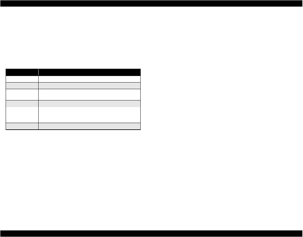
2.3 Power-On Sequence
This section describes the power-on sequences.
Condition: Normal power-on sequence
Completing ink charge.
No paper on the paper path.
The Printhead is capped with the Cap of the Ink System.
The Carriage is locked by the CR Lock.
Table 2-4. Normal power-on sequence
Operation*1
1.Checking waste ink overflow
2.Seeking the home position
2-1.The carriage moves to the 80-digit side slowly and confirms it touches the CR lock.
2-2.The carriage moves to the 0-digit side slowly to leave from the CR lock.
2-3.Checks if paper does not exist with the PE sensor and the PF Motor rotates clockwise for two seconds to release the CR lock.
2-4.The carriage moves to the 80-digit side slowly and confirms that the CR lock is released.
2-5.The carriage quickly moves to the 80-digit side by the Left Frame.
2-6.After the carriage continuously moves to the 80-digit side slowly and confirms it touches the Left Frame, sets the distance from the home position to the Left Frame as the theoretical value.
2-7.The carriage quickly moves to the 0-digit side and slows down as it gets to its home position, and stops there.
3.Low temperature operation sequence*3
3-1.The carriage moves back and forth between its home position and the 80-digit side for two times.
Carriage/PF roller movement and position*2
 lock
lock
 lock is released
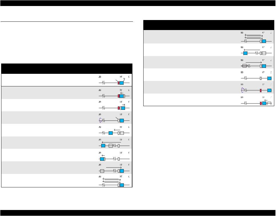
Table 2-4. Normal power-on sequence
Operation*1
4.CR measurement
4-1.The carriage moves back and forth between its home position and the 80-digit side for two times.
5.Detecting ink cartridge and initializing ink system* 4
5-1.The carriage moves to the 80-digit side for IES detection. 5-2.The carriage returns to its home position.
Carriage/PF roller movement and position*2
5-3.The carriage slowly moves to the CR lock set position.
5-4.The PF motor rotates counterclockwise and sets the CR lock.
5-5.The carriage slowly returns to its home position.
Note *1: The rotation direction of the PF Motor is as follows.
Clockwise direction |
: Paper is fed normally |
Counterclockwise direction |
: Paper is fed backward |
*2: The conditions of the CR lock are as follows. Red: CR lock is set
White: CR lock is released
*3: Executed when the detected temperature is under 5 oC (41oF) by the thermistor on the Printhead.
*4: The empty sanction operation may occur depending on the situation.
OPERATING PRINCIPLES |
Power-On Sequence |
26 |

C H A P T E R
3
TROUBLESHOOTING

Epson Stylus C58/C59/ME 2/C79/D78/C90/C91/C92/D92/T20/T20E/T23/T26/S20/T10/T11/ME 30/T21/T24/T27/S21 |
Revision E |
3.1 Overview
This chapter describes how to solve problems.
WARNING
Be careful to avoid electric shocks when checking the electrical circuit boards (C664 MAIN, PSE and B circuit boards) while the power is turned on.
Touching an FET, transistor or heat sink with one hand while touching a metal part of the mechanism with the other hand could result in an electric shock, so carefully avoid this.
After initial filling of ink has been repeated several times,
|
immediate moving or tilting of the printer could result in |
|
leaking of ink that has not been completely absorbed by the |
|
Waste Ink Pad. When initial filling of ink has been repeated |
|
several times, check the ink remaining in the tip of the Waste |
|
Ink Tube and the waste ink not absorbed by the Waste Ink |
|
Pad before moving the printer. |
CHECK |
Disassembly and reassembly of parts is often required when |
POINT |
identifying the causes of problems. The parts should be |
|
disassembled and re-assembled correctly while referring to |
|
DISASSEMBLY/ASSEMBLY (p31) so that the operation and |
|
status of each check item can be correctly verified. |
Some individual part and units may require adjustment once they are removed or replaced. If removing or replacing parts which have specific instructions for adjustment included in DISASSEMBLY/ASSEMBLY (p31), be sure to make these adjustments after repairing the problem location.
3.1.1Specified Tools
This printer does not require any specified tools for troubleshooting.
3.1.2 Preliminary Checks
Before starting troubleshooting, be sure to verify that the following conditions are all met:
The power supply voltage must be within the specification limits. (Measure the voltage at the electrical outlet.)
The power cable must be free from damage, short circuit, or breakage, and must not be miswired.
The printer must be grounded properly.
The printer should not be located in a place where it can be exposed to too high or low temperature, too high or low humidity, or abrupt temperature change.
The printer should not be located near waterworks, near humidifiers, near heaters or near flames, in a dusty atmosphere or in a place where the printer can be exposed to blast from an air conditioner.
The printer should not be located in a place where volatile or inflammable gases are present.
The printer should not be located in a place where it can be exposed to direct sunlight.
The printer must be located in a well-ventilated place.
The printer must be placed on a strong and steady level table (without an inclination larger than five degrees).
Be sure to use papers that conform to the specifications.
There should be no errors in handling of the printer.
Check the inside of the printer, and remove foreign matters if any, such as paper clips, staples, bits of paper, paper dust or toner.
Clean the inside of the printer and the rubber rollers.
TROUBLESHOOTING |
Overview |
28 |

Epson Stylus C58/C59/ME 2/C79/D78/C90/C91/C92/D92/T20/T20E/T23/T26/S20/T10/T11/ME 30/T21/T24/T27/S21 |
Revision E |
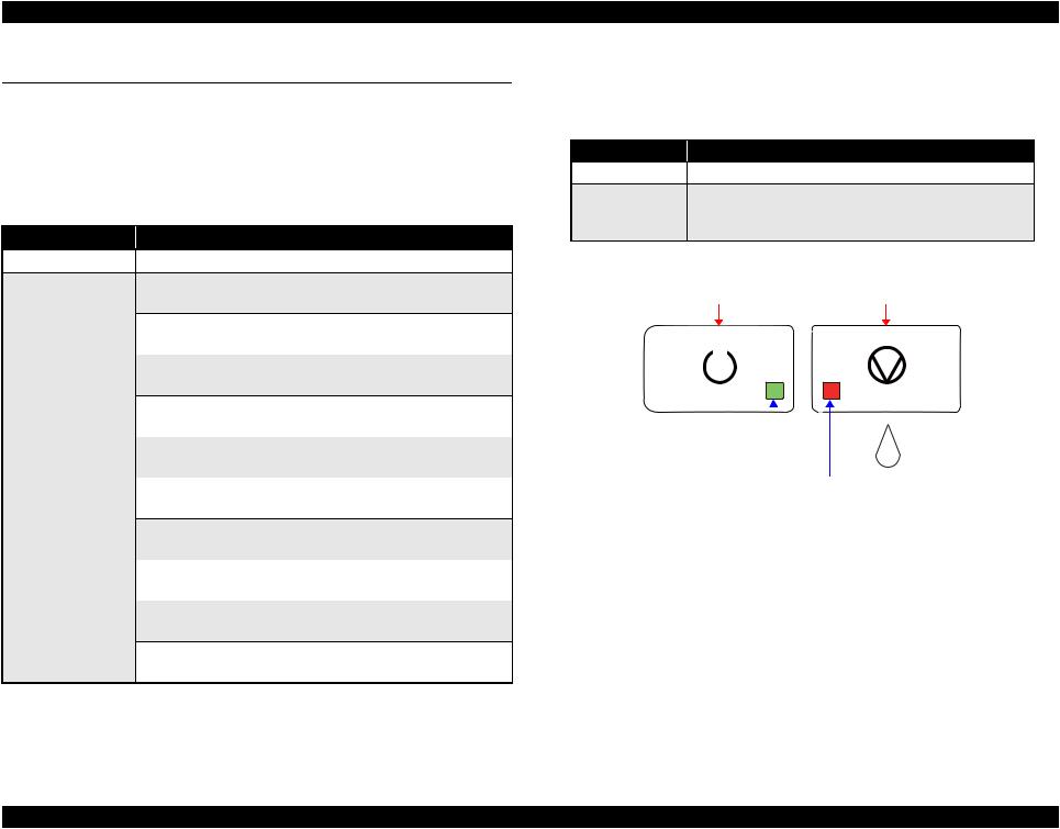
3.2 Troubleshooting With LED Error Indications
LED error display, cause, and remedy are explained here.
Error
Ink end/ No ink cartridge/ Incorrect ink cartridge
Paper Out
Double feed error
Paper jam
Maintenance request (Waste ink overflow)
Fatal error
Note : “---”: no change.
LED status
Power  Maintenance
---On
---On
---On
---On
Flashes alternately
Off |
Flashes fast |
Table 3-1. Troubleshooting With LED Error Indications
Cause |
Remedy |
•Ink inside Bk, Y, M, C cartridges has run out.
•Ink cartridge(s) is not installed.
•Non-genuine ink cartridge(s) is installed.
•Paper loading operation is executed when there is no paper.
•Papers stopped before the PE Sensor or could not be fed.
•Papers are fed without being placed against the right edge guide.
•Connector of the PE sensor is disconnected.
•When performing duplex printing, blank paper is ejected.
•The printer detected that the paper is too long upon ejection.
Even though paper feeding operation is carried out for predetermined times, leading edge or back-end of the paper could not be detected.
As a result of cleaning and flushing, total emission of ink has exceeded the specific level.
•Home position of the carriage could not be detected.
•Abnormal external pressure is applied to the printer when the power is on.
•Carriage movement is interfered during printing.
•Check the ink cartridge(s) and reinstall it correctly.
•Replace the ink cartridge(s) with a genuine one.
1.If there is no paper on the paper tray, load papers.
2.If the paper has stopped halfway, remove the paper, check if the paper is not bent, fan the paper, and load it against the edge guide.
3.Press the [Maintenance] button to release the error.
1.Remove the blank paper, or check the paper size.
2.Press the [Maintenance] button to eject the paper and release the error.
1.Press the [Maintenance] button on the panel.
2.If paper jam occurred again after pressing the button, open the printer cover and remove all the papers inside the printer and papers set on the hopper.
3.Making sure there is no paper inside the printer, load paper on the hopper and press [Maintenance].
Replace the waste ink pad, and reset the waste ink counter using the adjustment program. Refer to Chapter 5 “ADJUSTMENT” (p.69) for details.
1.Turn the power off, wait for a few seconds, and turn the power back on again.
2.If the fatal error still appears, turn the power off, remove the papers on the hopper, and check the following:
•Open the printer cover, check the ink cartridges, and reinstall them correctly.
•Check is there is no foreign material or papers inside the printer. If there is any, remove them.
3. Turn the printer power on.
TROUBLESHOOTING |
Troubleshooting With LED Error Indications |
29 |
Epson Stylus C58/C59/ME 2/C79/D78/C90/C91/C92/D92/T20/T20E/T23/T26/S20/T10/T11/ME 30/T21/T24/T27/S21 |
Revision E |
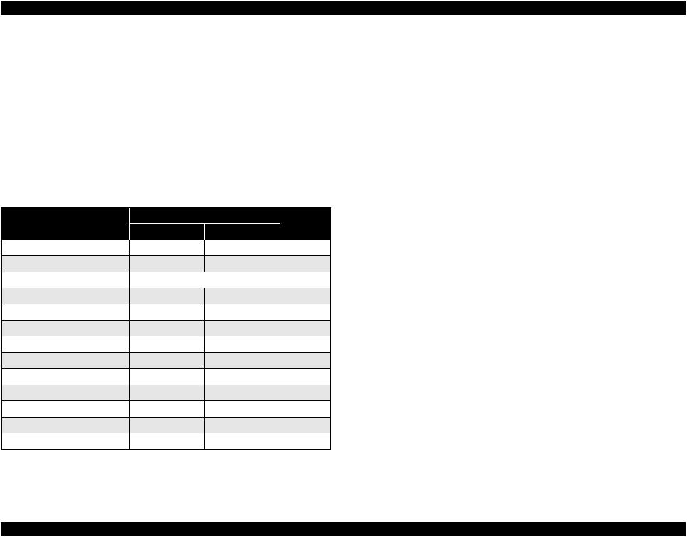
3.3 Troubleshooting for Motors and Sensors
Motor
Table 3-2. Motor Resistance and Check Points
Motor name |
Type |
Location |
Check point |
Resistance |
|
CR motor |
Motor with DC brush |
CN5 |
Pin 1 & 2 |
28.8 Ω ± 10% |
|
PF motor |
4-phase, 200-pole HB stepping motor |
CN6 |
Pin 1 & 3 |
4.3 Ω + 8%/- |
|
Pin 2 & 4 |
12%(20ºC) |
||||
|
|
|
|||
Sensor |
Table 3-3. Sensor Check |
|
|
||
|
|
|
|||
Sensor name |
Detecting system |
Location |
Signal level |
Sensor status |
|
PE sensor |
Transmission photo interrupter |
CN7 pin 1 & 2 |
2.6 V or more |
Paper loaded |
|
0.4 V or less |
No paper |
||||
|
|
|
|||
TROUBLESHOOTING |
Troubleshooting for Motors and Sensors |
30 |
Loading...