


 Loading...
SERVICE MANUAL
Color Inkjet Printer
WorkForce 1100
Epson Stylus Office T1110
Epson Stylus Office B1100
Epson Stylus Office T1100
Epson ME Office 1100
Confidential
SEIJ09-003
Notice:
All rights reserved. No part of this manual may be reproduced, stored in a retrieval system, or transmitted in any form or by any means, electronic, mechanical, photocopying, recording, or otherwise, without the prior written permission of SEIKO EPSON CORPORATION.
The contents of this manual are subject to change without notice.
All effort have been made to ensure the accuracy of the contents of this manual. However, should any errors be detected, SEIKO EPSON would greatly appreciate being informed of them.
The above not withstanding SEIKO EPSON CORPORATION can assume no responsibility for any errors in this manual or the consequences thereof.
EPSON is a registered trademark of SEIKO EPSON CORPORATION.
General Notice: |
Other product names used herein are for identification purpose only and may be trademarks or registered trademarks of their |
|
respective owners. EPSON disclaims any and all rights in those marks. |
Copyright © 2010 SEIKO EPSON CORPORATION.
IJP CS Quality Assurance Department
Confidential
PRECAUTIONS
Precautionary notations throughout the text are categorized relative to 1)Personal injury and 2) damage to equipment.
DANGER |
Signals a precaution which, if ignored, could result in serious or fatal personal injury. Great caution should be exercised in performing procedures preceded by |
|
DANGER Headings. |
WARNING |
Signals a precaution which, if ignored, could result in damage to equipment. |
The precautionary measures itemized below should always be observed when performing repair/maintenance procedures.
DANGER
1.ALWAYS DISCONNECT THE PRODUCT FROM THE POWER SOURCE AND PERIPHERAL DEVICES PERFORMING ANY MAINTENANCE OR REPAIR PROCEDURES.
2.NO WORK SHOULD BE PERFORMED ON THE UNIT BY PERSONS UNFAMILIAR WITH BASIC SAFETY MEASURES AS DICTATED FOR ALL ELECTRONICS TECHNICIANS IN THEIR LINE OF WORK.
3.WHEN PERFORMING TESTING AS DICTATED WITHIN THIS MANUAL, DO NOT CONNECT THE UNIT TO A POWER SOURCE UNTIL INSTRUCTED TO DO SO. WHEN THE POWER SUPPLY CABLE MUST BE CONNECTED, USE EXTREME CAUTION IN WORKING ON POWER SUPPLY AND OTHER ELECTRONIC COMPONENTS.
4.WHEN DISASSEMBLING OR ASSEMBLING A PRODUCT, MAKE SURE TO WEAR GLOVES TO AVOID INJURIER FROM METAL PARTS WITH SHARP EDGES.
WARNING
1.REPAIRS ON EPSON PRODUCT SHOULD BE PERFORMED ONLY BY AN EPSON CERTIFIED REPAIR TECHNICIAN.
2.MAKE CERTAIN THAT THE SOURCE VOLTAGES IS THE SAME AS THE RATED VOLTAGE, LISTED ON THE SERIAL NUMBER/RATING PLATE. IF THE EPSON PRODUCT HAS A PRIMARY AC RATING DIFFERENT FROM AVAILABLE POWER SOURCE, DO NOT CONNECT IT TO THE POWER SOURCE.
3.ALWAYS VERIFY THAT THE EPSON PRODUCT HAS BEEN DISCONNECTED FROM THE POWER SOURCE BEFORE REMOVING OR REPLACING PRINTED CIRCUIT BOARDS AND/OR INDIVIDUAL CHIPS.
4.IN ORDER TO PROTECT SENSITIVE MICROPROCESSORS AND CIRCUITRY, USE STATIC DISCHARGE EQUIPMENT, SUCH AS ANTI-STATIC WRIST STRAPS, WHEN ACCESSING INTERNAL COMPONENTS.
5.REPLACE MALFUNCTIONING COMPONENTS ONLY WITH THOSE COMPONENTS BY THE MANUFACTURE; INTRODUCTION OF SECOND-SOURCE ICs OR OTHER NON-APPROVED COMPONENTS MAY DAMAGE THE PRODUCT AND VOID ANY APPLICABLE EPSON WARRANTY.
6.WHEN USING COMPRESSED AIR PRODUCTS; SUCH AS AIR DUSTER, FOR CLEANING DURING REPAIR AND MAINTENANCE, THE USE OF SUCH PRODUCTS CONTAINING FLAMMABLE GAS IS PROHIBITED.
Confidential

About This Manual
This manual describes basic functions, theory of electrical and mechanical operations, maintenance and repair procedures of the printer. The instructions and procedures included herein are intended for the experienced repair technicians, and attention should be given to the precautions on the preceding page.
Manual Configuration
This manual consists of six chapters and Appendix.
CHAPTER 1.PRODUCT DESCRIPTIONS
Provides a general overview and specifications of the product.
CHAPTER 2.OPERATING PRINCIPLES
Describes the theory of electrical and mechanical operations of the product.
CHAPTER 3.TROUBLESHOOTING
Describes the step-by-step procedures for the troubleshooting.
CHAPTER 4.DISASSEMBLY / ASSEMBLY
Describes the step-by-step procedures for disassembling and assembling the product.
CHAPTER 5.ADJUSTMENT
Provides Epson-approved methods for adjustment.
CHAPTER 6.MAINTENANCE
Provides preventive maintenance procedures and the lists of Epsonapproved lubricants and adhesives required for servicing the product.
APPENDIX Provides the following additional information for reference:
•Connector Summary
•Exploded Diagram
•Parts List
Symbols Used in this Manual
Various symbols are used throughout this manual either to provide additional information on a specific topic or to warn of possible danger present during a procedure or an action. Be aware of all symbols when they are used, and always read NOTE, CAUTION, or WARNING messages.
Indicates an operating or maintenance procedure, practice or condition that is necessary to keep the product’s quality.
Indicates an operating or maintenance procedure, practice, or condition that, if not strictly observed, could result in damage to, or destruction of, equipment.
May indicate an operating or maintenance procedure, practice or condition that is necessary to accomplish a task efficiently. It may also provide additional information that is related to a specific subject, or comment on the results achieved through a previous action.
Indicates an operating or maintenance procedure, practice or condition that, if not strictly observed, could result in injury or loss of life.
Indicates that a particular task must be carried out according to a certain standard after disassembly and before re-assembly, otherwise the quality of the components in question may be adversely affected.
Confidential

|
|
|
Revision Status |
|
|
|
|
Revision |
Date of Issue |
|
Description |
A |
August 7, 2009 |
First Release |
|
|
|
|
|
B |
August 3, 2010 |
Modified the following figures. |
|
|
|
|
Chapter 4 |
|
|
|
4.4.1 APG Assy (p78) |
|
|
|
"4-28 Disconnecting the Cables (p78)" |
|
|
|
4.4.6 ASF Assy (p96) |
|
|
|
"4-83 Releasing the Cables (2) (p97)" |
|
|
|
4.4.9 Front Paper Guide Pad (p103) |
|
|
|
"4-99 Reinstalling the Front Paper Guide Pad (1) (p103)" |
|
|
Disassembling THE FRONT PAPER GUIDE PAD TRAY (p112) |
|
|
|
|
"4-132 Checking the Front Paper Guide Pad (p114)" |
|
|
|
|
C |
August 27, 2010 |
Modified the following figures in the table. |
|
|
|
|
Chapter 3 |
|
|
|
3.1.1 Troubleshooting according to Error Messages (p30) |
|
|
|
"3-11 Troubleshooting of Fatal Error (p41)" |
|
|
|
(p44) Check Point 2, (p46) Check Point 1 |
|
|
Modified the following figure. |
|
|
|
|
Chapter 4 |
|
|
|
4.5.2 PF Motor (p122) |
|
|
|
"4-152 Removing the PF Motor (p122)" |
|
|
|
|
Confidential

WorkForce 1100/Epson Stylus Office T1110/B1100/T1100/Epson ME Office 1100 |
Revision C |
CONTENTS
Chapter 1 Product Description |
|
|
1.1 |
Features.................................................................................................................. |
9 |
1.2 |
Printing Specifications......................................................................................... |
10 |
|
1.2.1 Basic Specifications ................................................................................... |
10 |
|
1.2.2 Ink Cartridge .............................................................................................. |
10 |
|
1.2.3 Print Mode ................................................................................................. |
11 |
|
1.2.4 Supported Paper ......................................................................................... |
13 |
|
1.2.5 Printing Area ............................................................................................. |
16 |
1.3 |
Interface............................................................................................................... |
16 |
1.4 |
General Specifications......................................................................................... |
17 |
|
1.4.1 Electrical Specifications ............................................................................ |
17 |
|
1.4.2 Environmental Conditions ......................................................................... |
17 |
|
1.4.3 Durability ................................................................................................... |
18 |
|
1.4.4 Acoustic Noise ........................................................................................... |
18 |
|
1.4.5 Safety Approvals (Safety standards/EMI) ................................................. |
18 |
1.5 |
Operation Buttons & Indicators (LEDs).............................................................. |
18 |
|
1.5.1 Operation Buttons ...................................................................................... |
18 |
|
1.5.2 Indicators (LEDs) ...................................................................................... |
18 |
|
1.5.3 Operation Buttons & LEDs Functions ...................................................... |
19 |
|
1.5.4 Errors & Remedies .................................................................................... |
20 |
Chapter 2 Operating Principles |
|
|
2.1 |
Overview ............................................................................................................. |
22 |
2.2 |
Printer Mechanism............................................................................................... |
22 |
2.3 |
Printhead Specifications ...................................................................................... |
23 |
2.4 |
PG Setting............................................................................................................ |
24 |
2.5 |
Motors & Sensors ................................................................................................ |
25 |
2.6 |
Power-On Sequence ............................................................................................ |
26 |
2.7 |
Printer Initialization............................................................................................. |
28 |
Chapter 3 Troubleshooting |
|
3.1 Overview ............................................................................................................. |
30 |
3.1.1 Troubleshooting according to Error Messages .......................................... |
30 |
3.1.2 Troubleshooting based on Observed Faults .............................................. |
50 |
Chapter 4 Disassembly And Assembly |
|
4.1 Overview ............................................................................................................. |
62 |
4.1.1 Precautions ................................................................................................ |
62 |
4.1.2 Tools .......................................................................................................... |
63 |
4.1.3 Screws ....................................................................................................... |
63 |
4.1.4 Work Completion Checklist ...................................................................... |
64 |
4.1.5 Locking/Releasing the Carriage ................................................................ |
65 |
4.1.6 Disassembly ............................................................................................... |
66 |
4.2 Removing the Housings ...................................................................................... |
67 |
4.2.1 Paper Support Assy ................................................................................... |
67 |
4.2.2 Stacker Assy .............................................................................................. |
67 |
4.2.3 Front Decoration Plate Left/Right ............................................................. |
68 |
4.2.4 Rear Housing ............................................................................................. |
68 |
4.2.5 Panel Unit .................................................................................................. |
69 |
4.2.6 Decoration Plate Left/Right ....................................................................... |
71 |
4.2.7 Upper Housing / Printer Cover .................................................................. |
72 |
4.2.8 Upper Housing Support Assy .................................................................... |
74 |
4.3 Removing the Boards .......................................................................................... |
75 |
4.3.1 Board Assy (Main Board/Power Supply Board) ....................................... |
75 |
4.4 Disassembling the Printer Mechanism ................................................................ |
78 |
4.4.1 APG Assy .................................................................................................. |
78 |
4.4.2 CR Scale .................................................................................................... |
79 |
4.4.3 Printhead / CSIC Assy ............................................................................... |
81 |
4.4.4 Lower Housing / Printer Mechanism ........................................................ |
86 |
4.4.5 Carriage Shaft / Carriage Unit ................................................................... |
88 |
4.4.6 ASF Assy ................................................................................................... |
96 |
4.4.7 LD Roller ................................................................................................... |
99 |
4.4.8 Retard Roller Assy .................................................................................. |
101 |
6
Confidential

WorkForce 1100/Epson Stylus Office T1110/B1100/T1100/Epson ME Office 1100 |
Revision C |
4.4.9 Front Paper Guide Pad ............................................................................. |
103 |
4.4.10 Waste Ink Pad / Waste Ink Tray Assy ................................................... |
104 |
4.4.11 Foot ........................................................................................................ |
105 |
4.4.12 Paper EJ Frame Assy ............................................................................. |
106 |
4.4.13 Ink System Unit ..................................................................................... |
107 |
4.4.14 Front Paper Guide / Paper EJ Roller / |
|
Front Paper Guide Pad Tray ............................................................................. |
110 |
4.4.15 PF Roller Shaft ...................................................................................... |
115 |
4.4.16 Release Holder Assy .............................................................................. |
117 |
4.4.17 Upper Paper Guide Assys ...................................................................... |
118 |
4.5 Removing the Motors ........................................................................................ |
120 |
4.5.1 CR Motor ................................................................................................. |
120 |
4.5.2 PF Motor .................................................................................................. |
122 |
4.5.3 ASF Motor ............................................................................................... |
123 |
4.6 Removing the Sensors ....................................................................................... |
124 |
4.6.1 CR Encoder ............................................................................................. |
124 |
4.6.2 PF Encoder .............................................................................................. |
124 |
4.6.3 PW Sensor ............................................................................................... |
125 |
4.6.4 PE Sensor Holder .................................................................................... |
126 |
4.6.5 Cover Open Sensor .................................................................................. |
127 |
Chapter 5 Adjustment |
|
5.1 Adjustment Items and Overview ....................................................................... |
129 |
5.1.1 Servicing Adjustment Item List ............................................................... |
129 |
5.1.2 Required Adjustments ............................................................................. |
133 |
5.1.3 Required Adjustment Tools ..................................................................... |
135 |
5.2 Adjustment Using Adjustment Program ........................................................... |
136 |
5.2.1 Head angular adjustment ......................................................................... |
136 |
5.2.2 PW Adjustment/First Dot Position Adjustment ...................................... |
137 |
5.2.3 Bi-D adjustment ....................................................................................... |
138 |
5.2.4 BAND printing adjustment ...................................................................... |
139 |
5.2.5 PF adjustment .......................................................................................... |
140 |
5.2.6 PF band adjustment ................................................................................. |
141 |
5.3 Adjustment without Using Adjustment Program .............................................. |
141 |
5.3.1 PF Belt Tension Adjustment ................................................................... |
141 |
5.3.2 PG Adjustment ........................................................................................ |
143 |
5.3.3 PF Roller Shaft Center Support Position Adjustment ............................. |
146 |
|
5.3.4 How to Adjust the PF Roller Shaft Center |
|
|
Support Position ............................................................................................... |
147 |
|
5.3.5 ASF Guide Roller LDs Position Adjustment .......................................... |
150 |
Chapter 6 Maintenance |
|
|
6.1 |
Overview ........................................................................................................... |
153 |
|
6.1.1 Cleaning ................................................................................................... |
153 |
|
6.1.2 Service Maintenance ............................................................................... |
153 |
|
6.1.3 Lubrication .............................................................................................. |
155 |
Chapter 7 Appendix |
|
|
7.1 |
Connector Summary.......................................................................................... |
163 |
7.2 |
Exploded Diagram / Parts List .......................................................................... |
163 |
7
Confidential

C H A P T E R
1
PRODUCT DESCRIPTION
Confidential
WorkForce 1100/Epson Stylus Office T1110/B1100/T1100/Epson ME Office 1100 |
Revision C |
1.1 Features
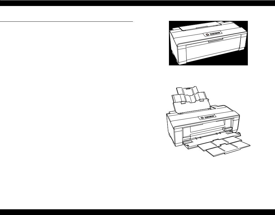
WorkForce 1100/Epson Stylus Office T1110/B1100/T1100/Epson ME Office 1100 is a color ink-jet printer that supports A3+ size.
The main features are;
High speed & High quality
Maximum print resolution: 5760 (H) x 1440 (V) dpi
F3-3 Mach Turbo II Printhead achieves higher black&white print speed than ever.
Installs two black ink cartridges as standard.
High-speed borderless printing is available.
One USB ports for PC connection
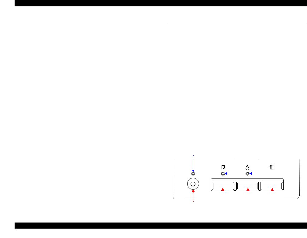
Control panel
Simple design with four buttons and three indicators (LED).
Dimensions
Dimensions: 616 mm (W) x 322 mm (D) x 214 mm (H)
(Paper support and stacker are closed. Rubber feet are included)
Weight: |
12 kg (without ink cartridges) |
Paper Support & Stacker are Closed
Paper Support & Stacker are Opened
Figure 1-1. External View
Product Description |
Features |
9 |
|
|
Confidential |
WorkForce 1100/Epson Stylus Office T1110/B1100/T1100/Epson ME Office 1100 |
Revision C |
1.2 |
Printing Specifications |
|
||
1.2.1 |
Basic Specifications |
|
||
|
|
Table 1-1. Printer Specifications |
||
|
|
|
|
|
|
Item |
|
|
Specifications |
|
|
|
|
|
Print method |
|
On-demand ink jet |
|
|
|
|
|
|
|
Nozzle configuration |
|
Black: 180 nozzles x 2 |
|
|
|
|
|
Color: 59 nozzles x 3 (Cyan, Magenta, Yellow) |
|
|
|
|
||
Print direction |
|
Bi-directional minimum distance printing, unidirectional printing |
||
|
|
|
||
Print resolution |
|
Horizontal x Vertical (dpi) |
||
|
|
|
• 360 x 180 |
• 1440 x 720 |
|
|
|
• 360 x 360 |
• 720 x 1440 |
|
|
|
• 360 x 720 |
• 5760 x 1440 |
|
|
|
• 720 x 720 |
|
Control code |
|
• ESC/P Raster command |
||
|
|
|
• EPSON Remote command |
|
Input buffer size |
|
T.B.D. Kbytes |
|
|
|
|
|
||
Paper feed method |
|
Friction feed, using one ASF (Auto Sheet Feeder) |
||
|
|
|
|
|
Paper path |
|
2-way feed |
|
|
|
|
|
||
Paper feed rates |
|
170 msec. (at 25.4 mm feed) (T.B.D.) |
||
|
|
|
||
PF interval |
|
Programmable in 0.01764 mm (1/1440 inch) steps |
||
|
|
|
|
|
1.2.2 Ink Cartridge
The product numbers of the EPSON ink cartridges for this printer are shown below.
Table 1-2. Product No. of Ink Cartridges
Color |
EAI |
Latin |
Euro |
CISMEA/ |
ECC |
|
Asia |
||||||
|
|
|
|
|
||
|
|
|
|
|
|
|
Black |
T0681 (S) |
T1151 (S) |
T0711H (S) |
T0731H (S) |
T1191 (S) |
|
T0691 (2S) |
T1091(2S) |
|||||
|
|
|
|
|||
|
|
|
|
|
|
|
Cyan |
T0682 (2S) |
T1032 (S) |
T1002 (S) |
T1032 (S) |
T1232 (S) |
|
T0692 (3S) |
T1092 (2S) |
|||||
|
|
|
|
|||
|
|
|
|
|
|
|
Magenta |
T0683 (2S) |
T1033 (S) |
T1003 (S) |
T1033 (S) |
T1233 (S) |
|
T0693 (3S) |
T1093 (2S) |
|||||
|
|
|
|
|||
|
|
|
|
|
|
|
Yellow |
T0684 (2S) |
T1034 (S) |
T1004 (S) |
T1034 (S) |
T1234 (S) |
|
T0694 (3S) |
T1094 (2S) |
|||||
|
|
|
|
|||
|
|
|
|
|
|
Shelf life
Two years from production date (if unopened), six months after opening package.
Storage Temperature
Table 1-3. Storage Temperature
Situation |
Storage Temperature |
Limit |
|
When stored in individual boxes |
-20 oC to 40 oC |
|
|
(-4oF to 104oF) |
|
||
|
1 month max. at 40 oC (104oF) |
||
When installed in main unit |
-20 oC to 40 oC |
||
|
|||
(-4oF to 104oF) |
|
||
|
|
Dimension
12.7 mm (W) x 68 mm (D) x 47 mm (H)
CAUTION |
|
The ink cartridge cannot be refilled. |
|
|
Do not use expired ink cartridges. |
The ink in the ink cartridge freezes at -16 °C (3.2 oF). It takes
about three hours under 25 °C (77oF) until the ink thaws and becomes usable.
Product Description |
Printing Specifications |
10 |
Confidential
WorkForce 1100/Epson Stylus Office T1110/B1100/T1100/Epson ME Office 1100 |
Revision C |
1.2.3 Print Mode
Table 1-4. Print Mode (Color)
Media |
Resolution |
Dot Size |
Bi-d |
Micro |
||
Mode |
(H x V) dpi |
(cps*1) |
Weave |
|||
|
|
|||||
• Plain paper |
Draft 1 |
360x180 |
Eco |
ON |
OFF |
|
• Premium Bright White Paper |
(400cps) |
|||||
|
|
|
|
|||
(EAI) |
|
|
|
|
|
|
Draft 2 |
360x180 |
Eco |
ON |
OFF |
||
• Bright White Inkjet Paper |
||||||
(400cps) |
||||||
|
|
|
|
|||
(others) |
|
|
|
|
|
|
Normal 2 |
360x360 |
VSD1 |
ON |
OFF |
||
|
||||||
|
(320cps) |
|||||
|
|
|
|
|
||
|
|
|
|
|
|
|
|
Fine |
360x720 |
VSD2 |
ON |
ON |
|
|
(245cps) |
|||||
|
|
|
|
|
||
|
|
|
|
|
|
|
|
Photo 2 |
720x720 |
VSD3 |
ON |
ON |
|
|
(245cps) |
|||||
|
|
|
|
|
||
|
|
|
|
|
|
|
• Ultra Premium Glossy Photo |
Best Photo 2 |
720x1440 |
VSD3 |
ON |
ON |
|
Paper (EAI) |
(245cps) |
|||||
|
|
|
|
|||
• Ultra Glossy Photo Paper |
|
|
|
|
|
|
Photo RPM |
5760x1440 |
VSD3 |
ON |
ON |
||
(others) |
||||||
(245cps) |
||||||
|
|
|
|
|
||
|
|
|
|
|
|
|
• Premium Photo Paper Glossy |
Fine |
360x720 |
VSD2 |
ON |
ON |
|
(EAI) |
(245cps) |
|||||
|
|
|
|
|||
• Premium Glossy Photo Paper |
|
|
|
|
|
|
Photo1 |
720x720 |
VSD2 |
ON |
ON |
||
(others) |
(245cps) |
|||||
|
|
|
|
|
|
|
|
Best Photo 2 |
720x1440 |
VSD3 |
ON |
ON |
|
|
(245cps) |
|||||
|
|
|
|
|
||
|
|
|
|
|
|
|
|
Photo RPM |
5760x1440 |
VSD3 |
ON |
ON |
|
|
(245cps) |
|||||
|
|
|
|
|
||
|
|
|
|
|
|
|
• Photo Paper Glossy (EAI) |
Fine |
360x720 |
VSD2 |
ON |
ON |
|
• Glossy Photo Paper (others) |
(245cps) |
|||||
|
|
|
|
|||
• Premium Photo Paper Semi- |
|
|
|
|
|
|
Photo 1 |
720x720 |
VSD2 |
ON |
ON |
||
Gloss (EAI) |
(245cps) |
|||||
|
|
|
|
|||
• Premium Semigloss Photo |
|
|
|
|
|
|
Best Photo 2 |
720x1440 |
VSD3 |
ON |
ON |
||
Paper (others) |
||||||
(245cps) |
||||||
|
|
|
|
|
||
|
|
|
|
|
|
Table 1-4. Print Mode (Color)
|
Media |
Resolution |
Dot Size |
Bi-d |
Micro |
||
|
Mode |
(H x V) dpi |
(cps*1) |
Weave |
|||
|
|
|
|||||
• Premium Presentation Paper |
Photo 1 |
720x720 |
VSD2 |
ON |
ON |
||
Matte (EAI) |
(245cps) |
||||||
|
|
|
|
||||
• Matte Paper - Heavyweight |
|
|
|
|
|
||
|
|
|
|
|
|||
(others) |
|
Best Photo 1 |
1440x720 |
VSD3 |
ON |
ON |
|
• Photo Quality Inkjet Paper |
(245cps) |
||||||
|
|
|
|
||||
(others)*2 |
|
|
|
|
|
||
• Envelope |
Normal 2 |
360x360 |
VSD1 |
OFF |
OFF |
||
|
|
(320cps) |
|||||
|
|
|
|
|
|
||
|
|
|
|
|
|
|
|
|
|
Fine |
360x720 |
VSD2 |
OFF |
ON |
|
|
|
(245cps) |
|||||
|
|
|
|
|
|
||
|
|
|
|
|
|
||
Note : The default is indicated by boldface. |
|
|
|
|
|||
Note *1: |
cps = character per second |
|
|
|
|
||
*2: |
Not supported in EAI. |
|
|
|
|
|
|
Product Description |
Printing Specifications |
11 |
Confidential

WorkForce 1100/Epson Stylus Office T1110/B1100/T1100/Epson ME Office 1100 |
Revision C |
Table 1-5. Print Mode (Monochrome)
Media |
Resolution |
Dot Size |
Bi-d |
Micro |
||
Mode |
(H x V) dpi |
(cps*1) |
Weave |
|||
|
|
|||||
• Plain paper |
Draft 3 |
360x360 |
Eco |
ON |
OFF |
|
• Premium Bright White Paper |
(400cps) |
|||||
|
|
|
|
|||
(EAI) |
|
|
|
|
|
|
Draft 4 |
360x360 |
Eco |
ON |
OFF |
||
• Bright White Inkjet Paper |
||||||
(400cps) |
||||||
|
|
|
|
|||
(others) |
|
|
|
|
|
|
Normal 1 |
360x360 |
VSD1 |
ON |
OFF |
||
|
||||||
|
(320cps) |
|||||
|
|
|
|
|
||
|
|
|
|
|
|
|
|
Fine |
360x720 |
VSD2 |
ON |
ON |
|
|
(245cps) |
|||||
|
|
|
|
|
||
|
|
|
|
|
|
|
|
Photo 2 |
720x720 |
VSD3 |
ON |
ON |
|
|
(245cps) |
|||||
|
|
|
|
|
||
|
|
|
|
|
|
|
• Ultra Premium Glossy Photo |
Best Photo 2 |
720x1440 |
VSD3 |
ON |
ON |
|
Paper (EAI) |
(245cps) |
|||||
|
|
|
|
|||
• Ultra Glossy Photo Paper |
|
|
|
|
|
|
Photo RPM |
5760x1440 |
VSD3 |
ON |
ON |
||
(others) |
||||||
(245cps) |
||||||
|
|
|
|
|
||
|
|
|
|
|
|
|
• Premium Photo Paper Glossy |
Fine |
360x720 |
VSD2 |
ON |
ON |
|
(EAI) |
(245cps) |
|||||
|
|
|
|
|||
• Premium Glossy Photo Paper |
|
|
|
|
|
|
Photo1 |
720x720 |
VSD2 |
ON |
ON |
||
(others) |
(245cps) |
|||||
|
|
|
|
|
|
|
|
Best Photo 2 |
720x1440 |
VSD3 |
ON |
ON |
|
|
(245cps) |
|||||
|
|
|
|
|
||
|
|
|
|
|
|
|
|
Photo RPM |
5760x1440 |
VSD3 |
ON |
ON |
|
|
(245cps) |
|||||
|
|
|
|
|
||
|
|
|
|
|
|
|
• Photo Paper Glossy (EAI) |
Fine |
360x720 |
VSD2 |
ON |
ON |
|
• Glossy Photo Paper (others) |
(245cps) |
|||||
|
|
|
|
|||
• Premium Photo Paper Semi- |
|
|
|
|
|
|
Photo 1 |
720x720 |
VSD2 |
ON |
ON |
||
Gloss (EAI) |
(245cps) |
|||||
|
|
|
|
|||
• Premium Semigloss Photo |
|
|
|
|
|
|
Best Photo 2 |
720x1440 |
VSD3 |
ON |
ON |
||
Paper (others) |
||||||
(245cps) |
||||||
|
|
|
|
|
||
|
|
|
|
|
|
Table 1-5. Print Mode (Monochrome)
|
Media |
Resolution |
Dot Size |
Bi-d |
Micro |
||
|
Mode |
(H x V) dpi |
(cps*1) |
Weave |
|||
|
|
|
|||||
• Premium Presentation Paper |
Photo 1 |
720x720 |
VSD2 |
ON |
ON |
||
Matte (EAI) |
(245cps) |
||||||
|
|
|
|
||||
• Matte Paper - Heavyweight |
|
|
|
|
|
||
|
|
|
|
|
|||
(others) |
|
Best Photo 1 |
1440x720 |
VSD3 |
ON |
ON |
|
• Photo Quality Inkjet Paper |
(245cps) |
||||||
|
|
|
|
||||
(others)*2 |
|
|
|
|
|
||
• Envelope |
Normal 1 |
360x360 |
VSD1 |
OFF |
OFF |
||
|
|
(320cps) |
|||||
|
|
|
|
|
|
||
|
|
|
|
|
|
|
|
|
|
Fine |
360x720 |
VSD2 |
OFF |
ON |
|
|
|
(245cps) |
|||||
|
|
|
|
|
|
||
|
|
|
|
|
|
||
Note : The default is indicated by boldface. |
|
|
|
|
|||
Note *1: |
cps = character per second |
|
|
|
|
||
*2: |
Not supported in EAI. |
|
|
|
|
|
|
Product Description |
Printing Specifications |
12 |
Confidential

WorkForce 1100/Epson Stylus Office T1110/B1100/T1100/Epson ME Office 1100 |
Revision C |
1.2.4 Supported Paper
The table below lists the paper type and sizes supported by the printer. The Supported paper type and sizes vary depending on destinations (between EAI, EUR, and Asia).
Table 1-6. Supported Paper
Paper Name |
|
Paper Size |
Thickness |
Weight |
EAI |
EUR |
Asia |
|||||
|
mm |
g/m2 |
lb. |
P*1 |
B*2 |
P*1 |
B*2 |
P*1 |
B*2 |
|||
|
|
|
||||||||||
|
A3+/SuperA3 |
329 x 483 mm |
|
|
|
Y |
- |
Y |
- |
Y |
- |
|
|
|
|
|
|
|
|
|
|
|
|
|
|
|
A3 |
297 x 420 mm |
|
|
|
Y |
- |
Y |
- |
Y |
- |
|
|
|
|
|
|
|
|
|
|
|
|
|
|
|
US B |
279.4 x 431.8 mm (11” x 17”) |
|
|
|
Y |
- |
- |
- |
- |
- |
|
|
|
|
|
|
|
|
|
|
|
|
|
|
|
B4 |
257 x 364 mm |
|
|
|
Y |
- |
Y |
- |
Y |
- |
|
|
|
|
|
|
|
|
|
|
|
|
|
|
|
Legal |
215.9 x 355.6 mm (8.5” x 14”) |
|
|
|
Y |
- |
Y |
- |
Y |
- |
|
|
|
|
|
|
|
|
|
|
|
|
|
|
Plain paper |
Letter |
215.9 x 279.4 mm (8.5” x 11”) |
0.08-0.11 |
64-90 |
17-24 |
Y |
- |
Y |
- |
Y |
- |
|
|
|
|
|
|
|
|
|
|||||
A4 |
210 x 297 mm (8.3” x 11.7”) |
Y |
- |
Y |
- |
Y |
- |
|||||
|
|
|
|
|||||||||
|
|
|
|
|
|
|
|
|
|
|
|
|
|
B5 |
182 x 257 mm (7.2” x 10.1”) |
|
|
|
- |
- |
Y |
- |
Y |
- |
|
|
|
|
|
|
|
|
|
|
|
|
|
|
|
A5 |
148 x 210 mm (5.8” x 8.3”) |
|
|
|
- |
- |
Y |
- |
Y |
- |
|
|
|
|
|
|
|
|
|
|
|
|
|
|
|
Half Letter |
139.7 x 215.9 mm (5.5” x 8.5”) |
|
|
|
Y |
- |
- |
- |
- |
- |
|
|
|
|
|
|
|
|
|
|
|
|
|
|
|
A6 |
105 x 148 mm (4.1” x 5.8”) |
|
|
|
Y |
- |
Y |
- |
Y |
- |
|
|
|
|
|
|
|
|
|
|
|
|
|
|
|
User Defined |
50.8 x 127329 x 1117.6 mm |
|
|
|
Y |
- |
Y |
- |
Y |
- |
|
|
|
|
|
|
|
|
|
|
|
|
|
|
Premium Inkjet Plain Paper |
A4 |
210 x 297 mm (8.3” x 11.7”) |
0.11 |
80 |
21 |
- |
- |
Y |
- |
Y |
- |
|
|
|
|
|
|
|
|
|
|
|
|
|
|
Premium Bright White Paper |
Letter |
215.9 x 279.4 mm (8.5” x 11”) |
0.11 |
90 |
24 |
Y |
- |
- |
- |
- |
- |
|
|
|
|
|
|
|
|
|
|
|
|
|
|
Bright White Inkjet Paper |
A3 |
297 x 420 mm |
0.13 |
92.5 |
25 |
- |
- |
Y |
- |
Y |
- |
|
|
|
|
|
|
|
|
|
|||||
A4 |
210 x 297 mm (8.3” x 11.7”) |
- |
- |
Y |
- |
Y |
- |
|||||
|
|
|
|
|||||||||
|
|
|
|
|
|
|
|
|
|
|
|
|
|
Letter |
215.9 x 279.4 mm (8.5” x 11”) |
|
|
|
Y |
Y |
- |
- |
- |
- |
|
|
|
|
|
|
|
|
|
|
|
|
|
|
|
A4 |
210 x 297 mm (8.3” x 11.7”) |
|
|
|
- |
- |
Y |
Y |
Y |
Y |
|
Ultra Premium Glossy Photo Paper (EAI) |
|
|
|
|
|
|
|
|
|
|
|
|
8” x 10” |
203.2 x 254 mm |
0.3 |
290 |
77 |
Y |
Y |
- |
- |
- |
- |
||
Ultra Glossy Photo Paper (others) |
||||||||||||
|
|
|
|
|
|
|
|
|
|
|
||
|
5” x 7” |
127 x 178 mm |
|
|
|
Y |
Y |
Y |
Y |
- |
- |
|
|
|
|
|
|
|
|
|
|
|
|
|
|
|
4” x 6” |
101.6 x 152.4 mm |
|
|
|
Y |
Y |
Y |
Y |
Y |
Y |
|
|
|
|
|
|
|
|
|
|
|
|
|
|
Product Description Printing Specifications 13
Confidential

WorkForce 1100/Epson Stylus Office T1110/B1100/T1100/Epson ME Office 1100 |
|
|
|
|
|
|
|
Revision C |
||||
|
|
Table 1-6. Supported Paper |
|
|
|
|
|
|
|
|
|
|
|
|
|
|
|
|
|
|
|
|
|
|
|
Paper Name |
|
Paper Size |
Thickness |
Weight |
EAI |
EUR |
Asia |
|||||
|
mm |
g/m2 |
lb. P*1 B*2 |
P*1 |
B*2 |
P*1 |
B*2 |
|||||
|
|
|
||||||||||
|
A3+/SuperA3 |
329 x 483 mm |
|
|
|
Y |
|
Y |
Y |
Y |
Y |
Y |
|
|
|
|
|
|
|
|
|
|
|
|
|
|
A3 |
297 x 420 mm |
|
|
|
Y |
|
Y |
Y |
Y |
Y |
Y |
|
|
|
|
|
|
|
|
|
|
|
|
|
|
11” x 14” |
279.4 x 355.6 mm |
|
|
|
Y |
|
Y |
- |
- |
- |
- |
|
|
|
|
|
|
|
|
|
|
|
|
|
|
US B |
279.4 x 431.8 mm (11” x 17”) |
|
|
|
Y |
|
Y |
- |
- |
- |
- |
|
|
|
|
|
|
|
|
|
|
|
|
|
Premium Photo Paper Glossy (EAI) |
Letter |
215.9 x 279.4 mm (8.5” x 11”) |
0.27 |
255 |
68 |
Y |
|
Y |
- |
- |
- |
- |
|
|
|
|
|
|
|
|
|
||||
Premium Glossy Photo Paper (others) |
|
|
|
|
|
|
|
|
|
|||
A4 |
210 x 297 mm (8.3” x 11.7”) |
Y |
|
Y |
Y |
Y |
Y |
Y |
||||
|
|
|
|
|||||||||
|
|
|
|
|
||||||||
|
|
|
|
|
|
|
|
|
|
|
|
|
|
8” x 10” |
203.2 x 254 mm |
|
|
|
Y |
|
Y |
- |
- |
- |
- |
|
|
|
|
|
|
|
|
|
|
|
|
|
|
5” x 7” |
127 x 178 mm |
|
|
|
Y |
|
Y |
Y |
Y |
Y |
Y |
|
|
|
|
|
|
|
|
|
|
|
|
|
|
4” x 6” |
101.6 x 152.4 mm |
|
|
|
Y |
|
Y |
Y |
Y |
Y |
Y |
|
|
|
|
|
|
|
|
|
|
|
|
|
|
16:9 wide |
102 x 181 mm (4” x 7.11”) |
|
|
|
Y |
|
Y |
Y |
Y |
Y |
Y |
|
|
|
|
|
|
|
|
|
|
|
|
|
|
A3+/SuperA3 |
329 x 483 mm |
|
|
|
Y |
|
Y |
- |
- |
- |
- |
|
|
|
|
|
|
|
|
|
|
|
|
|
|
US B |
279.4 x 431.8 mm (11” x 17”) |
|
|
|
Y |
|
Y |
- |
- |
- |
- |
|
|
|
|
|
|
|
|
|
|
|
|
|
Photo Paper Glossy (EAI) |
Letter |
215.9 x 279.4 mm (8.5” x 11”) |
0.25 |
258 |
68 |
Y |
|
Y |
- |
- |
- |
- |
|
|
|
|
|
|
|
|
|
||||
Glossy Photo Paper (others) |
|
|
|
|
|
|
|
|
|
|||
A4 |
210 x 297 mm (8.3” x 11.7”) |
Y |
|
Y |
Y |
Y |
Y |
Y |
||||
|
|
|
|
|||||||||
|
|
|
|
|
||||||||
|
|
|
|
|
|
|
|
|
|
|
|
|
|
5” x 7” |
127 x 178 mm |
|
|
|
- |
|
- |
Y |
Y |
- |
- |
|
|
|
|
|
|
|
|
|
|
|
|
|
|
4” x 6” |
101.6 x 152.4 mm |
|
|
|
Y |
|
Y |
Y |
Y |
Y |
Y |
|
|
|
|
|
|
|
|
|
|
|
|
|
|
A3+/SuperA3 |
329 x 483 mm |
|
|
|
Y |
|
Y |
Y |
Y |
Y |
Y |
|
|
|
|
|
|
|
|
|
|
|
|
|
|
A3 |
297 x 420 mm |
|
|
|
Y |
|
Y |
Y |
Y |
Y |
Y |
|
|
|
|
|
|
|
|
|
|
|
|
|
Premium Photo Paper Semi-gloss (EAI) |
US B |
279.4 x 431.8 mm (11” x 17”) |
0.27 |
250 |
66 |
Y |
|
Y |
- |
- |
- |
- |
Premium Semigloss Photo Paper (others) |
|
|
|
|
|
|
|
|
|
|||
Letter |
215.9 x 279.4 mm (8.5” x 11”) |
Y |
|
Y |
- |
- |
- |
- |
||||
|
|
|
|
|||||||||
|
|
|
|
|
|
|
|
|
|
|
|
|
|
A4 |
210 x 297 mm (8.3” x 11.7”) |
|
|
|
- |
|
- |
Y |
Y |
Y |
Y |
|
|
|
|
|
|
|
|
|
|
|
|
|
|
4” x 6” |
101.6 x 152.4 mm |
|
|
|
Y |
|
Y |
Y |
Y |
Y |
Y |
|
|
|
|
|
|
|
|
|
|
|
|
|
Product Description |
Printing Specifications |
14 |
Confidential

WorkForce 1100/Epson Stylus Office T1110/B1100/T1100/Epson ME Office 1100 |
|
|
|
|
|
|
|
|
Revision C |
||||||
|
|
|
|
Table 1-6. Supported Paper |
|
|
|
|
|
|
|
|
|
|
|
|
|
|
|
|
|
|
|
|
|
|
|
|
|
|
|
|
Paper Name |
|
|
Paper Size |
Thickness |
Weight |
|
EAI |
EUR |
Asia |
|||||
|
|
|
mm |
g/m2 |
lb. |
P*1 B*2 |
P*1 |
B*2 |
P*1 |
B*2 |
|||||
|
|
|
|
|
|
||||||||||
|
|
11” x 14” |
|
279.4 x 355.6 mm |
|
|
|
Y |
|
Y |
- |
- |
- |
- |
|
|
|
|
|
|
|
|
|
|
|
|
|
|
|
|
|
Premium Presentation Paper Matte (EAI) |
Letter |
|
215.9 x 279.4 mm (8.5” x 11”) |
0.23 |
167 |
44 |
Y |
|
Y |
- |
- |
- |
- |
||
|
|
|
|
|
|
|
|
|
|
|
|||||
Matte Paper Heavy-weight (others) |
|
|
|
|
|
|
|
|
|
|
|
||||
A4 |
|
210 x 297 mm (8.3” x 11.7”) |
Y |
|
Y |
Y |
Y |
Y |
Y |
||||||
|
|
|
|
|
|||||||||||
|
|
|
|
|
|
|
|||||||||
|
|
|
|
|
|
|
|
|
|
|
|
|
|
|
|
|
|
8” x 10” |
|
203.2 x 254 mm |
|
|
|
Y |
|
Y |
- |
- |
- |
- |
|
|
|
|
|
|
|
|
|
|
|
|
|
|
|
|
|
|
|
A3+/SuperA3 |
|
329 x 483 mm |
|
|
|
Y |
|
- |
Y |
- |
Y |
- |
|
|
|
|
|
|
|
|
|
|
|
|
|
|
|
|
|
Presentation Paper Matte (EAI) |
A3 |
|
297 x 420 mm |
0.12 |
102 |
27 |
- |
|
- |
Y |
- |
Y |
- |
||
|
|
|
|
|
|
|
|
|
|
|
|||||
Photo Quality Inkjet Paper/ESF (others) |
|
|
|
|
|
|
|
|
|
|
|
||||
US B |
|
279.4 x 431.8 mm (11” x 17”) |
Y |
|
- |
- |
- |
- |
- |
||||||
|
|
|
|
|
|||||||||||
|
|
|
|
|
|
|
|||||||||
|
|
|
|
|
|
|
|
|
|
|
|
|
|
|
|
|
|
A4 |
|
210 x 297 mm (8.3” x 11.7”) |
|
|
|
- |
|
- |
Y |
- |
Y |
- |
|
|
|
|
|
|
|
|
|
|
|
|
|
|
|
|
|
|
|
#10 |
|
104.8 x 241.3 mm (4.125” x 9.5”) |
|
|
|
Y |
|
- |
Y |
- |
Y |
- |
|
|
|
|
|
|
|
|
|
|
|
|
|
|
|
|
|
Envelopes |
|
#DL |
|
110 x 220 mm |
- |
75- |
20-27 |
- |
|
- |
Y |
- |
Y |
- |
|
|
|
|
|
|
|
|
|
|
|
|
|
||||
|
|
|
|
|
100 |
|
|
|
|
|
|
|
|||
|
#C4 |
|
229 x 324 mm |
- |
|
- |
Y |
- |
Y |
- |
|||||
|
|
|
|
|
|
||||||||||
|
|
|
|
|
|
|
|||||||||
|
|
|
|
|
|
|
|
|
|
|
|
|
|
|
|
|
|
#C6 |
|
114 x 162 mm |
|
|
|
- |
|
- |
Y |
- |
Y |
- |
|
|
|
|
|
|
|
|
|
|
|
|
|
|
|
|
|
Photo Quality Self Adheshive Sheet |
A4 |
|
210 x 297 mm (8.3” x 11.7”) |
0.19 |
167 |
44 |
Y |
|
- |
Y |
- |
Y |
- |
||
|
|
|
|
|
|
|
|
|
|
|
|
|
|
|
|
Note *1: “Y” in the “P” column stands for “the paper type/size is Supported”. |
|
|
|
|
|
|
|
|
|
|
|
|
|||
*2: “Y” in the “B” column stands for “Borderless printing is available”. |
|
|
|
|
|
|
|
|
|
|
|
|
|||
|
|
|
|
|
|
|
|
|
|
|
|
|
|||
CAUTION |
Make sure the paper is not wrinkled, fluffed, torn, or folded. |
|
|
|
|
|
|
|
|
|
|
||||
|
The curve of paper must be 5 mm or below. |
|
|
|
|
|
|
|
|
|
|
|
|
||
When printing on an envelope, be sure the flap is folded neatly.
Do not use the adhesive envelopes.
Do not use double envelopes and cellophane window envelopes.
Product Description |
Printing Specifications |
15 |
Confidential
WorkForce 1100/Epson Stylus Office T1110/B1100/T1100/Epson ME Office 1100 |
Revision C |
1.2.5 |
Printing Area |
|
|
|
|
|
|
|
|
|
|
|
|
|
|
|
|
|
|
|
|
|
|
|
|
|
|
|
|
||||||||||||||||
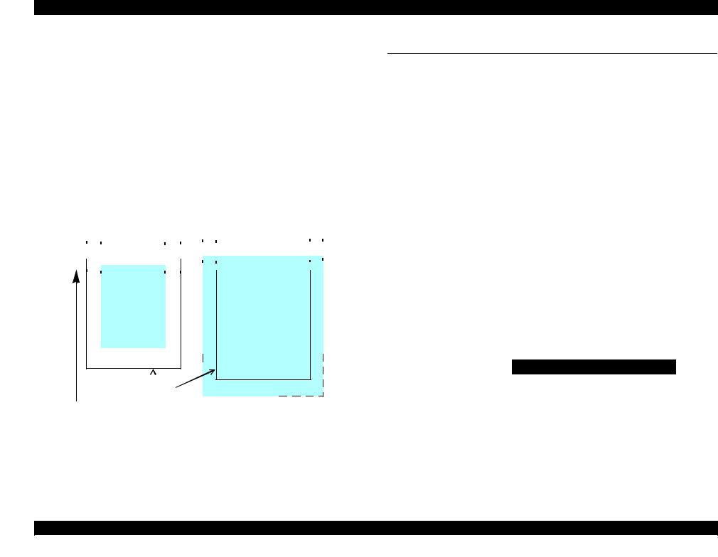
The printing area for this printer is shown below. |
|
|
|
|
|
|
|
|
|
|
|
|
|
|
|
|
|
|
|
|
|||||||||||||||||||||||||
|
|
|
|
|
|
|
|
|
Table 1-7. Printing Area (Margins) |
|
|
|
|
|
|
|
|
|
|
|
|||||||||||||||||||||||||
|
|
|
|
|
|
|
|
|
|
|
|
|
|
|
|
|
|
|
|
|
|
|
|
|
|
|
|
|
|
|
|
|
|
|
|
|
|
|
|
|
|
|
|
|
|
Print Mode |
|
|
|
|
Paper Size |
|
|
|
|
|
|
|
|
|
|
|
|
|
Margin* |
|
|
|
|
|
|||||||||||||||||||||
|
|
|
|
|
|
|
Left |
|
|
Right |
|
Top |
|
|
|
|
Bottom |
||||||||||||||||||||||||||||
|
|
|
|
|
|
|
|
|
|
|
|
|
|
|
|
|
|
|
|
|
|
|
|
|
|
|
|
||||||||||||||||||
|
|
|
|
|
|
|
|
|
|
|
|
|
|
|
|
|
|
|
|
|
|
|
|
|
|
|
|
|
|
|
|
|
|
|
|
|
|
|
|
|
|
|
|
|
|
Standard print |
|
Any size |
|
|
|
3 mm |
|
|
3 mm |
|
|
3 mm |
|
|
|
|
3 mm |
||||||||||||||||||||||||||||
|
|
|
|
|
|
|
|
|
|
|
|
|
|
|
|
|
|
|
|
|
|
|
|
|
|
|
|
|
|
|
|
|
|
|
|
|
|
|
|
|
|
|
|
|
|
|
|
|
|
Envelopes |
|
|
|
5 mm |
|
|
5 mm |
|
|
5 mm |
|
|
|
|
20 mm |
||||||||||||||||||||||||||
|
|
|
|
|
|
|
|
|
|
|
|
|
|
|
|
|
|
|
|
|
|
|
|
|
|
|
|
|
|
|
|
|
|
|
|
|
|
|
|
|
|
|
|
|
|
Borderless |
|
A4/Letter to 5” x 7”/ |
|
|
2.54 mm |
|
2.54 mm |
|
2.96 mm |
|
|
|
|
4.02 mm |
|||||||||||||||||||||||||||||||
|
|
|
16:9 wide |
|
|
|
|
|
|
|
|
|
|||||||||||||||||||||||||||||||||
|
|
|
|
|
|
|
|
|
|
|
|
|
|
|
|
|
|
|
|
|
|
|
|
|
|
|
|
|
|
|
|||||||||||||||
|
|
|
|
|
|
|
|
|
|
|
|
|
|
|
|
|
|
|
|
|
|
|
|
|
|
|
|
|
|
|
|
|
|
|
|
|
|
|
|
|
|
|
|
|
|
|
|
|
|
4” x 6” |
|
|
|
2.54 mm |
|
2.54 mm |
|
1.34 mm |
|
|
|
|
2.54 mm |
||||||||||||||||||||||||||||
|
|
|
|
|
|
|
|
|
|
|
|
|
|
|
|
|
|
|
|
|
|
|
|
|
|
|
|
|
|
|
|
|
|
|
|
|
|
|
|
|
|
|
|||
Note * : |
The margins for Borderless print are margins that bleed off the edges of paper. |
||||||||||||||||||||||||||||||||||||||||||||
|
|
|
|
Cut Sheet (Standard) |
|
|
|
|
|
Cut Sheet (Borderless) |
|
|
|
|
|
||||||||||||||||||||||||||||||
|
|
|
LM |
RM |
|
LM |
|
|
|
|
|
|
|
|
|
|
|
|
|
|
|
RM |
|||||||||||||||||||||||
|
|
|
|
|
|
|
|
|
|
|
|
|
|
|
|
|
|
|
|
|
|
|
|
|
|
|
|
|
|
|
|
|
|
|
|
|
|
|
|
|
|
|
|
|
|
|
|
|
|
|
|
|
|
|
|
|
|
|
|
|
|
|
|
|
|
|
|
|
|
|
|
|
|
|
|
|
|
|
|
|
|
|
|
|
|
|
|
|
|
|
|
|
|
|
|
|
|
|
|
|
TM |
|
|
|
|
|
|
|
|
|
|
|
|
|
|
|
|
|
|
|
TM |
|
|
|
|
|
|
|
|
|
|
|
|||||
|
|
|
|
|
|
|
|
|
|
|
|
|
|
|
|
|
|
|
|
|
|
|
|
|
|
|
|
|
|
|
|
|
|
|
|
|
|
|
|
|
|
|
|
|
|
|
|
|
|
|
|
|
Print Area |
|
|
|
|
|
|
|
|
|
|
|
|
Print Area |
|
|
|
|
|
||||||||||||||||||||
|
|
|
|
|
|
|
|
|
|
|
|
|
|
|
|
|
|
|
|
|
|
|
|
||||||||||||||||||||||
|
|
|
|
|
|
|
|
|
|
|
|
|
|
|
|
|
|
|
|
|
|
|
|
||||||||||||||||||||||
|
|
|
|
|
|
|
|
|
|
|
|
|
|
|
|
|
|
|
|
|
|
|
|
||||||||||||||||||||||
|
|
|
|
|
|
|
|
|
|
|
|
|
|
|
|
|
|
|
|
|
|
|
|
||||||||||||||||||||||
|
|
|
|
|
|
|
|
|
|
|
|
|
|
|
|
|
|
|
|
|
|
|
|
||||||||||||||||||||||
|
|
|
|
|
|
|
|
|
|
|
|
|
|
|
|
|
|
|
|
|
|
|
|
||||||||||||||||||||||
|
|
|
|
|
|
|
|
|
|
|
|
|
|
|
|
|
|
|
|
|
|
|
|
||||||||||||||||||||||
|
|
|
|
|
|
|
|
|
|
|
|
|
|
|
|
|
|
|
|
|
|
|
|
|
|
|
|
|
|
|
|
|
|
|
|
|
|
|
|
|
|
|
|
|
|
|
|
|
|
|
|
|
|
|
|
|
|
|
|
|
|
|
|
|
|
|
|
|
|
|
|
|
|
|
|
|
|
|
|
|
|
|
|
|
|
|
|
|
|
|
|
|
|
|
|
|
|
|
|
|
|
|
|
|
|
|
|
|
|
|
|
|
|
|
|
|
|
|
|
|
|
|
|
|
|
|
|
|
|
|
|
|
|
|
|
|
|
|
|
|
|
|
|
|
|
|
|
|
|
|
|
|
|
|
|
|
|
|
|
|
|
|
|
|
|
|
|
|
|
|
|
|
|
|
|
|
|
|
|
|
|
|
|
|
|
|
|
|
|
|
|
|
|
|
|
|
|
|
|
|
|
|
|
|
|
|
|
|
|
|
|
|
|
|
|
|
|
|
|
|
|
|
|
|
|
|
|
|
|
|
|
|
|
|
|
|
|
|
|
|
|
|
|
|
|
|
|
|
|
|
|
|
|
|
|
|
|
|
|
|
|
|
|
|
|
|
|
|
|
|
|
|
|
|
|
|
|
|
|
|
|
|
|
|
|
|
|
|
|
|
|
|
|
|
|
|
|
|
|
|
|
|
|
|
|
|
|
|
|
|
|
|
|
|
|
|
|
|
|
|
|
BM
|
|
|
|
|
|
|
|
|
|
|
|
BM |
||
|
|
|
|
|
|
|
|
|
|
|
|
|||
|
|
|
|
|
|
|
|
|
|
|
|
|||
|
|
|
|
|
|
|
|
|
|
|
|
|||
Paper |
Size |
|
||||||||||||
|
||||||||||||||
|
|
|
|
|
|
|
|
|
|
|
|
|
|
|
Paper Feed Direction
Figure 1-2. Printing Area
1.3 Interface
This printer is equipped with the USB device port on the rear of the printer for connecting with a host such as a computer. The following is the specifications of the port.
Specification:
Universal Serial Bus Specifications Revision 2.0
Universal Serial Bus Device Class Definition for Printing Devices Version 1.1
Transfer rate: |
480 Mbps (High Speed Device) |
||
Data format: |
NRZI |
|
|
Compatible connector: |
USB Series B |
||
Max. cable length: |
2 [m] or less |
|
|
|
Table 1-8. Device ID |
||
|
|
|
|
When IEEE 1284.4 is Enabled |
When IEEE 1284.4 is Disabled |
||
|
|
|
|
@EJL<SP>ID<CR><LF> |
|
|
@EJL<SP>ID<CR><LF> |
MFG:EPSON; |
|
|
MFG:EPSON; |
CMD:ESCPL2,BDC,D4,D4PX; |
|
|
CMD:ESCPL2,BDC; |
MDL:Model Name; |
|
|
MDL:Model Name; |
CLS:PRINTER; |
|
|
CLS:PRINTER; |
DES:EPSON<SP>Model Name; |
|
|
DES:EPSON<SP>Model Name; |
CID:EpsonStd5; |
|
|
CID:EpsonStd5; |
|
|
|
|
The “Model Name” is replaced as shown in the following table.
Destination |
Model Name |
|
|
North America |
WorkForce 1100 |
|
|
Latin America |
Epson Stylus Office T1110 |
|
|
Euro |
Epson Stylus Office B1100 |
|
|
Asia/CISMEA |
Epson Stylus Office T1100 |
|
|
China |
Epson ME OFFICE 1100 |
|
|
Product Description |
Interface |
16 |
Confidential
WorkForce 1100/Epson Stylus Office T1110/B1100/T1100/Epson ME Office 1100 |
Revision C |
1.4 General Specifications
1.4.1 Electrical Specifications
Primary power input
Table 1-9. Primary Power Specifications
|
|
Item |
100-120V model |
220-240V model |
Rated power supply voltage |
100 to 120 VAC |
220 to 240 VAC |
||
|
|
|
||
Input voltage range |
90 to 132 VAC |
198 to 264 VAC |
||
|
|
|
|
|
Rated current |
|
0.7 A (max. 1.5 A) |
0.4 A (max. 0.6 A) |
|
|
|
|
|
|
Rated frequency |
|
50 to 60 Hz |
||
|
|
|||
Input frequency range |
49.5 to 60.5 Hz |
|||
|
|
|||
Insulation resistance |
AC1000Vrms (for one minute) |
|||
|
|
|||
Energy conservation |
International Energy Star Program compliant |
|||
|
|
|
|
|
Power |
|
Printing |
Approx. 26 W |
Approx. 26 W |
|
|
|
|
|
|
Sleep mode |
Approx. 1.3 W |
Approx. 1.7 W |
|
consumption |
|
|||
|
|
|
|
|
|
|
Standby mode (power-off) |
Approx. 0.2 W |
Approx. 0.4 W |
|
|
|
|
|
Note : If the printer is not operated for more than three minutes, it goes into sleep mode within five minutes.
1.4.2 Environmental Conditions
Table 1-10. Environmental Conditions
Condition |
Temperature*1 |
Humidity*1,2 |
Shock |
Vibration |
|
Operating |
10 to 35°C |
20 to 80% |
1G |
0.15G, |
|
(50 to 95°F) |
(1 msec. or less) |
10 to 55Hz |
|||
|
|
||||
|
|
|
|
|
|
Storage*3 |
-20 to 40°C*4 |
5 to 85% |
2G |
0.50G, |
|
(unpacked) |
(-4°F to 104°F) |
(2 msec. or less) |
10 to 55Hz |
||
|
|||||
|
|
|
|
|
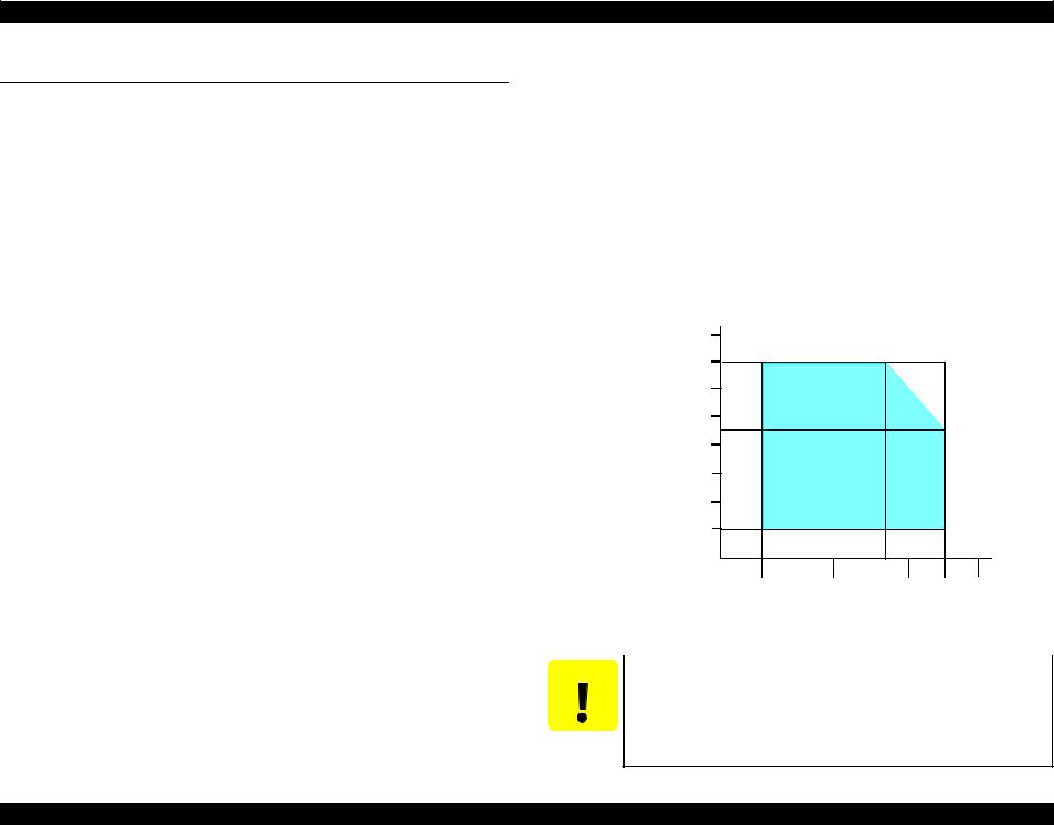
Note *1: The combined Temperature and Humidity conditions must be within the blue-shaded range in Figure 1-3.
*2: No condensation
*3: Non-operating with unpacked.
*4: Must be less than 1 month under 40°C.
90 |
|
|
|
|
80 |
|
|
|
|
70 |
|
|
|
|
60 |
|
|
|
|
Humidity (%) |
|
|
|
|
50 |
|
|
|
|
40 |
|
|
|
|
30 |
|
|
|
|
20 |
|
|
|
|
|
|
27/80 |
|
|
10/50 |
20/68 |
30/86 |
35/95 |
40/104 |
Temperature (°C/°F)
|
Figure 1-3. Temperature/Humidity Range |
|
|
CAUTION |
When returning the repaired printer to the customer, make sure |
|
the Printhead is covered with the cap and the ink cartridge is |
|
installed. |
If the Printhead is not covered with the cap when the printer is off, turn on the printer with the ink cartridge installed, make sure the Printhead is covered with the cap, and then turn the printer off.
Product Description |
General Specifications |
17 |
Confidential
WorkForce 1100/Epson Stylus Office T1110/B1100/T1100/Epson ME Office 1100 |
Revision C |
1.4.3 |
Durability |
|
|
||
|
|
|
|
|
|
|
Item |
Durability |
Remark |
||
|
|
|
|
|
|
|
|
Black |
|
36,000 pages, or five years |
A4, 3.5% duty (ECMA) |
|
|
|
whichever comes first |
||
Total print life |
|
|
|
||
|
|
|
|
||
Color |
|
18,000 pages, or five years |
Plain Paper A4, ISO24712 |
||
|
|
|
|||
|
|
|
whichever comes first |
Pattern, Default Mode print |
|
|
|
|
|
||
|
|
|
|
|
|
|
Printhead |
|
Six billions shots (per nozzle) or |
--- |
|
|
|
five years whichever comes first |
|||
|
|
|
|
|
|
|
|
|
|
|
|
1.4.4 |
Acoustic Noise |
|
|||
35 dB (when printing from PC, on Premium Glossy Photo Paper, in highest quality)
1.4.5 Safety Approvals (Safety standards/EMI)
USA |
UL60950-1 |
|
FCC Part15 Subpart B Class B |
Canada |
CAN/CSA-C22.2 No.60950-1 |
|
CAN/CSA-CEI/IEC CISPR 22 Class B |
Mexico |
NOM-019-SCFI-1998 |
Taiwan |
CNS13438 Class B |
|
CNS14336 (IEC60950) |
EU |
EN60950-1 |
|
EN55022 Class B |
|
EN61000-3-2, EN61000-3-3 |
|
EN55024 |
Germany |
EN60950-1 |
Russia |
GOST-R (IEC60950-1, CISPR 22) |
Singapore |
IEC60950-1 |
Korea |
K60950-1 |
|
KN22 Class B |
|
KN61000-4-2/-3/-4/-5/-6/-11 |
China |
GB4943 |
|
GB9254 Class B, GB17625.1 |
Argentina |
IEC60950-1 |
Australia |
AS/NZS CISPR22 Class B |
Hong Kong |
IEC60950-1 |
1.5 Operation Buttons & Indicators (LEDs)
1.5.1 Operation Buttons
The printer has the following four operation buttons.
|
Table 1-11. Operation Buttons |
|
|
Button |
Function |
Power |
Turns the power ON/OFF. |
|
|
Paper |
Feeds or ejects paper. |
|
|
Ink |
Runs a sequence of ink cartridge replacement or cleaning. |
|
|
Cancel |
Cancels job during printing |
|
|
1.5.2 Indicators (LEDs)
Three indicators (LEDs) are provided to indicate settings or printer status.
|
Table 1-12. Indicators (LEDs) |
|
|
LED |
Function |
|
Lights at power-on. |
Power LED (green) |
Flashes during some sequence is in progress. |
|
Flashes at high speed during power-OFF sequence. |
|
|
Paper LED (red) |
Lights or flashes when an paper-related error occurs.* |
|
|
Ink LED (red) |
Lights or flashes when an ink-related error occurs.* |
|
|
Note * : See Table 1-14 ?Indicators (LEDs) Function? for the LED status at error occurrence.
Power LED |
Paper LED |
Ink LED |
|||||
|
|
|
|
|
|
|
|
|
|
|
|
|
|
|
|
|
|
|
|
|
|
|
|
Power Button |
Paper |
|
Button |
Ink |
|
Button Cancel |
|
Button |
|
|
|
Figure 1-4. Buttons & LEDs
Product Description |
Operation Buttons & Indicators (LEDs) |
18 |
Confidential
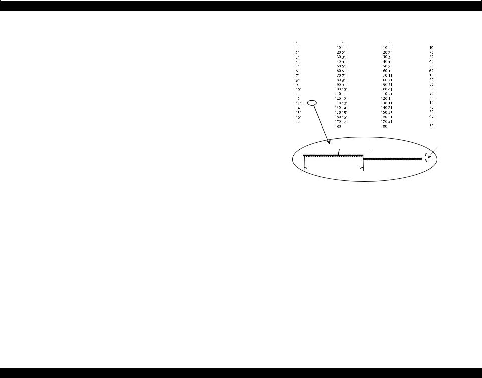
WorkForce 1100/Epson Stylus Office T1110/B1100/T1100/Epson ME Office 1100 |
Revision C |
1.5.3 Operation Buttons & LEDs Functions
Black1 Black2
Detailed information on the buttons and LEDs functions are listed below.
|
Table 1-13. Operation Button Functions |
|
|
|
|
|
|
|
|
|
|
|
|
|
|
|
|
|
|
|
|
|
|
|
|
|
|
|
|
|
|
|
|
|
|
|
Yellow |
|
|
|
|
|
|
|
|
|
|
|
|
|
|
|
|
|
|
|
|
|
|
|
|
|
|
|
|
|
|
|
|
|
|
|
|
|
|||
Button |
Printer |
Function |
|
|
|
|
|
|
|
|
|
|
|
|
|
|
|
|
|
|
|
|
|
|
|
|
|
|
|
|
|
|
|
|
|
|
|
|
|
Status |
|
|
|
|
|
|
|
|
|
|
|
|
|
|
|
|
|
|
|
|
|
|
|
|
|
|
|
|
|
|
|
|
|
|
|
|
|
Power |
Off |
• Turns the power on. |
|
|
|
|
|
|
|
|
|
|
|
|
|
|
|
|
|
|
|
|
|
|
|
|
|
|
|
|
|
|
|
|
|
|
|
Magenta |
|
On |
• Turns the power off. |
|
|
|
|
|
|
|
|
|
|
|
|
|
|
|
|
|
|
|
|
|
|
|
|
|
|
|
|
|
|
|
|
|
|
|
|
|
|
• Feeds or ejects paper. |
|
|
|
|
|
|
|
|
|
|
|
|
|
|
|
|
|
|
|
|
|
|
|
|
|
|
|
|
|
|
|
|
|
|
|
|
|
|
• Recovers from a multi-feed error and feeds paper to |
|
|
|
|
|
|
|
|
|
|
|
|
|
|
|
|
|
|
|
|
|
|
|
|
|
|
|
|
|
|
|
|
|
|
|
Cyan |
|
|
restart the print job. |
|
|
|
|
|
|
|
|
|
|
|
|
|
|
|
|
|
|
|
|
|
|
|
|
|
|
|
|
|
|
|
|
|
|
|
|
|
|
• Feeds paper when paper is loaded after a no-paper |
|
|
|
|
|
|
|
|
|
|
|
|
|
|
|
|
|
|
|
|
|
|
|
|
|
|
|
|
|
|
|
|
|
|
|
|
|
|
error occurs. |
|
|
|
|
|
|
|
|
|
|
|
|
|
360 dpi VSD1 |
|
|
0.142 mm (1/180 inch) |
|||||||||||||||||||
Paper |
On |
• Ejects a jammed paper when a paper jam error occurs. |
|
|
|
|
|
|
|
|
|
|
|
|
|
|
|
|||||||||||||||||||||
|
|
|
|
|
|
|
|
|
|
|
|
|
|
|
|
|
|
|||||||||||||||||||||
|
|
• Runs a sequence of ink cartridge replacement when |
|
|
|
|
|
|
|
|
|
|
|
|
|
|
|
|
|
|
|
|
|
|
|
|
|
|
|
|
|
|
|
|
|
|
|
|
|
|
|
|
|
|
|
|
|
|
|
|
|
|
|
|
|
|
|
|
|
|
|
|
|
|
|
|
|
|
|
|
|
|
|
|
|
|
|
|
|
|
|
|
|
|
|
|
|
|
32 dots |
|
|
|
|
|
||||||||||||||||||||||
|
|
an ink-out error occurs. The carriage moves to set the |
|
|
|
|
|
|
|
|
|
|
|
|
|
|
||||||||||||||||||||||
|
|
|
|
|
|
|
|
|
|
|
|
|
|
|
|
|||||||||||||||||||||||
|
|
|
|
|
|
|
|
|
|
|
|
|
|
|
|
|||||||||||||||||||||||
|
|
ink cartridge to the position for replacement. |
|
|
|
|
|
|
|
|
|
|
|
|
|
|
|
|
|
|
|
|
|
|
|
|
|
|
|
|
|
|
|
|
|
|
|
|
|
|
|
|
|
|
|
|
|
|
|
|
|
|
|
|
|
|
|
|
|
|
|
|
|
|
|
|
|
|
|
|
|
|
|
|
|
|
|
|
|
• When the carriage has been set in the ink replacement |
|
|
|
|
|
|
|
|
|
|
|
|
|
|
|
|
|
|
|
|
|
|
|
|
|
|
|
|
|
|
|
|
|
|
|
|
|
|
position, moves the carriage to the home position. |
Note : |
The numbers shown in the figure are nozzle numbers. The numbers and color names |
||||||||||||||||||||||||||||||||||
|
|
|
||||||||||||||||||||||||||||||||||||
|
|
• Runs a sequence of ink cartridge replacement. The |
|
are not printed on an actual nozzle check pattern. |
|
|
|
|
|
|||||||||||||||||||||||||||||
|
|
carriage moves to set the ink cartridge to the position |
|
|
|
|
|
|
|
Figure 1-5. Nozzle Check Pattern |
|
|
|
|
|
|||||||||||||||||||||||
Ink |
On |
for replacement. |
|
|
|
|
|
|
|
|
|
|
|
|
||||||||||||||||||||||||
|
|
|
|
|
|
|
|
|
|
|
|
|
|
|
|
|
|
|
|
|
|
|
|
|
|
|
|
|
|
|
|
|
|
|
|
|||
|
|
• When an ink cartridge has been set in the ink replacement |
|
|
|
|
|
|
|
|
|
|
|
|
|
|
|
|
|
|
|
|
|
|
|
|
|
|
|
|
|
|
|
|
|
|
|
|
|
|
position, moves the carriage to the home position. |
|
|
|
|
|
|
|
|
|
|
|
|
|
|
|
|
|
|
|
|
|
|
|
|
|
|
|
|
|
|
|
|
|
|
|
|
|
|
|
|
|
|
|
|
|
|
|
|
|
|
|
|
|
|
|
|
|
|
|
|
|
|
|
|
|
|
|
|
|
|
|
|
|
|
|
Ink |
|
• Runs a head cleaning. |
|
|
|
|
|
|
|
|
|
|
|
|
|
|
|
|
|
|
|
|
|
|
|
|
|
|
|
|
|
|
|
|
|
|
|
|
|
• Runs a sequence of ink cartridge replacement when |
|
|
|
|
|
|
|
|
|
|
|
|
|
|
|
|
|
|
|
|
|
|
|
|
|
|
|
|
|
|
|
|
|
|
|
|
|
(when held for three |
On |
|
|
|
|
|
|
|
|
|
|
|
|
|
|
|
|
|
|
|
|
|
|
|
|
|
|
|
|
|
|
|
|
|
|
|
|
|
ink level low, ink out, or no ink cartridge error has |
|
|
|
|
|
|
|
|
|
|
|
|
|
|
|
|
|
|
|
|
|
|
|
|
|
|
|
|
|
|
|
|
|
|
|
|
||
seconds or longer) |
|
|
|
|
|
|
|
|
|
|
|
|
|
|
|
|
|
|
|
|
|
|
|
|
|
|
|
|
|
|
|
|
|
|
|
|
|
|
|
occurred. |
|
|
|
|
|
|
|
|
|
|
|
|
|
|
|
|
|
|
|
|
|
|
|
|
|
|
|
|
|
|
|
|
|
|
|
|
|
|
|
|
|
|
|
|
|
|
|
|
|
|
|
|
|
|
|
|
|
|
|
|
|
|
|
|
|
|
|
|
|
|
|
|
|
|
|
|
|
|
|
|
|
|
|
|
|
|
|
|
|
|
|
|
|
|
|
|
|
|
|
|
|
|
|
|
|
|
|
|
|
|
|
|
|
|
|
|
|
• Cancels the print job during printing. |
|
|
|
|
|
|
|
|
|
|
|
|
|
|
|
|
|
|
|
|
|
|
|
|
|
|
|
|
|
|
|
|
|
|
|
|
Cancel |
On |
• When the carriage has been set in the ink replacement |
|
|
|
|
|
|
|
|
|
|
|
|
|
|
|
|
|
|
|
|
|
|
|
|
|
|
|
|
|
|
|
|
|
|
|
|
|
|
position, moves the carriage to the home position. |
|
|
|
|
|
|
|
|
|
|
|
|
|
|
|
|
|
|
|
|
|
|
|
|
|
|
|
|
|
|
|
|
|
|
|
|
|
|
|
|
|
|
|
|
|
|
|
|
|
|
|
|
|
|
|
|
|
|
|
|
|
|
|
|
|
|
|
|
|
|
|
|
|
|
|
Power + Ink |
On |
• Forcefully turns the power off. |
|
|
|
|
|
|
|
|
|
|
|
|
|
|
|
|
|
|
|
|
|
|
|
|
|
|
|
|
|
|
|
|
|
|
|
|
(combination) |
|
|
|
|
|
|
|
|
|
|
|
|
|
|
|
|
|
|
|
|
|
|
|
|
|
|
|
|
|
|
|
|
|
|
|
|
|
|
|
|
|
|
|
|
|
|
|
|
|
|
|
|
|
|
|
|
|
|
|
|
|
|
|
|
|
|
|
|
|
|
|
|
|
|
|
|
|
|
|
|
|
|
|
|
|
|
|
|
|
|
|
|
|
|
|
|
|
|
|
|
|
|
|
|
|
|
|
|
|
|
|
|
|
|
|
|
Power + Paper |
At power on |
• Prints a nozzle check pattern* when not connected to |
|
|
|
|
|
|
|
|
|
|
|
|
|
|
|
|
|
|
|
|
|
|
|
|
|
|
|
|
|
|
|
|
|
|
|
|
(combination) |
the PC. |
|
|
|
|
|
|
|
|
|
|
|
|
|
|
|
|
|
|
|
|
|
|
|
|
|
|
|
|
|
|
|
|
|
|
|
|
|
|
|
|
|
|
|
|
|
|
|
|
|
|
|
|
|
|
|
|
|
|
|
|
|
|
|
|
|
|
|
|
|
|
|
|
|
|
||
|
|
|
|
|
|
|
|
|
|
|
|
|
|
|
|
|
|
|
|
|
|
|
|
|
|
|
|
|
|
|
|
|
|
|
|
|
|
|
Note * : The nozzle check pattern printed by the printer is shown in Figure 1-5.
Product Description |
Operation Buttons & Indicators (LEDs) |
19 |
Confidential

WorkForce 1100/Epson Stylus Office T1110/B1100/T1100/Epson ME Office 1100 |
Revision C |
Table 1-14. Indicators (LEDs) Function
Printer Status |
|
Indicators (LEDs) |
Pri- |
|||
Power |
|
Paper |
Ink |
ority*1 |
||
|
|
|||||
Power OFF |
Flashes at |
|
OFF |
OFF |
1 |
|
high speed |
||||||
|
|
|
|
|||
|
|
|
|
|
|
|
Fatal error |
OFF |
|
Flashes at |
Flashes at |
2 |
|
|
high speed |
high speed |
||||
|
|
|
|
|||
|
|
|
|
|
|
|
Maintenance request |
OFF |
|
Flashes |
Flashes |
3 |
|
|
alternately 1 |
alternately 2 |
||||
|
|
|
|
|||
|
|
|
|
|
|
|
Paper jam error |
-- |
|
Flashes |
-- |
4 |
|
|
|
|
|
|
||
Cover open error |
-- |
|
Flashes |
-- |
||
|
|
|||||
|
|
|
|
|
|
|
Multi-feed error |
-- |
|
ON |
-- |
5 |
|
|
|
|
|
|
||
No paper error |
-- |
|
ON |
-- |
||
|
|
|||||
|
|
|
|
|
|
|
Ink cartridge replacement is in progress |
Flashes |
|
-- |
-- |
6 |
|
|
|
|
|
|
|
|
Ink sequence is in progress |
Flashes |
|
-- |
-- |
7 |
|
|
|
|
|
|
|
|
CSIC error |
-- |
|
-- |
ON |
8 |
|
|
|
|
|
|
||
No ink cartridge error or ink-out error |
-- |
|
-- |
ON |
||
|
|
|||||
|
|
|
|
|
|
|
Ink level low |
-- |
|
-- |
Flashes |
9 |
|
|
|
|
|
|
|
|
Power ON |
Flashes |
|
-- |
-- |
10 |
|
|
|
|
|
|
|
|
Reset request*2 |
ON |
|
ON |
ON |
-- |
|
Note *1: |
When two or more errors occur at the same time, the one with higher priority will be indicated. |
|
*2: The all LEDs light for 0.2 seconds when a reset request is received. |
||
Note : |
--: |
No change |
|
Flash: |
Repeats turning On and Off every 1.25 seconds. |
|
Flash at high speed: Repeats turning On and Off every 0.5 seconds. |
|
|
Flashes alternately 1: Same as the “Flash” |
|
|
Flashes alternately 2: Repeats turning Off and On every 1.25 seconds. |
|
1.5.4 Errors & Remedies
Table 1-15. Errors & Remedies
Error |
Error |
Remedies |
|
|
|
|
|
Fatal error |
A mechanical error has occurred. |
Turn the power Off and back it On. |
|
|
|
|
|
Maintenance |
Waste ink pads need to be |
Replace the waste ink pads and reset |
|
request |
replaced. |
the counter. |
|
|
|
|
|
Paper jam |
A paper jam has occurred. |
Remove the jammed paper and press |
|
|
the Paper button. |
||
|
|
||
|
|
|
|
No paper |
Failed to feed paper. |
Load paper correctly and press the |
|
|
Paper button. |
||
|
|
||
|
|
|
|
Multi-feed |
Multiple sheets of paper were fed |
Press the Paper button to eject the |
|
at the same time. |
multiple sheets. |
||
|
|||
|
|
|
|
Ink-out |
The cartridge has run out of ink. |
Replace the cartridge with a new one. |
|
|
|
|
|
No ink cartridge |
Ink cartridge(s) was not detected. |
Replace the cartridge with a new one. |
|
|
|
|
|
Wrong ink |
Incorrect ink cartridge(s) was |
Replace the cartridge with the correct |
|
cartridge |
detected. |
one. |
|
|
|
|
|
Cover open error |
Printing was executed with the |
Close the Printer Cover. |
|
Printer Cover open. |
|
||
|
|
||
|
|
|
Note : For more information on the remedies, see ?3.1.1 Troubleshooting according to Error Messages? (p.30).
Product Description |
Operation Buttons & Indicators (LEDs) |
20 |
Confidential
C H A P T E R
2
OPERATING PRINCIPLES
Confidential

WorkForce 1100/Epson Stylus Office T1110/B1100/T1100/Epson ME Office 1100 |
Revision C |
2.1 Overview
This chapter explains the operating principles of the mechanical sections and electrical circuits in this product. The main components of this product are as follows.
Board Name |
Model Number |
Control circuit board |
CA58 MAIN |
|
|
Power supply circuit board |
C698 PSB/PSE |
|
|
Control panel board |
C698 PNL |
|
|
Relay Board |
CA58 SUB-B |
|
|
CR Relay Board |
CA58 SUB |
|
|
2.2 Printer Mechanism
Like the conventional model, this product uses DC motors and stepping motors as power sources. The following table describes the motor types and their applications.
|
|
Table 2-1. Motors |
|
|
|
|
|
Motor Name |
Type |
|
Applications/Functions |
CR Motor |
DC motor with |
|
Used for carriage driving. Makes little noise during |
|
driving. The CR linear scale and CR encoder sensor |
||
brushes |
|
||
|
|
are used to control the motor. |
|
|
|
|
|
|
|
|
|
|
|
|
Drives the Paper loading rollers at the time of fixed- |
|
DC motor with |
|
value paper loading or paper feed/eject operation. To |
PF Motor |
|
grasp the paper feed pitch, the precision gear surface |
|
brushes |
|
||
|
|
is fitted with the PF scale and the PF encoder sensor |
|
|
|
|
|
|
|
|
is used to control the motor. |
|
|
|
|
APG Motor |
DC motor with |
|
Drives the Carriage Unit at the time of PG setting. |
|
The two APG Sensors are driven vertically to control |
||
brushes |
|
||
|
|
the motor. |
|
|
|
|
|
|
|
|
|
|
4-phase, 48-pole |
|
Drives the paper feed operation of the ASF. Since |
ASF Motor |
PM type stepping |
|
this is a stepping motor, any scales or photo sensors |
|
motor |
|
to know the driving conditions are not required. |
|
|
|
|
|
4-phase, 48-pole |
|
Drives the pump, wiper, etc. of the Ink System. Since |
Pump Motor |
PM type stepping |
|
this is a stepping motor, any scales or photo sensors |
|
motor |
|
to know the driving conditions are not required. |
The basic mechanism is almost same as the Epson Stylus Photo R1900. The schematic diagram below shows the printer mechanism.
PF Encoder |
|
PF Scale |
|
PF Motor |
Sensor |
|
|
|
|
Front Paper |
APG Sensors |
|
Eject Roller |
||
|
||
Rear Paper |
APG Motor |
|
Eject Roller |
||
PF Roller |
APF Sensor |
|
|
||
CR Scale |
|
|
Cover Open |
Timing Belt |
|
Sensor |
CR Encoder |
|
|
Sensor |
|
PW Sensor |
LD Roller |
|
|
||
Carriage |
|
|
Unit |
Retard |
|
|
Roller |
|
Ink System |
PE Sensor |
|
Unit |
||
Pump Motor |
ASF Motor |
|
|
||
Carriage |
CR Motor |
|
Shaft |
|
Figure 2-1. Printer Mechanism Outline
Operating Principles |
Overview |
22 |
|
|
Confidential |
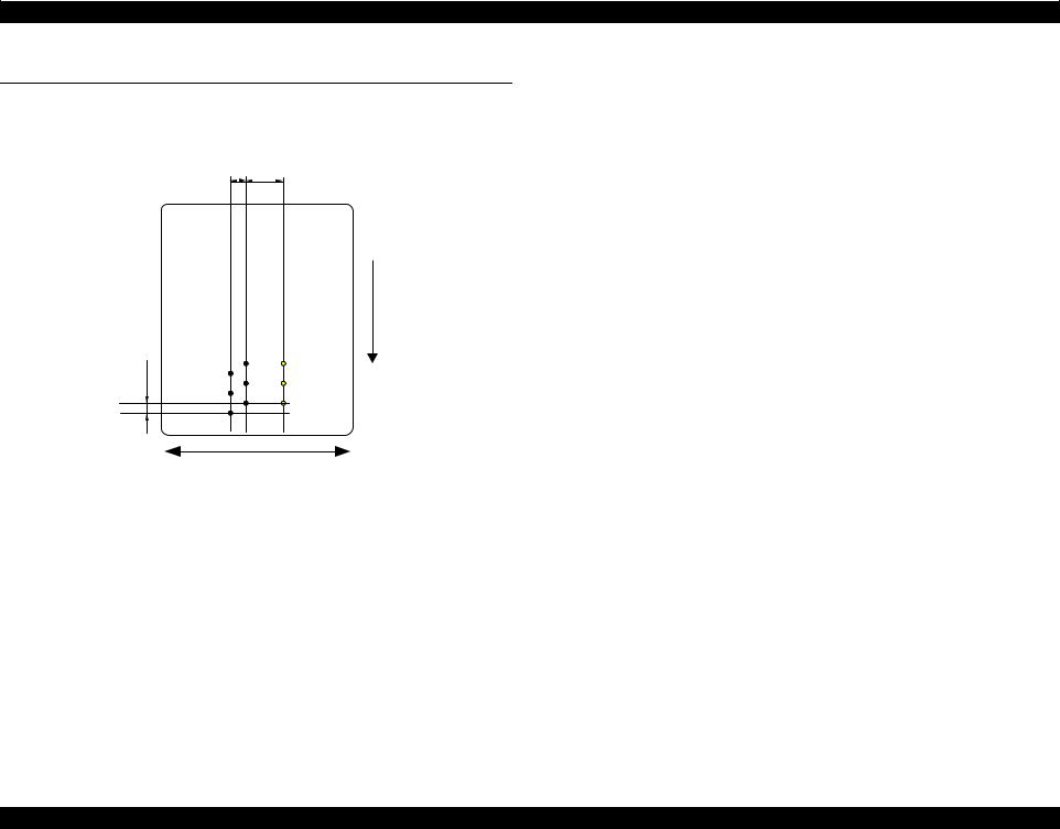
WorkForce 1100/Epson Stylus Office T1110/B1100/T1100/Epson ME Office 1100 |
Revision C |
2.3 Printhead Specifications
The Printhead of this product is a F-Mach head.
The following shows the arrangement of the nozzles and the color arrangement of each nozzle line when viewed the Print Head from behind.
2.258
(64/720inch)
A#180 
A#179 
A#178 
5.644
(160/720inch)
 B#180
B#180 C#180
C#180
 B#179
B#179 C#179
C#179
 B#178
B#178 C#178
C#178
0.071 (1/360inch) |
A column |
B column |
C column |
|
B#2 |
C#2 |
|
|
A#3 |
B#3 |
C#3 |
|
|
|
|
|
A#2 |
B#1 |
C#1 |
|
A#1 |
||
|
|
|
Carriage movement direction
Figure 2-2. Nozzle Arrangement
Paper feed direction
Table 2-2. Nozzle Lines and the Corresponding Ink Color
Ink |
Line |
|
Black |
A column: #1 to #180 |
|
B column: #1 to #180 |
||
|
||
Yellow |
C column*: #1 to C#60 |
|
|
|
|
Magenta |
C column*: #61 to C#120 |
|
|
|
|
Cyan |
C column*: #121 to C#180 |
|
|
|
Note "*": #1,#61 and #121 nozzles of C column are used only for flushing, and are not used for printing.
Operating Principles |
Printhead Specifications |
23 |
|
|
Confidential |

WorkForce 1100/Epson Stylus Office T1110/B1100/T1100/Epson ME Office 1100 |
Revision C |
2.4 PG Setting
As this printer uses an Auto PG (APG), an appropriate PG position is set according to the used paper type.
The following table indicates the PG positions, the main applications of each position, and the relationships between the two sensors used with the APG.
Table 2-3.
Application |
|
|
|
|
PG Position |
|
|
|
|
|
PG (– –) |
|
PG (–) |
|
PG (Typ) |
PG (+) |
|
PG (++) |
Release |
||
|
|
|
|
|||||||
Printing |
• Photo paper (A4 or more) |
• |
Photo paper |
• |
Plain paper |
• Envelope |
|
|
|
|
|
|
|
(Less than A4) |
• |
Exclusive paper |
• PG (Typ) rub avoidance |
|
– |
|
– |
|
|
|
|
• |
PG (-) rub avoidance |
|
|
|
|
|
|
|
|
|
|
|
|
|
|
|
|
Non-printing |
• Position for phase |
• |
PG adjustment position |
• |
Standby position after |
|
• |
Initialization at power-on |
• |
Paper jam removal |
|
alignment at reassembly |
|
|
|
power-on |
– |
• |
Cleaning (wiping) |
|
|
|
|
|
|
|
|
• |
Ink Cartridge |
|
|
|
|
|
|
|
|
|
|
|
|
||
|
|
|
|
|
|
|
|
replacement |
|
|
|
|
|
|
|
|
|
|
|
|
|
PG value |
1.0mm |
|
1.2mm |
|
1.7mm |
2.1mm |
|
4.5mm |
|
– |
|
|
|
|
|
|
|
|
|
|
|
Sensor |
PG (– –) |
PG (–) |
PG (Typ) |
PG (+) |
PG (++) |
Release |
APG Sensor 1* |
High |
High |
High |
High |
High |
High |
APG Sensor 2 |
Low |
Low |
Low |
Low |
High |
High |
Note "*": The signal output is “Low” while the PG positions are changed.
Operating Principles |
PG Setting |
24 |
|
|
Confidential |
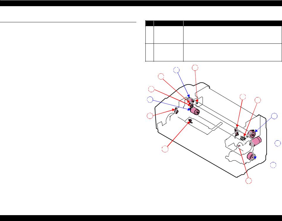
WorkForce 1100/Epson Stylus Office T1110/B1100/T1100/Epson ME Office 1100 |
Revision C |
2.5 Motors & Sensors
Motors
Table 2-4. List of Motors
Fig. |
Name |
|
Specific |
|
|
A |
PF Motor |
Type: DC Motor |
± 10% |
Drive voltage: 42 V DC ± 5% |
|
Armature resistance: 12.2 |
|
||||
|
|
|
|||
|
|
|
|
|
|
B |
APG Motor |
Type: DC Motor |
± 15% |
Drive voltage: 42 V DC ± 5% |
|
Armature resistance: 64.7 |
|
||||
|
|
|
|||
|
|
|
|
||
C |
ASF Motor |
Type: 4-phase 48-pole PM type stepping motor |
Drive voltage: 42 V DC ± 5% |
||
Winding resistance: 7.0 ± 10% (per phase at 25°C) |
|||||
|
|
||||
|
|
|
|
|
|
D |
CR Motor |
Type: DC Motor |
± 10% |
Drive voltage: 42 V DC ± 5% |
|
Armature resistance: 23.6 |
|
||||
|
|
|
|||
|
|
|
|
||
E |
Pump Motor |
Type: 4-phase 48-pole PM type stepping motor |
Drive voltage: 42 V DC ± 5% |
||
Winding resistance: 10.3 ± 10% (per phase at 25°C) |
|||||
|
|
||||
|
|
|
|
|
|
Sensors
Table 2-5. List of Sensors
Fig. |
Name |
Specific |
|
1 |
PF Encoder sensor |
Type: Rotary Encoder |
Drive voltage: 3.3 V DC ± 5% |
|
|
|
|
|
|
Type: Transmissive photo interrupter |
Drive voltage: 3.3 V DC ± 5% |
2 |
APG Sensor (1) |
Sensor output: |
|
• High: In the domain of each PG position |
|
||
|
|
|
|
|
|
• Low: Between PG positions |
|
|
|
|
|
|
|
Type: Transmissive photo interrupter |
Drive voltage: 3.3 V DC ± 5% |
3 |
APG Sensor (2) |
Sensor output: |
|
• High: In the domain of large PG |
|
||
|
|
|
|
|
|
• Low: In the domain of small PG |
|
|
|
|
|
|
|
Type: Transmissive photo interrupter |
Drive voltage: 3.3 V DC ± 5% |
4 |
ASF Sensor |
Sensor output: |
|
• High: Home position |
|
||
|
|
|
|
|
|
• Low: Other than home position |
|
|
|
|
|
|
|
Type: Transmissive photo interrupter |
Drive voltage: 3.3 V DC ± 5% |
5 |
PE Sensor |
Sensor output: |
|
• High (2.4 V or more): No paper |
|
||
|
|
|
|
|
|
• Low (0.4 V or less): Paper exists |
|
|
|
|
|
6 |
CR Encoder sensor |
Type: Linear Encoder |
Drive voltage: 3.3 V DC ± 5% |
Table 2-5. List of Sensors
Fig. |
Name |
|
Specific |
|
|
|
|
Type: Reflective photo interrupter |
Drive voltage: 3.3 V DC ± 5% |
||
7 |
PW Sensor |
Sensor output: |
|
|
|
• |
High: No paper |
|
|
||
|
|
|
|
||
|
|
• |
Low: Paper exists |
|
|
|
|
Type: Mechanical contact |
Drive voltage: 3.3 V DC ± 5% |
||
8 |
Cover Open |
Sensor output: |
|
|
|
Sensor |
• |
High: Cover closed |
|
|
|
|
|
|
|||
|
|
• |
Low: Cover open |
|
|
|
|
B |
4 |
|
|
|
|
|
|
|
|
|
3 |
|
|
|
|
2 |
|
|
|
|
|
A |
|
|
|
5 |
6 |
|
|
|
|
||
1 |
|
|
|
|
C |


 D 8
D 8


 E
E
7
Figure 2-3. Motors and Sensors Layout
Operating Principles |
Motors & Sensors |
25 |
Confidential
WorkForce 1100/Epson Stylus Office T1110/B1100/T1100/Epson ME Office 1100 |
Revision C |
2.6 Power-On Sequence
Table 2-6. Operation of the power-on sequence
This section describes the power-on sequences. |
|
|
|
|
|
|
|
|
|
|
|
|
|
|
|
Operation |
|
|
|
Movement of each |
Pump |
|||||||||||||||||||
|
|
|
|
|
|
|
|
|
|
|
|
|
|
|
|
|
|
component |
|
|
|
|
Motor*1 |
|||||||||||||||||
Condition |
|
|
|
|
|
|
|
|
|
|
|
1. |
Checking waste ink overflow |
130 |
|
|
|
|
HP |
|
|
|
0 |
|
|
|
|
|||||||||||||
|
|
|
|
|
|
|
|
|
|
|
|
|
|
|
|
|
|
|
|
|
||||||||||||||||||||
Completing ink charge. |
|
|
|
|
|
|
|
|
|
|
|
|
|
|
1-1. |
Reads out the protection counter value to check |
|
|
|
|
|
|
|
|
|
|
|
|
|
|
|
|
--- |
|||||||
No paper on the paper path. |
|
|
|
|
|
|
|
|
|
|
|
|
|
|
|
waste ink overflow. |
|
|
|
|
|
|
|
|
|
|
|
|
|
|
|
PG ++ |
|
|||||||
|
|
|
|
|
|
|
|
|
|
|
|
|
|
|
|
|
|
|
|
|
|
|
|
|
|
|
|
|||||||||||||
The Printhead is capped with the Cap of the Ink System. |
|
|
|
|
|
|
|
|
|
|
|
|
|
|
|
|
|
|
|
|
PG Typ. |
|
||||||||||||||||||
|
|
|
|
|
|
|
|
|
|
|
|
|
|
|
|
|
|
|
|
|
|
|||||||||||||||||||
|
|
|
|
|
|
|
|
|
|
|
|
|
|
|
|
|
|
|
|
|
|
|||||||||||||||||||
PG position is set to PG Typ. |
|
|
|
|
|
|
|
|
|
|
|
|
|
2. |
APG initialization |
130 |
|
|
|
|
HP |
|
|
|
0 |
|
|
|
||||||||||||
|
|
|
|
|
|
|
|
|
|
|
|
|
|
|
|
|
|
|
|
|
|
|
||||||||||||||||||
|
|
|
|
|
|
|
|
|
|
|
|
|
|
2-1. The APG Motor rotates counterclockwise until |
|
|
|
|
|
|
|
|
|
|
|
|
|
|
|
|
|
|||||||||
The Carriage is locked by the CR lock. |
|
|
|
|
|
|
|
|
|
|
|
|
|
|
|
|
|
|
|
|
|
|
|
|
|
|
|
|
|
|
--- |
|||||||||
|
|
|
|
|
|
|
|
|
|
|
|
|
|
|
the PG position is set to PG++ to initialize the |
|
|
|
|
|
|
|
|
|
|
|
|
|
|
|
|
|||||||||
|
|
|
|
|
|
|
|
|
|
|
|
|
|
|
|
|
|
|
|
|
|
|
|
|
|
|
|
|
|
|
||||||||||
|
|
|
|
|
|
|
|
|
|
|
|
|
|
|
|
|
|
|
|
|
|
|
APG mechanism. |
|
|
|
|
|
|
|
|
|
|
|
|
|
|
|
PG Typ. |
|
|
|
|
|
|
|
|
|
|
|
|
|
|
|
|
|
|
|
|
|
|
|
|
|
|
|
|
|
|
|
|
|
|
|
|
|
|
|
|
PG ++ |
|
|
|
|
|
|
|
|
|
|
|
|
|
|
|
|
|
|
|
|
|
|
|
|
|
|
|
|
|
|
|
|
|
|
|
|
|
|
|
|
|
|
CHECK |
|
The following explains how to use the simplified diagrams in Table |
|
|
3. |
Seeking the home position |
130 |
|
|
|
|
HP |
0 |
|
|
|
||||||||||||||||||||||||
POINT |
|
2-6. The diagrams show the movement of each component as seen |
|
|
|
3-1. The carriage moves to the 0-digit side slowly and |
|
|
|
|
|
|
|
|
|
|
|
|
|
|
|
|
--- |
|||||||||||||||||
|
|
|
|
|
|
|
|
|
|
|
|
|
|
|
|
|
|
|
|
|
||||||||||||||||||||
|
|
from the front of the printer. |
|
|
|
|
|
|
|
|
|
|
|
|
|
|
|
confirms it touches the Right Frame. |
|
|
|
|
|
|
|
|
|
|
|
|
|
|
|
PG ++ |
||||||
|
|
|
|
|
|
|
|
|
|
|
|
|
|
|
|
|
|
|
|
|
|
|
|
|
|
|
|
|
|
|
|
|||||||||
|
|
|
|
|
|
|
|
|
|
|
|
|
|
|
|
|
|
|
|
|
|
|
|
|
|
|
|
|
|
|
|
|
|
|
|
|
|
|
PG Typ. |
|
|
|
|
|
|
|
|
|
|
|
|
|
|
|
|
|
|
|
|
|
|
|
|
|
|
|
|
|
|
|
|
|
|
|
|
|
|
|
|
|
|
|
|
The rotation direction of the ASF |
PG variation by APG Motor drive |
|
|
|
|
3-2. |
The carriage moves to the 130-digit side slowly |
130 |
|
|
|
|
HP |
|
|
|
0 |
|
|
|
||||||||||||||||||
|
|
Motor |
PG becomes narrower (down-arrow): |
|
|
|
|
|
and confirms it touches the CR lock. |
|
|
|
|
|
|
|
|
|
|
|||||||||||||||||||||
|
|
Clockwise: |
|
Clockwise rotation |
|
|
|
|
|
|
|
|
|
|
|
|
|
|
|
|
|
|
|
|
|
--- |
||||||||||||||
|
|
|
|
|
|
|
|
|
|
|
|
|
|
|
|
|
|
|
|
|
|
|
|
|
||||||||||||||||
|
|
LD Roller rotates backward |
PG becomes wider (up-arrow): |
|
|
|
|
|
|
|
|
|
|
|
|
|
|
|
|
|
|
|
|
|
|
|||||||||||||||
|
|
|
|
|
|
|
|
|
|
|
|
|
|
|
|
|
|
|
|
|
|
|
|
|
||||||||||||||||
|
|
Counterclockwise: |
|
Counterclockwise rotation |
|
|
|
|
|
|
|
|
|
|
|
|
|
|
|
|
|
|
|
|
|
PG Typ. |
|
|||||||||||||
|
|
LD Roller rotates normally (Paper is fed) |
The following shows when PG is narrow. |
|
|
|
|
|
|
|
|
|
|
|
|
|
|
|
|
|
|
|
|
|
PG ++ |
|
||||||||||||||
|
|
|
|
|
|
|
|
|
|
|
|
|
|
|
|
|
|
|
|
|
|
|
|
|
||||||||||||||||
|
|
|
|
|
|
3-3. |
The carriage moves to the 0-digit side slowly and |
|
|
|
|
|
|
|
|
|
|
|
|
|
|
|
|
|
||||||||||||||||
|
|
The following shows clockwise rotation. |
|
|
|
|
|
|
|
|
|
|
|
|
|
|
130 |
|
|
|
|
HP |
|
|
|
0 |
|
|
|
|||||||||||
|
|
|
|
|
|
|
|
|
|
|
|
|
|
|
|
|
confirms it touches the Right Frame, and the |
|
|
|
|
|
|
|
|
|
||||||||||||||
|
|
|
|
|
|
|
|
|
|
|
|
|
|
|
|
|
|
|
|
|
|
|
|
|
|
|
|
|
|
|
|
|
|
|
|
|
|
|
|
|
|
|
|
|
|
|
|
|
|
|
|
|
|
|
|
|
|
|
|
|
|
|
|
|
|
|
|
|
|
|
|
|
|
|
|
|
|
|
|
|
|
|
|
|
|
Digit number of CR |
|
|
|
|
|
|
|
|
|
|
|
|
|
|
|
home position is fixed. |
|
|
|
|
|
|
|
|
|
|
|
|
|
|
|
|
--- |
|||
|
|
|
|
|
|
|
|
|
|
|
|
|
|
|
|
|
|
|
|
|
|
|
|
|
|
|
|
|
|
|
|
|
|
|
||||||
|
|
|
|
|
|
|
|
|
|
|
|
|
|
|
|
|
|
|
Afterward, the carriage position is monitored |
|
|
|
|
|
|
|
|
|
|
|
|
|
|
|
PG ++ |
|
||||
|
130 |
|
|
|
|
|
HP |
|
|
|
|
|
|
|
|
|
|
|
|
according to the signals from the CR Encoder. |
|
|
|
|
|
|
|
|
|
|
|
|
|
|
|
PG Typ. |
|
|||
|
|
|
|
|
|
|
|
|
|
|
|
|
|
|
|
|
|
|
|
|
|
|
|
|
|
|
|
|
|
|
|
|||||||||
|
|
|
|
|
|
|
|
|
|
|
|
|
|
|
|
|
|
|
|
|
|
|
|
|
|
|
|
|
|
|
||||||||||
|
|
|
|
|
|
|
|
|
|
|
|
|
|
|
|
position |
|
4. |
Releasing the CR lock |
130 |
|
|
|
|
HP |
|
|
0 |
|
|
|
|||||||||
|
|
|
|
|
|
|
|
|
|
|
|
|
|
|
|
|
|
|
|
|
|
|
|
|
|
|
||||||||||||||
|
|
|
|
|
LD Roller |
|
|
|
|
|
|
|
|
|
“PG Typ.” position. |
|
|
|
4-1. The Pump motor rotates counterclockwise and |
|
|
|
|
|
|
|
|
|
|
|
|
|
|
|
|
CCW |
||||
|
|
|
|
|
|
|
|
|
|
|
|
|
|
|
|
|
|
|
|
|
|
|
releases the CR lock. |
|
|
|
|
|
|
|
|
|
|
|
|
|
|
|
PG ++ |
|
|
|
|
|
|
|
|
|
|
|
|
|
|
|
|
|
|
|
|
|
|
|
|
|
|
|
|
|
|
|
|
|
|
|
|
|
|
|
|||
|
|
|
|
|
|
|
|
|
|
|
|
|
|
|
|
|
|
|
|
|
|
|
|
|
|
|
|
|
|
|
|
|
|
|
|
|
|
|
PG Typ. |
|
|
|
|
|
|
|
|
|
|
|
|
|
|
|
|
|
|
|
|
|
|
|
|
|
|
|
|
|
|
|
|
|
|
|
|
|
|
|
|
|
|
|
|
|
|
|
|
|
|
|
|
|
|
|
|
|
|
|
|
|
|
|
|
|
|
|
|
|
|
|
|
|
|
|
|
|
|
|
|
|
|
|
|
|
|
|
|
|
|
|
|
|
|
|
|
|
|
|
|
|
|
|
|
|
|
|
|
|
|
|
|
|
|
|
|
|
|
|
|
|
|
|
|
|
|
|
|
|
|
|
|
|
|
|
|
|
|
|
|
|
PG ++ |
|
|
|
4-2. |
The carriage slowly moves to the 130-digit side to |
130 |
|
|
|
|
HP |
|
|
|
0 |
|
|
|
|||||
|
|
|
|
|
|
|
|
|
|
|
|
|
|
|
|
|
|
|
|
|
|
|
|
|
|
|
|
|
|
|||||||||||
|
|
|
|
|
|
|
|
|
|
|
|
|
|
|
|
|
|
|
|
|
the CR lock check position. |
|
|
|
|
|
|
|
|
|
||||||||||
|
|
|
|
|
|
|
|
|
|
|
|
|
|
|
|
|
|
|
|
|
|
|
|
|
|
|
|
|
|
|
|
|
|
|
|
|
|
|||
|
|
|
|
|
|
|
|
|
|
|
|
|
|
|
|
|
|
|
|
|
|
|
|
|
|
|
|
|
|
|
|
|
|
|
|
|
|
|||
PG Typ. |
--- |
|
PG ++ |
PF Roller |
Carriage |
|
|
|
|
|
|
|
|
|
|
|
|
|
|
PG Typ. |
|
|
|
|
|
|
|
|
|
|
|
|
|
|
|
|
|||
|
4-3. The carriage slightly moves to the 130-digit side. |
|
|
|
|
|
|
|
|
|
|
||||||
|
|
|
|
|
|
|
|
|
|
|
|
|
|
||||
|
|
|
|
130 |
|
|
|
|
|
HP |
|
|
0 |
--- |
|||
|
|
|
|
|
|
|
|
|
|
|
|
|
|
|
|
||
The rotation direction of the PF Motor |
|
The condition of the CR lock |
|
|
|
|
|
|
|
|
|
|
|
|
|
||
Clockwise: |
|
Red: CR lock is set |
|
|
|
|
|
|
|
|
|
|
|
|
|
|
PG ++ |
Paper is fed normally |
|
White:CR lock is released |
|
|
|
|
|
|
|
|
|
|
|
|
|
|
PG Typ. |
Counterclockwise: |
|
The above shows the CR lock is set. |
|
|
|
|
|
|
|
|
(Continue to the next page) |
||||||
Paper is fed backward |
|
|
|
|
|
|
|
|
|
|
|||||||
|
|
|
|
|
|
|
|
|
|
|
|
|
|
|
|
|
|
The above shows clockwise rotation. |
|
|
|
|
|
|
|
|
|
|
|
|
|
|
|
|
|
|
|
|
|
|
|
|
|
|
|
|
|
|
|
|
|
|
|
Figure 2-4. Carriage Movement |
|
|
|
|
|
|
|
|
|
|
|
|
|
|
|
||
Operating Principles Power-On Sequence 26
Confidential
WorkForce 1100/Epson Stylus Office T1110/B1100/T1100/Epson ME Office 1100 |
Revision C |
Table 2-6. Operation of the power-on sequence
|
Operation |
|
|
|
Movement of each |
Pump |
||||||||||||||
|
|
|
|
|
|
component |
|
|
|
|
Motor*1 |
|||||||||
|
|
|
|
|
|
|
|
|
|
|
||||||||||
|
4-4. The Pump Motor rotates counterclockwise to set |
130 |
|
|
|
|
|
|
|
HP |
|
|
0 |
|
|
|
|
|||
|
the Wiper of the Ink System, and then the Pump |
|
|
|
|
|
|
|
|
|
|
|
|
CCW |
||||||
|
|
|
|
|
|
|
|
|
|
|
|
|
|
|
|
|
|
|
||
|
Motor rotates clockwise to retract the Wiper. |
|
|
|
|
|
|
|
|
|
|
|
|
|
|
|
|
|
PG ++ |
CW |
|
|
|
|
|
|
|
|
|
|
|
|
|
|
|
|
|
|
|
||
|
|
|
|
|
|
|
|
|
|
|
|
|
|
|
|
|
|
|
PG Typ. |
|
|
|
|
|
|
|
|
|
|
|
|
|
|
|
|
|
|
|
|
|
|
|
4-5. The carriage slowly returns to its home position. |
130 |
|
|
|
|
|
|
|
HP |
|
|
0 |
|
|
|
|
|||
|
|
|
|
|
|
|
|
|
|
|
|
|
PG ++ |
--- |
||||||
|
|
|
|
|
|
|
|
|
|
|
|
|
|
|
|
|
|
|
||
|
|
|
|
|
|
|
|
|
|
|
|
|
|
|
|
|
|
|
||
|
|
|
|
|
|
|
|
|
|
|
|
|
|
|
|
|
|
|
||
|
|
|
|
|
|
|
|
|
|
|
|
|
|
|
|
|
|
|
|
|
|
|
|
|
|
|
|
|
|
|
|
|
|
|
|
|
|
|
|
PG Typ. |
|
|
|
|
|
|
|
|
|
|
|
|
|
|
|
|
|
|
|
|
|
|
|
|
|
|
|
|
|
|
|
|
|
|
|
|
|
|
|
|
|
|
|
5. |
Setting the APG to PG Typ. |
130 |
|
|
|
|
|
|
|
HP |
|
|
0 |
|
|
|
|
|||
|
|
|
|
|
|
|
|
|
|
|
|
|
||||||||
|
5-1. The APG Motor rotates clockwise and sets to PG |
|
|
|
|
|
|
|
|
|
|
|
|
|
|
|
|
|
|
--- |
|
Typ. |
|
|
|
|
|
|
|
|
|
|
|
|
|
|
|
|
|
PG ++ |
|
|
|
|
|
|
|
|
|
|
|
|
|
|
|
|
|
|
|
|
|
|
|
|
|
|
|
|
|
|
|
|
|
|
|
|
|
|
|
|
|
|
|
|
|
|
|
|
|
|
|
|
|
|
|
|
|
|
|
|
|
|
|
|
|
|
|
|
|
|
|
|
|
|
|
|
|
|
|
|
|
|
|
PG Typ. |
|
|
|
|
|
|
|
|
|
|
|
|
|
|
|
|
|
|
|
|
|
|
6. PF-ASF initialization |
130 |
|
|
|
|
|
|
|
HP |
|
|
|
0 |
|
|
|
|
|||
|
6-1. The PE Sensor detects no paper and the ASF |
|
|
|
|
|
|
|
|
|
|
|
|
|
|
|
|
|
|
--- |
|
Sensor detects that the ASF is on its home |
|
|
|
|
|
|
|
|
|
|
|
|
|
|
|
|
|
|
|
|
position, and then the PF Motor rotates clockwise |
|
|
|
|
|
|
|
|
|
|
|
|
|
|
|
|
|
PG ++ |
|
|
|
|
|
|
|
|
|
|
|
|
|
|
|
|
|
|
|
|
||
|
for approx. one second. |
|
|
|
|
|
|
|
|
|
|
|
|
|
|
|
|
|
PG Typ. |
|
|
|
|
|
|
|
|
|
|
|
|
|
|
|
|
|
|
|
|
|
|
|
|
|
|
|
|
|
|
|
|
|
|
|
|
|
|
|
|
|
|
|
|
6-2. While monitoring the ASF Sensor, the ASF |
130 |
|
|
|
|
|
|
|
HP |
|
|
|
0 |
|
|
|
|
||
|
Motor slowly rotates counterclockwise until the |
|
|
|
|
|
|
|
|
|
|
|
|
|
||||||
|
|
|
|
|
|
|
|
|
|
|
|
|
|
|
|
|
|
|
|
|
|
ASF gets out of its home position. |
|
|
|
|
|
|
|
|
|
|
|
|
|
|
|
|
|
PG ++ |
--- |
|
|
|
|
|
|
|
|
|
|
|
|
|
|
|
|
|
|
|||
|
|
|
|
|
|
|
|
|
|
|
|
|
|
|
|
|
|
|
|
|
|
|
|
|
|
|
|
|
|
|
|
|
|
|
|
|
|
|
|
|
|
|
|
|
|
|
|
|
|
|
|
|
|
|
|
|
|
|
|
|
PG Typ. |
|
|
|
|
|
|
|
|
|
|
|
|
|
|
|
|
|
|
|
|
|
|
|
6-3. The ASF Motor rotates clockwise and the ASF |
130 |
|
|
|
|
|
|
|
HP |
|
|
|
0 |
|
|
|
|
||
|
Sensor detects that the ASF is on its home |
|
|
|
|
|
|
|
|
|
|
|
|
|
||||||
|
|
|
|
|
|
|
|
|
|
|
|
|
|
|
|
|
|
|
|
|
|
position. |
|
|
|
|
|
|
|
|
|
|
|
|
|
|
|
|
|
PG ++ |
--- |
|
|
|
|
|
|
|
|
|
|
|
|
|
|
|
|
|
|
|
|
|
|
|
|
|
|
|
|
|
|
|
|
|
|
|
|
|
|
|
|
|
|
|
|
|
|
|
|
|
|
|
|
|
|
|
|
|
|
|
|
|
PG Typ. |
|
|
|
|
|
|
|
|
|
|
|
|
|
|
|
|
|
|
|
|
|
|
|
|
|
|
|
|
|
|
|
|
|
|
|
|
|
|
|
|
|
|
|
7. |
Low temperature operation sequence*2 |
130 |
|
|
|
|
|
|
|
HP |
|
|
0 |
|
|
|
|
|||
|
|
|
|
|
|
|
|
|
|
|
|
|
||||||||
|
7-1. The carriage moves back and forth between 0- |
|
|
|
|
|
|
|
|
|
|
|
|
|
|
|
|
|
|
--- |
|
|
|
|
|
|
|
|
|
|
|
|
|
|
|
|
|
|
|
||
|
digit side and the 130-digit side for two times. |
|
|
|
|
|
|
|
|
|
|
|
|
|
|
|
|
|
PG ++ |
|
|
|
|
|
|
|
|
|
|
|
|
|
|
|
|
|
|
|
|||
|
|
|
|
|
|
|
|
|
|
|
|
|
|
|
|
|
|
|
|
|
|
|
|
|
|
|
|
|
|
|
|
|
|
|
|
|
|
|
|
|
|
|
|
|
|
|
|
|
|
|
|
|
|
|
|
|
|
|
|
|
PG Typ. |
|
|
|
|
|
|
|
|
|
|
|
|
|
|
|
|
|
|
|
|
|
|
8. |
CR Motor measurement |
130 |
|
|
|
|
|
|
|
HP |
|
|
|
0 |
|
|
|
|
||
|
|
|
|
|
|
|
|
|
|
|
|
|
|
|||||||
8-1. The carriage slowly moves to the 130-digit side.
---
PG ++
PG Typ.
Table 2-6. Operation of the power-on sequence
Operation |
|
|
|
Movement of each |
Pump |
||||||||||||||
|
|
|
|
|
component |
|
|
|
Motor*1 |
||||||||||
|
|
|
|
|
|
|
|
|
|||||||||||
8-2. The carriage performs a load measurement while |
130 |
|
|
|
|
|
|
HP |
|
|
|
|
0 |
|
|
|
|||
moving to the VH Check position, and records the |
|
|
|
|
|
|
|
|
|
|
|
|
|
||||||
detected voltage of the PW sensor at the specified |
|
|
|
|
|
|
|
|
|
|
|
|
|
|
|
|
|
|
--- |
|
|
|
|
|
|
|
|
|
|
|
|
|
|
|
|
|
|
||
three positions, then stops. |
|
|
|
|
|
|
|
|
|
|
|
|
|
|
|
|
|
PG ++ |
|
|
|
|
|
|
|
|
|
|
|
|
|
|
|
|
|
|
|
||
|
|
|
|
|
|
|
|
|
|
|
|
|
|
|
|
|
|
|
|
|
|
|
|
|
|
|
|
|
|
|
|
|
|
|
|
|
|
PG Typ. |
|
|
|
|
|
|
|
|
|
|
|
|
|
|
|
|
|
|
|
|
|
|
|
|
|
|
|
|
|
|
|
|
|
|
|
|
|
|
|
|
|
8-3. The carriage detects the voltage of the PW sensor |
130 |
|
|
|
|
|
|
HP |
|
|
|
|
0 |
|
|
|
|||
at the carriage stop position (the black area at the |
|
|
|
|
|
|
|
|
|
|
|
|
|
|
|
|
|
|
|
Paper Guide Front). |
|
|
|
|
|
|
|
|
|
|
|
|
|
|
|
|
|
PG ++ |
--- |
|
|
|
|
|
|
|
|
|
|
|
|
|
|
|
|
|
|
|
|
|
|
|
|
|
|
|
|
|
|
|
|
|
|
|
|
|
|
PG Typ. |
|
|
|
|
|
|
|
|
|
|
|
|
|
|
|
|
|
|
|
|
|
|
|
|
|
|
|
|
|
|
|
|
|
|
|
|
|
|
|
|
|
8-4. The carriage performs a load measurement while |
130 |
|
|
|
|
|
|
HP |
|
|
|
|
0 |
|
|
|
|||
moving to the 0-digit side, and stops. |
|
|
|
|
|
|
|
|
|
|
|
|
|||||||
|
|
|
|
|
|
|
|
|
|
|
|
|
|
|
|
|
|
|
|
|
|
|
|
|
|
|
|
|
|
|
|
|
|
|
|
|
|
PG ++ |
--- |
|
|
|
|
|
|
|
|
|
|
|
|
|
|
|
|
|
|
|
|
|
|
|
|
|
|
|
|
|
|
|
|
|
|
|
|
|
|
|
|
|
|
|
|
|
|
|
|
|
|
|
|
|
|
|
|
|
|
PG Typ. |
|
|
|
|
|
|
|
|
|
|
|
|
|
|
|
|
|
|
|
|
|
9. PF Motor measurement |
130 |
|
|
|
|
|
|
HP |
|
|
|
0 |
|
|
|
||||
|
|
|
|
|
|
|
|
|
|
|
|
||||||||
9-1. The PF motor rotates clockwise for approx. two |
|
|
|
|
|
|
|
|
|
|
|
|
|
|
|
|
|
|
--- |
seconds, and performs a load measurement. |
|
|
|
|
|
|
|
|
|
|
|
|
|
|
|
|
|
PG ++ |
|
|
|
|
|
|
|
|
|
|
|
|
|
|
|
|
|
|
|
|
|
|
|
|
|
|
|
|
|
|
|
|
|
|
|
|
|
|
|
PG Typ. |
|
|
|
|
|
|
|
|
|
|
|
|
|
|
|
|
|
|
|
|
|
9-2. The carriage returns to its home position. |
130 |
|
|
|
|
|
|
HP |
|
|
|
|
0 |
|
|
|
|||
|
|
|
|
|
|
|
|
|
|
|
|
|
|
|
|
|
|
PG ++ |
--- |
|
|
|
|
|
|
|
|
|
|
|
|
|
|
|
|
|
|
||
|
|
|
|
|
|
|
|
|
|
|
|
|
|
|
|
|
|
|
|
|
|
|
|
|
|
|
|
|
|
|
|
|
|
|
|
|
|
|
|
|
|
|
|
|
|
|
|
|
|
|
|
|
|
|
|
|
|
PG Typ. |
|
|
|
|
|
|
|
|
|
|
|
|
|
|
|
|
|
|
|
|
|
10. Detecting ink cartridge and initializing ink |
130 |
|
|
|
|
|
|
HP |
|
|
|
|
0 |
|
|
|
|||
system*3 |
|
|
|
|
|
|
|
|
|
|
|
||||||||
|
|
|
|
|
|
|
|
|
|
|
|
|
|
|
|
|
|
|
|
10-1. The carriage moves to the 130-digit side to check |
|
|
|
|
|
|
|
|
|
|
|
|
|
|
|
|
|
|
--- |
the ink end sensor. The ink remaining is detected |
|
|
|
|
|
|
|
|
|
|
|
|
|
|
|
|
|
PG ++ |
|
|
|
|
|
|
|
|
|
|
|
|
|
|
|
|
|
|
|
||
after completing the check. |
|
|
|
|
|
|
|
|
|
|
|
|
|
|
|
|
|
PG Typ. |
|
|
|
|
|
|
|
|
|
|
|
|
|
|
|
|
|
|
|
|
|
|
|
|
|
|
|
|
|
|
|
|
|
|
|
|
|
|
|
|
|
10-2. The carriage slowly returns to its home position. |
130 |
|
|
|
|
|
|
HP |
|
|
|
|
0 |
|
|
|
|||
|
|
|
|
|
|
|
|
|
|
PG ++ |
--- |
||||||||
|
|
|
|
|
|
|
|
|
|
|
|
|
|
|
|
|
|
||
|
|
|
|
|
|
|
|
|
|
|
|
|
|
|
|
|
|
||
|
|
|
|
|
|
|
|
|
|
|
|
|
|
|
|
|
|
|
|
|
|
|
|
|
|
|
|
|
|
|
|
|
|
|
|
|
|
|
|
|
|
|
|
|
|
|
|
|
|
|
|
|
|
|
|
|
|
PG Typ. |
|
|
|
|
|
|
|
|
|
|
|
|
|
|
|
|
|
|
|
|
|
|
|
|
|
|
|
|
|
|
|
|
|
|
|
|
|
|
|
|
|
11. CR lock setting |
130 |
|
|
|
|
|
|
HP |
|
|
|
|
0 |
|
|
|
|||
11-1. The Pump Motor rotates clockwise, and sets |
|
|
|
|
|
|
|
|
|
|
|
|
|
|
|
|
|
|
CW |
the CR lock.*3 |
|
|
|
|
|
|
|
|
|
|
|
|
|
|
|
|
|
PG ++ |
|
|
|
|
|
|
|
|
|
|
|
|
|
|
|
|
|
|
|
|
|
|
|
|
|
|
|
|
|
|
|
|
|
|
|
|
|
|
|
PG Typ. |
|
|
|
|
|
|
|
|
|
|
|
|
|
|
|
|
|
|
|
|
|
|
|
|
|
|
|
|
|
|
|
|
|
|
|
|
|
|
|
|
|
|
|
|
|
|
|
|
|
|
|
|
|
|
|
|
|
|
|
|
|
|
|
|
|
|
|
|
|
|
(Continue to the next page) |
||||||||||
Operating Principles |
Power-On Sequence |
27 |
Confidential
WorkForce 1100/Epson Stylus Office T1110/B1100/T1100/Epson ME Office 1100 |
Revision C |
Table 2-6. Operation of the power-on sequence
Operation
11-2. The carriage moves to the 130-digit side slowly and confirms it touches the CR lock.
11-3. The carriage returns to its home position.
|
|
|
Movement of each |
Pump |
|||||||||||||
|
|
|
component |
|
|
|
|
|
Motor*1 |
||||||||
130 |
|
|
|
HP |
|
|
|
|
0 |
|
|
PG ++ |
--- |
||||
|
|
|
|
|
|
|
|
|
|||||||||
|
|
|
|
|
|
|
|
|
|
|
|
|
|
|
|
||
|
|
|
|
|
|
|
|
|
|
|
|
|
|
|
|
||
|
|
|
|
|
|
|
|
|
|
|
|
|
|
|
|
|
|
|
|
|
|
|
|
|
|
|
|
|
|
|
|||||
|
|
|
|
|
|
|
|
|
|
|
|
|
|
|
|
PG Typ. |
|
130 |
|
|
|
HP |
|
|
|
|
0 |
|
|
PG ++ |
--- |
||||
|
|
|
|
|
|
|
|||||||||||
|
|
|
|
|
|
|
|||||||||||
|
|
|
|
|
|
|
|
|
|
|
|
|
|
|
|
||
|
|
|
|
|
|
|
|
|
|
|
|
|
|
|
|
||
|
|
|
|
|
|
|
|
|
|
|
|
|
|
|
|
|
|
|
|
|
|
|
|
|
|
|
|
|
|
|
|
|
|
||
|
|
|
|
|
|
|
|
|
|
|
|
|
|
|
|
PG Typ. |
|
|
|
|
|
|
|
|
|
|
|
|
|
|
|
|
|
|
|
|
|
|
|
|
|
|
|
|
|
|
|
|
|
|
|
|
|
Note "*1": The rotation directions of the Pump Motor and their corresponding functions are as follows.
Clockwise: Cap closing/Pump suction/Wiper retracting/CR locking Counterclockwise: Cap opening/Pump release/Wiper setting/CR unlocking
"*2": Executes when the detected temperature is under 5 oC (41oF) by the thermistor on the Printhead.
"*3": The empty suction operation may occur depending on the situation.
2.7 Printer Initialization
There are four kinds of initialization method, and the following explains each initialization
1.Hardware initialization
This printer is initialized when turning the printer power on, or printer recognized the cold-reset command (remote RS command).
When printer is initialized, the following actions are performed.
(a)Initializes printer mechanism
(b)Clears input data buffer
(c)Clears print buffer
(d)Sets default values
2.Operator initialization
Initialization when resetting the USB software, and the following are performed.
(a)Clears input data buffer
(b)Clears print buffer
(c)Sets default values
3.Software initialization
The ESC@ command also initialize the printer.
When printer is initialized, the following actions are performed.
(a)Clears print buffer
(b)Sets default values
4.IEEE 1284.4 “rs” command initialization
The printer recognized the IEEE 1284.4 “rs” command. When printer is initialized, the following action is performed. Initialization when an error occurs.
(a)Initializes printer mechanism
(b)Clears input data buffer
(c)Clears print buffer
(d)Sets default values
Initialization in normal operation
(a)Clears input data buffer
(b)Clears print buffer
(c)Sets default values
Operating Principles |
Printer Initialization |
28 |
Confidential

C H A P T E R
3
TROUBLESHOOTING
Confidential

WorkForce 1100/Epson Stylus Office T1110/B1100/T1100/Epson ME Office 1100 |
Revision C |
3.1 Overview
This chapter describes unit-level troubleshooting.
3.1.1 Troubleshooting according to Error Messages
After checking the printer LED and STM3 error indications, you can grasp the fault location using the check list in this section. When you find the fault location, refer to Chapter 4 “Disassembly and Reassembly” and change the corresponding part and/or unit. The following table indicates the check point reference tables corresponding to the error states (LED and STM3).
Table 3-1. List of Error Messages
Error Status |
|
LED Indications |
|
STM3 Message |
See the table for Troubleshooting |
||
Power |
|
Paper |
Ink |
||||
|
|
|
|
||||
|
|
|
|
|
|
Communication error |
|
Communication error |
- |
|
- |
|
- |
Check all connections and make sure all devices are on. If the power was |
|
|
|
turned off during printing, cancel the print job. If the error does not clear, |
|
||||
|
|
|
|
|
|
Refer to Table 3-2 ?Troubleshooting of Communication |
|
|
|
|
|
|
|
see your printer documentation. |
|
|
|
|
|
|
|
Error? (P.32) |
|
Model Difference |
|
|
|
|
|
Different device from specified |
|
|
|
|
|
|
|
||
- |
|
- |
|
- |
Attempting to connect to a different device from that specified in the driver. |
|
|
|
|
|
|
|
|
Check the driver settings and the device. |
|
Printer cover open |
- |
|
Flash |
|
- |
Printer cover open |
Refer to Table 3-3 ?Troubleshooting of Printer Cover |
error |
|
|
Close the printer cover. |
Open Error? (P.34) |
|||
|
|
|
|
|
|||
|
|
|
|
|
|
Paper out or not loaded correctly |
Refer to Table 3-4 ?Troubleshooting of Paper Out |
Paper out error |
- |
|
Light |
|
- |
Reload the paper, then press the Paper button on the printer or click the |
|
|
|
[Continue] button if it appears on the screen. To cancel the print job, click |
Error? (P.35) |
||||
|
|
|
|
|
|
||
|
|
|
|
|
|
the [Cancel] button if it appears on the screen. |
|
Paper jam error |
|
|
|
|
|
Paper jam |
Refer to Table 3-5 ?Troubleshooting of Paper Jam |
- |
|
Flash |
|
- |
Press the Paper button on the printer or click the [Eject] button when it |
||
|
|
Error? (P.37) |
|||||
|
|
|
|
|
|
appears on the screen. Remove any remaining jammed paper by hand. |
|
|
|
|
|
|
|
|
|
|
|
|
|
|
|
|
|
|
|
|
|
|
|
Page not printed or multi-page error |
Refer to Table 3-6 ?Troubleshooting of Multi-feed |
Multi-feed error |
- |
|
Light |
|
- |
A page has not been printed, multiple pages have been fed into the printer at |
|
|
|
once, or the wrong paper size has been fed into the printer. Remove and |
error? (P.38) |
||||
|
|
|
|
|
|
||
|
|
|
|
|
|
reload the paper. Press the Paper button if necessary. |
|
|
|
|
|
|
|
|
|
Troubleshooting |
Overview |
30 |
Confidential
Loading...