


Stylus Pro 9600
Table of contents
 Loading...
®
SERVICE MANUAL
Color Large Format Inkjet Printer
EPSON Stylus Pro 7600/9600
SEIJ01017

Notice:
All rights reserved. No part of this manual may be reproduced, stored in a retrieval system, or transmitted in any form or by any means, electronic,
mechanical, photocopying, recording, or otherwise, without the prior written permission of SEIKO EPSON CORPORATION.
The contents of this manual are subject to change without notice.
All effort have been made to ensure the accuracy of the contents of this manual. However, should any errors be detected, SEIKO EPSON would greatly
appreciate being informed of them.
The above not withstanding SEIKO EPSON CORPORATION can assume no responsibility for any errors in this manual or the consequences thereof.
EPSON is a registered trademark of SEIKO EPSON CORPORATION.
General Notice: Other product names used herein are for identification purpose only and may be trademarks or registered trademarks of their
respective owners. EPSON disclaims any and all rights in those marks.
Copyright © 2002 SEIKO EPSON CORPORATION.
Imaging & Information Product Division
TPCS Quality Assurance Department

PRECAUTIONS
Precautionary notations throughout the text are categorized relative to 1)Personal injury and 2) damage to equipment.
DANGER Signals a precaution which, if ignored, could result in serious or fatal personal injury. Great caution should be exercised in
performing procedures preceded by DANGER Headings.
WARNING Signals a precaution which, if ignored, could result in damage to equipment.
The precautionary measures itemized below should always be observed when performing repair/maintenance procedures.
DANGER
1. ALWAYS DISCONNECT THE PRODUCT FROM THE POWER SOURCE AND PERIPHERAL DEVICES PERFORMING ANY MAINTENANCE
OR REPAIR PROCEDURES.
2. NO WORK SHOULD BE PERFORMED ON THE UNIT BY PERSONS UNFAMILIAR WITH BASIC SAFETY MEASURES AS DICTATED FOR
ALL ELECTRONICS TECHNICIANS IN THEIR LINE OF WORK.
3. WHEN PERFORMING TESTING AS DICTATED WITHIN THIS MANUAL, DO NOT CONNECT THE UNIT TO A POWER SOURCE UNTIL
INSTRUCTED TO DO SO. WHEN THE POWER SUPPLY CABLE MUST BE CONNECTED, USE EXTREME CAUTION IN WORKING ON
POWER SUPPLY AND OTHER ELECTRONIC COMPONENTS.
WARNING
1. REPAIRS ON EPSON PRODUCT SHOULD BE PERFORMED ONLY BY AN EPSON CERTIFIED REPAIR TECHNICIAN.
2. MAKE CERTAIN THAT THE SOURCE VOLTAGES IS THE SAME AS THE RATED VOLTAGE, LISTED ON THE SERIAL NUMBER/RATING
PLATE. IF THE EPSON PRODUCT HAS A PRIMARY AC RATING DIFFERENT FROM AVAILABLE POWER SOURCE, DO NOT CONNECT IT
TO THE POWER SOURCE.
3. ALWAYS VERIFY THAT THE EPSON PRODUCT HAS BEEN DISCONNECTED FROM THE POWER SOURCE BEFORE REMOVING OR
REPLACING PRINTED CIRCUIT BOARDS AND/OR INDIVIDUAL CHIPS.
4. IN ORDER TO PROTECT SENSITIVE MICROPROCESSORS AND CIRCUITRY, USE STATIC DISCHARGE EQUIPMENT, SUCH AS ANTISTATIC WRIST STRAPS, WHEN ACCESSING INTERNAL COMPONENTS.
5. REPLACE MALFUNCTIONING COMPONENTS ONLY WITH THOSE COMPONENTS BY THE MANUFACTURE; INTRODUCTION OF
SECOND-SOURCE ICs OR OTHER NON-APPROVED COMPONENTS MAY DAMAGE THE PRODUCT AND VOID ANY APPLICABLE EPSON
WARRANTY.
About This Manual
This manual describes basic functions, theory of electrical and mechanical operations, maintenance and repair procedures of the printer. The instructions and procedures included
herein are intended for the experienced repair technicians, and attention should be given to the precautions on the preceding page.
Manual Configuration
This manual consists of six chapters and Appendix.
CHAPTER 1.PRODUCT DESCRIPTIONS
Provides a general overview and specifications of the product.
CHAPTER 2.OPERATING PRINCIPLES
Describes the theory of electrical and mechanical operations of
the product.
CHAPTER 3.TROUBLESHOOTING
Describes the step-by-step procedures for the troubleshooting.
CHAPTER 4.DISASSEMBLY / ASSEMBLY
Describes the step-by-step procedures for disassembling and
assembling the product.
CHAPTER 5.ADJUSTMENT
Provides Epson-approved methods for adjustment.
CHAPTER 6.MAINTENANCE
Provides preventive maintenance procedures and the lists of
Epson-approved lubricants and adhesives required for servicing
the product.
APPENDIX Provides the following additional information for reference:
• Connector pin assignments
• Electric circuit boards components layout
• Electrical circuit boards schematics
• Exploded diagram & Parts List
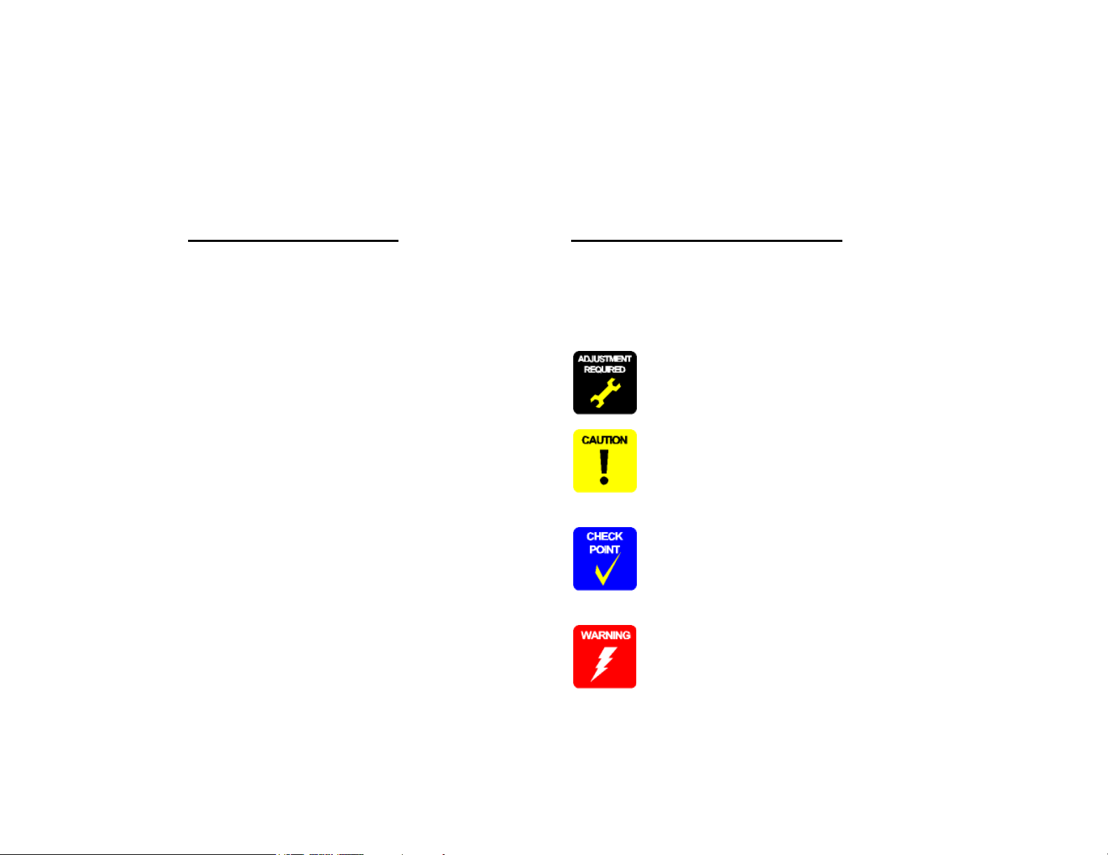
Symbols Used in this Manual
Various symbols are used throughout this manual either to provide additional
information on a specific topic or to warn of possible danger present during a
procedure or an action. Be aware of all symbols when they are used, and
always read NOTE, CAUTION, or WARNING messages.
Indicates an operating or maintenance procedure, practice or
condition that is necessary to keep the product’s quality.
Indicates an operating or maintenance procedure, practice, or
condition that, if not strictly observed, could result in damage to,
or destruction of, equipment.
May indicate an operating or maintenance procedure, practice or
condition that is necessary to accomplish a task efficiently. It may
also provide additional information that is related to a specific
subject, or comment on the results achieved through a previous
action.
Indicates an operating or maintenance procedure, practice or
condition that, if not strictly observed, could result in injury or loss
of life.

Revision Status
Revision Date of Issue Description
A May 10, 2002 First release

EPSON Stylus Pro 7600/9600 Revision A
Contents
Chapter 1 Product Description
1.1 Product Description ............................................................................................ 12
1.1.1 Features ...................................................................................................... 12
1.1.2 Differences between Stylus Pro 7600 and Stylus Pro 9600 ...................... 13
1.2 Basic Specifications ............................................................................................ 14
1.2.1 Print Specifications .................................................................................... 14
1.2.2 Character Specification .............................................................................. 14
1.2.3 Control Code .............................................................................................. 14
1.2.4 Paper Feed ................................................................................................. 14
1.2.5 Paper Specifications ................................................................................... 15
1.2.5.1 Roll Paper ........................................................................................... 15
1.2.5.2 Sheet ................................................................................................... 16
1.2.5.3 Special Paper ...................................................................................... 18
1.2.6 Mechanism Specifications ......................................................................... 21
1.2.6.1 Printable Area ..................................................................................... 21
1.2.6.2 Paper Set Lever .................................................................................. 22
1.2.6.3 Cutting Specification .......................................................................... 22
1.2.6.4 Acoustic Noise ................................................................................... 23
1.2.7 Electrical Specifications (TBD) ................................................................. 23
1.2.8 Reliability .................................................................................................. 23
1.2.8.1 Total Print Volume ............................................................................. 23
1.2.8.2 Print Head Life ................................................................................... 23
1.2.8.3 Maintenance Tank Life ...................................................................... 23
1.2.8.4 Cutter Life average ............................................................................. 23
1.2.8.5 Maintenance Parts (TBD) ................................................................... 23
1.2.9 Ambient Conditions ................................................................................... 24
1.2.9.1 Temperature/Humidity ....................................................................... 24
1.2.9.2 Vibration ............................................................................................. 24
1.2.9.3 Shock .................................................................................................. 24
1.2.9.4 Surrounding Space ............................................................................. 25
1.2.10 Overall Dimensions ................................................................................. 26
1.2.11 Accessories .............................................................................................. 28
1.2.11.1 Accessories and Options for Stylus Pro 7600 .................................. 28
1.2.11.2 Accessories and Options for Stylus Pro 9600 .................................. 29
1.3 External View and Parts Names ......................................................................... 30
1.4 Operating Panel .................................................................................................. 31
1.4.1 Buttons and Functions ............................................................................... 31
1.4.1.1 Functions of Buttons .......................................................................... 31
1.4.1.2 LEDs ................................................................................................... 32
1.4.2 Indications on the Panel ............................................................................. 33
1.4.2.1 lED Indications in Normal Mode ....................................................... 33
1.4.2.2 LCD Indications in Normal Mode ..................................................... 34
1.4.3 SelecType .................................................................................................. 35
1.4.3.1 Outline ................................................................................................ 35
1.4.3.2 Panel Setting Menu Item .................................................................... 36
1.4.3.3 PG Setting .......................................................................................... 40
1.4.3.4 Page Lines .......................................................................................... 41
1.4.3.5 Interface Select ................................................................................... 41
1.4.3.6 Code Page Switching ......................................................................... 41
1.4.3.7 Roll Paper Margin .............................................................................. 41
1.4.3.8 Detect Paper Width ............................................................................ 42
1.4.3.9 Detect Skew Error .............................................................................. 42
1.4.3.10 Job Timeout Setting ......................................................................... 42
1.4.3.11 No margin print setting .................................................................... 43
1.4.3.12 Cutter position adjustment ............................................................... 44
1.4.3.13 Auto margin refresh ......................................................................... 44
1.4.3.14 Panel Setup Value Initialization ....................................................... 45
1.4.3.15 Nozzle Check Pattern Printing ......................................................... 45
1.4.3.16 Status Printing .................................................................................. 46
1.4.3.17 Job Information Print ....................................................................... 48
1.4.3.18 Firmware version .............................................................................. 49
1.4.3.19 Printable pages of each ink cartridge ............................................... 49
1.4.3.20 Ink remaining ................................................................................... 49
1.4.3.21 Maintenance tank count ................................................................... 49
1.4.3.22 Use counter ....................................................................................... 50
1.4.3.23 Clear use counter .............................................................................. 50
1.4.3.24 Job history display ............................................................................ 50
6

EPSON Stylus Pro 7600/9600 Revision A
1.4.3.25 Job history clear ................................................................................ 50
1.4.3.26 Total prints ....................................................................................... 50
1.4.3.27 Consumables life .............................................................................. 51
1.4.3.28 Suction adjustment for paper setting and indicator display ............. 53
1.4.3.29 Ink remaining indicator display ........................................................ 54
1.4.3.30 Job information ................................................................................. 55
1.4.3.31 User Paper Setting ............................................................................ 56
1.4.3.32 Power cleaning ................................................................................. 60
1.4.3.33 Cutter Blade Replacement ................................................................ 60
1.4.3.34 Gap Adjustment (Bi-D Adjustment, Uni-D Adjustment) ................ 60
1.4.3.35 BK ink cartridge replacement ........................................................... 64
1.4.4 Maintenance Mode 1 ................................................................................. 66
1.4.5 Maintenance Mode 2 ................................................................................. 70
1.4.6 Paper feeding adjustment conversion table ............................................... 84
1.4.7 Firmware Reload ....................................................................................... 85
1.4.7.1 Reload from ROM-DIMM ................................................................. 85
1.4.7.2 Reload with F/W DOWNLOAD mode .............................................. 85
1.4.7.3 Installation with service utility (F/W Update function) ..................... 85
1.4.7.4 Compulsory start F/W DOWNLOAD mode ...................................... 85
1.4.8 Function to prevent irregular printing ........................................................ 86
1.4.9 Initialization ............................................................................................... 86
1.4.9.1 Hardware initialization ....................................................................... 86
1.4.9.2 Software initialization ........................................................................ 86
1.4.9.3 Panel initialization .............................................................................. 86
1.4.10 Default Setup Values ............................................................................... 87
1.4.10.1 Initial Setting for Operation ............................................................. 87
1.4.10.2 Ink Type Setting ............................................................................... 87
1.4.10.3 MW Printing Adjustment / Setting Values and Printing Modes ...... 88
1.4.10.4 Printing Mode Combination Table ................................................... 89
1.5 Controller ............................................................................................................ 90
1.6 Interfaces ............................................................................................................ 91
1.6.1 Parallel Interface ........................................................................................ 91
1.6.1.1 Compatibility Mode ........................................................................... 91
1.6.1.2 Nibble Mode ....................................................................................... 93
1.6.1.3 ECP Mode .......................................................................................... 94
1.6.2 USB interface ............................................................................................. 95
1.6.3 Optional Interface ...................................................................................... 96
1.6.4 Supplements ............................................................................................... 97
1.7 Optional Units and Consumables ....................................................................... 98
1.7.1 Ink Cartridge .............................................................................................. 98
1.7.2 Cleaning cartridge ...................................................................................... 99
1.7.3 Draining cartridge ...................................................................................... 99
1.7.4 Maintenance Tank ..................................................................................... 99
Chapter 2 Operating Principles
2.1 Overview .......................................................................................................... 101
2.2 Print Mechanism Components ......................................................................... 102
2.2.1 Carriage (CR) Mechanism ....................................................................... 103
2.2.2 Paper Feed Assembly .............................................................................. 113
2.2.3 Cleaning Mechanism ............................................................................... 115
2.2.4 Ink Supply Mechanism ............................................................................ 117
2.2.5 Others ....................................................................................................... 118
2.3 Outline of Control Circuit Board ...................................................................... 119
2.4 Outline of Power Supply Circuit Board ........................................................... 120
Chapter 3 Troubleshooting
3.1 Outline .............................................................................................................. 122
3.1.1 Introduction ............................................................................................. 122
3.2 Error Display .................................................................................................... 123
3.2.1 Errors ....................................................................................................... 123
3.2.1.1 Error Indications on LCD ................................................................. 123
3.2.1.2 Warning Indications on LCD ........................................................... 124
3.2.1.3 Service Call (Fatal) Errors ................................................................ 125
3.2.2 Errors ....................................................................................................... 126
3.2.2.1 Paper End/End of roll ....................................................................... 126
3.2.2.2 Wrong paper source is selected on panel ......................................... 126
3.2.2.3 Paper set lever is released during operation ..................................... 126
3.2.2.4 Paper set lever is released ................................................................. 127
3.2.2.5 Paper Jam ......................................................................................... 127
3.2.2.6 Front Cover Open ............................................................................. 127
3.2.2.7 Type-B I/F error ............................................................................... 128
3.2.2.8 Paper cutting error ............................................................................ 128
3.2.2.9 Paper Not Straight ............................................................................ 128
3.2.2.10 Paper check error/Paper eject error (sheet) .................................... 129
3.2.2.11 Paper is too thick for cleaning ........................................................ 129
3.2.2.12 Not enough ink for cleaning ........................................................... 129
7

EPSON Stylus Pro 7600/9600 Revision A
3.2.2.13 Ink-related Errors ........................................................................... 130
3.2.2.14 Defective ink cartridge ................................................................... 130
3.2.2.15 Ink lever released ............................................................................ 130
3.2.2.16 Illegal ink cartridge ........................................................................ 131
3.2.2.17 Maintenance tank full ..................................................................... 131
3.2.2.18 No Maintenance tank ...................................................................... 131
3.2.2.19 Wrong IK designation .................................................................... 131
3.2.2.20 Fatal Error ....................................................................................... 131
3.2.3 Troubleshooting for Warning .................................................................. 132
3.2.3.1 Ink Low ............................................................................................ 132
3.2.3.2 Maintenance tank full warning ......................................................... 132
3.2.3.3 Maintenance request ......................................................................... 132
3.2.4 Troubleshooting for Service Call Errors .................................................. 134
3.2.4.1 CR motor life (00000101) ................................................................ 134
3.2.4.2 PF motor encoder check error (00010000) ....................................... 135
3.2.4.3 PF Motor out of step (00010001) ..................................................... 135
3.2.4.4 PF motor overcurrent (00010002) .................................................... 136
3.2.4.5 PF motor in-position time out (00010003) ....................................... 136
3.2.4.6 CR motor encoder check error (00010004) ...................................... 137
3.2.4.7 CR motor out of step (00010005) ..................................................... 137
3.2.4.8 CR motor overcurrent (00010006) ................................................... 138
3.2.4.9 CR motor in-position time-out (00010007) ...................................... 138
3.2.4.10 Servo interrupt watchdog time-out (00010008) ............................. 139
3.2.4.11 System interrupt watchdog time-out (00010009) ........................... 139
3.2.4.12 CR home position sensor error (0001000A) .................................. 139
3.2.4.13 PF home position sensor error (0001000B) ................................... 139
3.2.4.14 Head slide (PG) home position sensor error (0001000C) .............. 140
3.2.4.15 CR motor PWM output faulty (0001000F) .................................... 140
3.2.4.16 PF motor PWM output faulty (00010010) ..................................... 141
3.2.4.17 Head driver (TG) temperature error (0001001B) ........................... 141
3.2.4.18 CR servo parameter error (0001001D) ........................................... 142
3.2.4.19 PF servo parameter error (0001001E) ............................................ 142
3.2.4.20 CSIC reed/right error (00010020) .................................................. 143
3.2.4.21 Ink type error (setting on printer body side) (00010022) ............... 143
3.2.4.22 RTC analysis error (00010023) ...................................................... 143
3.2.4.23 CSIC ROM communication error (00010025) ............................... 144
3.2.4.24 RTC communication error (00010026) .......................................... 144
3.2.4.25 Head error (00010028) ................................................................... 144
3.2.4.26 Unidentified NMI (00010029) ....................................................... 144
3.2.4.27 CR ASIC ECU error (0001002A) .................................................. 144
3.2.4.28 PF ASIC ECU error (0001002B) ................................................... 144
3.2.4.29 NVRAM error (00020000) ............................................................. 144
3.2.4.30 SDRAM error (00020002) ............................................................. 145
3.2.4.31 BOOT program SUM error (00020003) ........................................ 145
3.2.4.32 Flash memory SUM error (00020009) ........................................... 145
3.2.4.33 Program load error (0002000A) ..................................................... 145
3.2.4.34 Internal memory shortage error (0002000B) ................................. 145
3.2.4.35 Review error (0002000C) ............................................................... 146
3.2.4.36 CPU address error (load misalignment) (100000E0) ................. 146
3.2.4.37 CPU address error (storage misalignment) (10000100) ................. 146
3.2.4.38 CPU reserve command code exception error (10000180) ............. 146
3.2.4.39 CPU slot illegal command exception error (100001A0) ................ 146
3.2.4.40 CPU DMA address error (100005C0) ............................................ 146
3.2.4.41 CPU error (10000xxx) .................................................................... 146
3.3 Troubleshooting Based on Your Printout ......................................................... 147
3.3.1 Dot Missing ............................................................................................. 147
3.3.2 Uneven Printing/Poor Resolution ............................................................ 148
3.3.3 Smudged or Marred Printout (Front) ....................................................... 148
3.3.4 Smudged or Marred Printout (Reverse side) ........................................... 149
3.3.5 White or Black Banding in the carriage running direction ...................... 149
3.3.6 Banding in the paper feed direction ......................................................... 150
Chapter 4 Disassembly & Assembly
4.1 Summary .......................................................................................................... 152
4.1.1 Precautions ............................................................................................... 152
4.1.2 Tools ........................................................................................................ 155
4.1.3 Screw List ................................................................................................ 155
4.1.4 Disassembly Flow .................................................................................... 156
4.2 Removing the Panel Unit and Housing ............................................................ 158
4.2.1 Panel Unit ................................................................................................ 159
4.2.2 R Side Cover ............................................................................................ 160
4.2.3 L Side Cover ............................................................................................ 163
4.2.4 I/H Cover ................................................................................................. 164
4.2.5 H Top Cover ............................................................................................ 165
4.2.6 Rear Cover ............................................................................................... 166
4.2.7 Paper Guide L2 ........................................................................................ 168
4.2.8 Roll Paper Cover ..................................................................................... 169
4.2.9 Front Cover .............................................................................................. 170
8

EPSON Stylus Pro 7600/9600 Revision A
4.3 Disassembly and Assembly of Carriage (CR) Mechanism .............................. 171
4.3.1 Print Head ................................................................................................ 171
4.3.2 Damper ASSY ......................................................................................... 173
4.3.3 CR Board ASSY ...................................................................................... 174
4.3.4 Cutter Section .......................................................................................... 175
4.3.4.1 Cutter Holder ASSY ......................................................................... 175
4.3.4.2 Cutter Solenoid ................................................................................. 177
4.3.5 CR Encoder Sensor ASSY ....................................................................... 178
4.3.6 P_EGDE Sensor ASSY ........................................................................... 179
4.3.7 CR Motor ASSY ...................................................................................... 180
4.3.8 HEAD_SLIDE Sensor ASSY .................................................................. 182
4.3.9 CR_HP Sensor ASSY .............................................................................. 183
4.3.10 CR Encoder Scale (Timing Fence) ........................................................ 184
4.4 Disassembly and Assembly of Paper Feed Mechanism ................................... 185
4.4.1 PF Motor .................................................................................................. 185
4.4.2 PF Encoder Sensor ASSY ....................................................................... 186
4.4.3 Cautions when replacing the PF Loop Scale ........................................... 187
4.4.3.1 Assembly Procedure for the PF Loop Scale ASSY ......................... 187
4.4.3.2 PF Loop Scale ASSY Affixing Procedure ....................................... 188
4.4.4 Suction Fans ............................................................................................. 189
4.4.5 P_THICK Sensor/P_THICK Sensor_0.3 ASSY ..................................... 190
4.4.6 P_REAR Sensor ASSY ........................................................................... 191
4.5 Disassembly and Assembly of Ink Supply Mechanism ................................... 192
4.5.1 C472_SUB-B Board ................................................................................ 192
4.5.2 I/H (Ink Holder) ASSY ............................................................................ 193
4.5.3 Cover Sensor ASSY ................................................................................ 197
4.6 Disassembly and Assembly of Cleaning Mechanism ...................................... 198
4.6.1 Maintenance ASSY Removal .................................................................. 199
4.6.2 Pump Motor ASSY .................................................................................. 200
4.6.3 Cap ASSY ................................................................................................ 200
4.6.4 Pump ASSY ............................................................................................. 201
4.6.5 Cleaner Head (Wiper) .............................................................................. 203
4.6.6 Flushing Box ASSY ................................................................................ 204
4.7 Disassembly and Assembly of Circuit Boards ................................................. 205
4.7.1 Power Supply Board ................................................................................ 205
4.7.2 AC Inlet ................................................................................................... 206
4.7.3 MAIN Board (C472 MAIN) .................................................................... 207
4.7.4 DIP Switch and Jumper Setting at Factory before Shipment .................. 209
Chapter 5 Adjustment
5.1 Overview .......................................................................................................... 211
5.1.1 Cautions ................................................................................................... 211
5.1.2 Adjustment Tools .................................................................................... 211
5.1.3 Procedure for Adjustment Work .............................................................. 212
5.1.4 Adjustment Items ..................................................................................... 212
5.1.4.1 Print Head Adjustment ..................................................................... 212
5.1.4.2 Main Board Adjustment ................................................................... 213
5.1.4.3 CR Motor Adjustment ...................................................................... 214
5.1.4.4 PF Motor Adjustment ....................................................................... 214
5.1.4.5 P_EDGE Sensor ASSY Adjustment ................................................ 215
5.1.4.6 P_REAR Sensor ASSY Adjustment ................................................ 215
5.1.4.7 P_THICK/ P_THICK_0.3 Sensor ASSY Adjustment ..................... 215
5.1.4.8 CR Encoder Sensor ASSY Adjustment ........................................... 215
5.1.4.9 Cover Sensor ASSY Adjustment ..................................................... 216
5.1.4.10 PF Encoder Sensor ASSY Adjustment .......................................... 216
5.1.4.11 Cutter Solenoid ASSY or Paper Guide L Adjustment ................... 217
5.1.4.12 Damper ASSY Adjustment ............................................................ 217
5.1.4.13 Release Sensor (I/H Lever) Adjustment ......................................... 217
5.1.4.14 Battery ............................................................................................ 217
5.1.5 Parameter Backup .................................................................................... 218
5.1.5.1 Parameter Backup Procedure ........................................................... 218
5.1.5.2 Work Procedure ................................................................................ 218
5.1.5.3 Others ............................................................................................... 218
5.1.6 Firmware Reinstallation .......................................................................... 219
5.1.6.1 Firmware Installation through ROM-DIMM ................................... 219
5.1.6.2 Firmware Installation through Interface ........................................... 219
5.2 Self-diagnostic Function ................................................................................... 220
5.2.1 Overview ................................................................................................. 220
5.2.1.1 How to Start Self-diagnostic Function ............................................. 220
5.2.1.2 Functions of Keys during Self-diagnosis ......................................... 220
5.2.1.3 Top Menu ......................................................................................... 221
5.2.2 Test .......................................................................................................... 222
5.2.2.1 Version ............................................................................................. 223
5.2.2.2 Control Panel .................................................................................... 223
5.2.2.3 Sensors ............................................................................................. 224
5.2.2.4 Encoder ............................................................................................. 225
5.2.2.5 Fan .................................................................................................... 225
5.2.2.6 Record .............................................................................................. 226
9

EPSON Stylus Pro 7600/9600 Revision A
5.2.2.7 CSIC ................................................................................................. 227
5.2.2.8 Actuator ............................................................................................ 229
5.2.2.9 Actuator 2 ......................................................................................... 229
5.2.3 Adjustment ............................................................................................... 230
5.2.3.1 Rear AD Adjustment ........................................................................ 231
5.2.3.2 Edge AD Adjustment ....................................................................... 232
5.2.3.3 Input Rank ........................................................................................ 233
5.2.3.4 Write D/A Value .............................................................................. 236
5.2.3.5 Check Nozzle ................................................................................... 237
5.2.3.6 Check Skew ...................................................................................... 238
5.2.3.7 Feed Correction + T&B Adjustment ................................................ 239
5.2.3.8 Top & Bottom Adjustment ............................................................... 242
5.2.3.9 Rear Sensor Position ........................................................................ 243
5.2.3.10 Platen Position (Sponge Position) Adjustment .............................. 244
5.2.3.11 Platen Position Checking ................................................................ 245
5.2.3.12 Head Slant Checking ...................................................................... 246
5.2.3.13 Round Trip Print Position Adjustment (Bi-D Adjustment) ............ 248
5.2.3.14 Parameter Copying ......................................................................... 251
5.2.3.15 Bi-D2 Adjustment (PG=0.7mm) .................................................... 251
5.2.3.16 Bi-D3 Adjustment (PG=2.1mm) .................................................... 251
5.2.3.17 Round Trip Print Position (Bi-D Adjustment) Checking ............... 252
5.2.3.18 Head Gap Adjustment (Uni-D Adjustment) ................................... 253
5.2.3.19 Test Pattern Printing ....................................................................... 255
5.2.3.20 Clean Head ..................................................................................... 256
5.2.3.21 Counter Clear ................................................................................. 257
5.2.4 Cleaning ................................................................................................... 259
5.2.5 Print .......................................................................................................... 259
5.2.6 Parameter ................................................................................................. 260
5.2.6.1 Parameter Initialize ........................................................................... 261
5.3 Mechanism Adjustment .................................................................................... 263
5.3.1 Overview .................................................................................................. 263
5.3.2 CR Timing Belt Tension Adjustment ...................................................... 263
5.3.3 PF Timing Belt Tension Adjustment ....................................................... 264
5.3.4 P_THICK_0.3/P_THICK Sensor Mounting Plate Position Adjustment . 265
5.3.5 Cover Sensor ASSY Mounting Position Adjustment .............................. 267
5.3.6 CR Encoder Sensor Mounting Position Adjustment ............................... 268
5.3.7 Cutter Positioning Adjustment ................................................................ 269
5.3.7.1 Paper Cutting Position Check ........................................................... 271
5.3.8 PF Encoder Sensor Installation Position Adjustment .............................. 272
5.3.9 USB ID Writing ....................................................................................... 273
Chapter 6 Maintenance
6.1 Overview .......................................................................................................... 275
6.1.1 Periodic Maintenance Items and Product Life Information .................... 276
6.1.2 Important Maintenance Items During Service Operations ...................... 279
6.2 Lubrication and Glue ........................................................................................ 280
6.2.1 Lubricating the CR Guide Rail ................................................................ 280
Chapter 7 Appendix
7.1 Connectors ........................................................................................................ 282
7.2 Component Layout ........................................................................................... 285
7.3 Circuit Diagrams .............................................................................................. 286
7.4 Exploded Diagrams .......................................................................................... 292
7.5 ASP List (Parts List) ......................................................................................... 317
7.5.1 ASP List for Stylus Pro 7600 .................................................................. 317
7.5.2 ASP List for Stylus Pro 9600 .................................................................. 320
10

PRODUCT DESCRIPTION
CHAPTER
1
EPSON Stylus Pro 7600/9600 Revision A
1.1 Product Description
1.1.1 Features
Large Format
Stylus Pro 7600: Max. 24 inch paper width, A1+ size supported
Stylus Pro 9600: Max. 44 inch paper width, B0+ size supported
Pigment ink / Dye ink
Pigment ink:
Users can select following blackish ink combinations.
• Photo Black + Light Black
• Matte Black + Light Black
• Matte Black × 2
Dye ink:
2 black ink cartridges are installed.
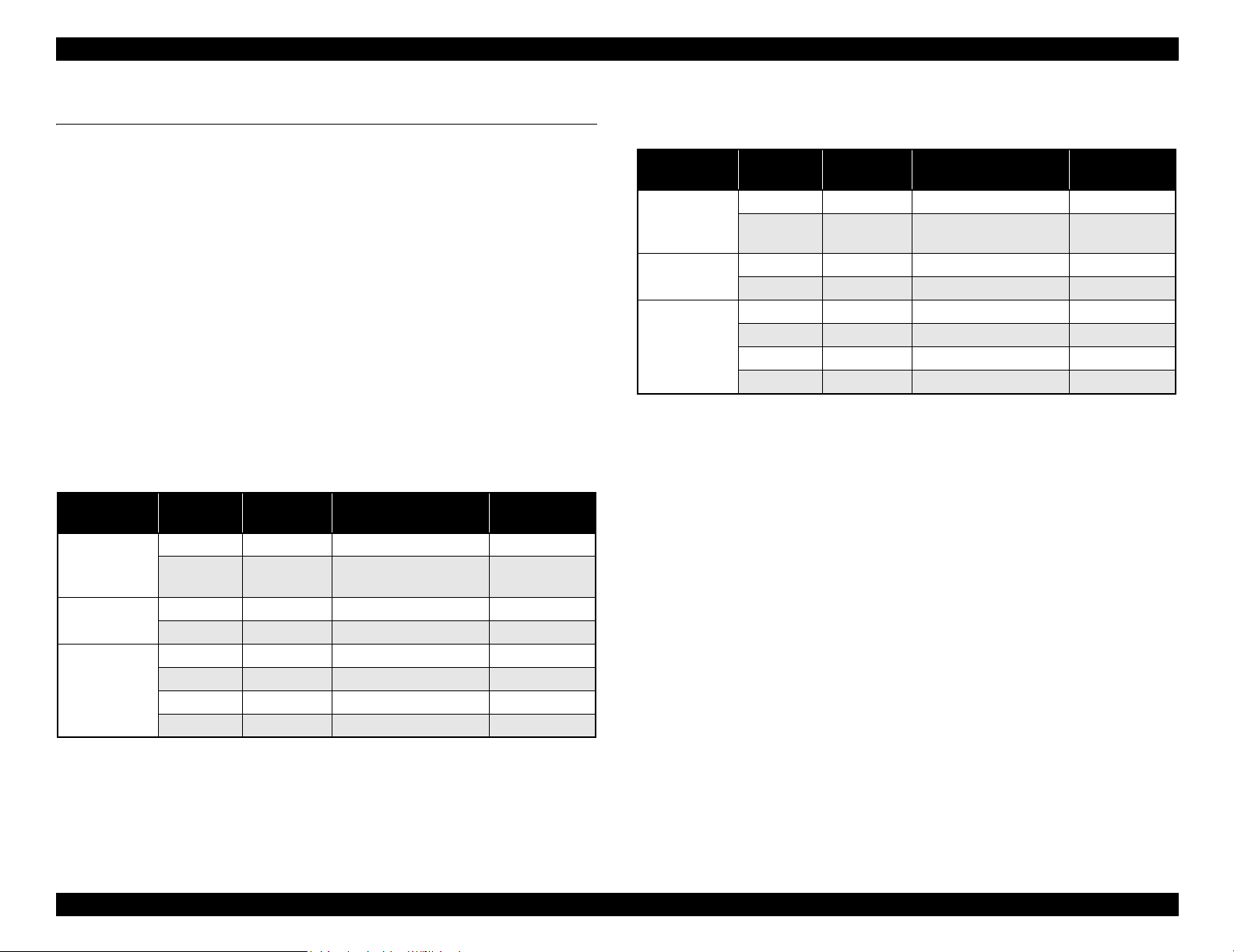
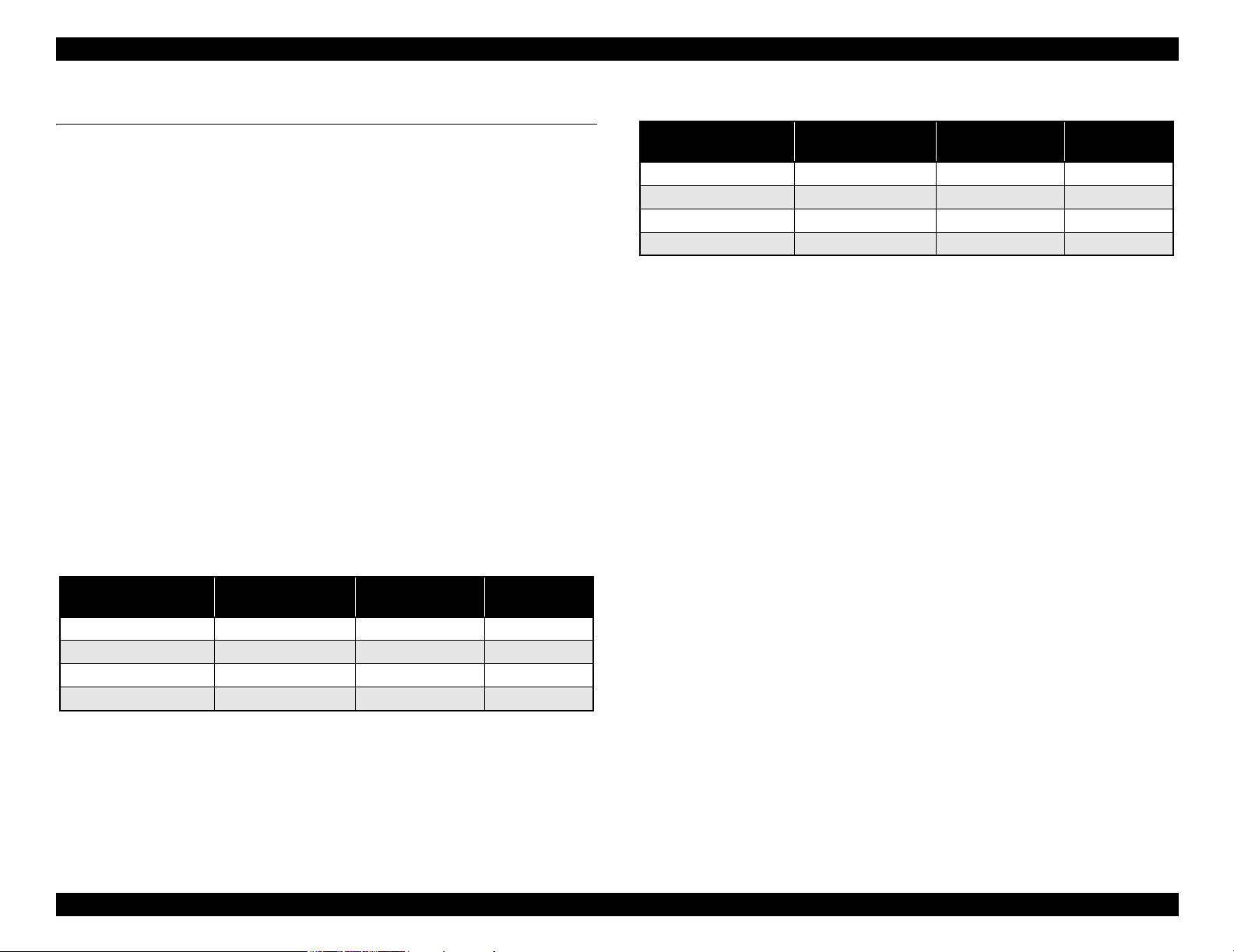
High-speed Throughput
Stylus Pro 7600
Table 1-1. Throughput (Stylus Pro 7600)
EPSON media Quality
Plain Paper Draft*
Doubleweight
Matte Paper
Glossy Photo
Paper
Glossy PaperHeavy Weight
1
Speed 360 × 360 Bi-D MF 240 cps 3/2 (BK×2*2)
Speed 360
Quality 720 × 360 Bi-DFOL(POL) 9 min
Speed 720
Quality 720 × 720 Bi-D 14POL 240 cps 13 min.
Adv.Photo 1440
Photo 2880 2880 × 1440 Bi-D 4-pass 190 cps 55 min
Resolution
(dpi)
360 × 180 Pseudo 4-color 2 min.
Mode
× 360 Bi-D M/W(POL) 240 cps 5 min.
× 360 Bi-D 22POL 240 cps 8 min.
× 720 Bi-D 4-pass 240 cps 25 min
Throughput
(A1 printing time)
min.
Stylus Pro 9600
Table 1-2. Throughput (Stylus Pro 9600)
EPSON media Quality
Plain Paper Draft*
Doubleweight
Matte Paper
Glossy Photo
Paper
Glossy PaperHeavy Weight
Note *1: Color high-speed 360×180dpi mode (for POP, for all ink combinations of pigment/
dye)
*2: Black double-speed mode (for CAD, supported with FW),
(It is switched automatically with 2 BK ink cartridge installation (dye/PPI) + M/W
OFF)
1
Speed 360 × 360 Bi-D MF 240 cps 6/3.5 (BK×2*2)
Speed 360
Quality 720 × 360 Bi-DFOL(POL) 17 min
Speed 720
Quality 720 × 720 Bi-D 14POL 240 cps 24 min
Adv.Photo 1440
Photo 2880 2880 × 1440 Bi-D 4-pass 190 cps 102 min
Resolution
(dpi)
360 × 180 Pseudo 4-color 3.5 min
Mode
× 360 Bi-D M/W(POL) 240 cps 9 min.
× 360 Bi-D 22POL 240 cps 14 min
× 720 Bi-D 4-pass 240 cps 46 min
Throughput
(A1 printing time)
min.
Super High Quality
High image quality with 7-color ink, 2880
layers.
×1440 dpi, and minimum 4pl various
Low Running Cost
• Independent for each color and 110 ml ink cartridge
• Large capacity 220 ml ink cartridge as an option
Paper Handling
• Support various media.
• Automatic roll paper cutter, manual cutter
• Automatic loading (cut sheet)
• Borderless print for right and left
Note *1 : Color high-speed 360×180dpi mode (for POP, for all ink combinations of pigment/
dye)
*2: Black double-speed mode (for CAD, supported with FW),
(It is switched automatically with 2 BK ink cartridge installation (dye/PPI) + M/W
OFF)
Compatibility with other LFPs
Commands are upper compatible with Stylus Pro 10000, Stylus Pro 10000CF,
Stylus Pro 9000, Stylus Pro 9500, Stylus Pro 7000, and Stylus Pro 7500.
The latest RIP technology
CPSI Pro software RIP
Product Description Product Description 12
EPSON Stylus Pro 7600/9600 Revision A
1.1.2 Differences between Stylus Pro 7600 and Stylus Pro
9600
Table 1-3. Differences between Stylus Pro 7600 and Stylus Pro 9600
Item Stylus Pro 7600 Stylus Pro 9600
Product
Specifications
Option Take-up Reel Unit Not supported
Maximum paper
width
RAM capacity 32MB (16Mbit×2)
(IC600/601 = not mounted)
220 ml ink
cartridge
610mm
(About 24 inches /
A1+size supported)
(CN30 = not mounted)
Not supported Spported
1118m
(About 44 inches /
B0+size supported)
64MB (16Mbit×4)
Spported
Product Description Product Description 13
EPSON Stylus Pro 7600/9600 Revision A
1.2 Basic Specifications
1.2.1 Print Specifications
Printing: On-demand ink-jet
Nozzle configuration:
Black: 192 nozzles (Black1, Black2, 96 nozzles each)
Color: 480 nozzles (cyan, magenta, light cyan, light magenta,
yellow, 96 nozzles each)
Nozzle pitch: 0.141mm (1/180 inch) for each color
Printing direction:
Bi-direction with logic seeking (high-speed return, high-speed skip only)
Printing speed and printable area
Character mode
• Character quality: high quality
• Character pitch: 10 cpi
• Printable area:
Stylus Pro 7600: 237 characters (at 10 cpi) / 8,561 dots (360dpi)
Stylus Pro 9600: 437 characters (at 10 cpi) / 15,840 dots (360dpi)
• Printing speed: 240 cps max.
Graphic Mode
Table 1-4. Graphics Modes (Stylus Pro 7600)
Horizontal resolution
(dpi)
360 604 mm (24.16 inches) 8698 240 cps
720 604 mm (24.16 inches) 17395 240 cps
1440 604 mm (24.16 inches) 34790 240 cps
2880 604 mm (24.16 inches) 69581 190 cps
Printable area
Maximum number
of printable dots
Printing speed
Table 1-5. Graphics Modes (Stylus Pro 9600)
Horizontal resolution
(dpi)
360 1112 mm (43.78 inches) 15762 240 cps
720 1112 mm (43.78 inches) 31524 240 cps
1440 1112 mm (43.78 inches) 63048 240 cps
2880 1112 mm (43.78 inches) 126087 190 cps
Printable area
Maximum number
of printable dots
1.2.2 Character Specification
Character tables: 2 international character sets
PC 437 (US, Standard Europe)
PC 850 (Multilingual)
NOTE:
This specification is not described in the user's manual.
Typeface:
Bit map LQ font: EPSON Courier 10 cpi
NOTE:
This specifications is not described in the user's manual.
1.2.3 Control Code
Control code:
ESC/P Raster
ESC/P3
NOTE:
This specifications is not described in the user's manual.
1.2.4 Paper Feed
Paper feeding: Friction feed
Line spacing: 1/6 inch or programmable at 1440 inch
Paper path: Roll paper/manual
Feed speed: 6.35 mm paper feed: 215 ± 10 msec
(except front rush, back rush, and hold time)
Printing speed
Product Description Basic Specifications 14
EPSON Stylus Pro 7600/9600 Revision A
1.2.5 Paper Specifications
1.2.5.1 Roll Paper
ACCEPTABLE PAPER
The printer accepts following plain paper and EPSON special paper. With any other
paper, proper paper feeding and satisfactory print quality are not ensured.
Paper Size
Table 1-6. Acceptable Roll Paper Sizes (Acceptable Paper)
Core Model Paper Size
2-inch core Stylus Pro 7600 203mm ~ 610 mm (W)
Stylus Pro 9600 203 mm ~ 1118 mm (W) × ~ 45 m (H) *
3-inch core Stylus Pro 7600 203 mm ~ 610 mm (W)
Stylus Pro 9600 203 mm ~ 1118 mm (W) × ~ 202 m (H) *
Note "* " : Within roll size
Roll Size
2-inch core: 103 mm ext. diameter maximum for 1 roll setting
3-inch core: 150 mm ext. diameter maximum for 1 roll setting
Thickness: 0.08 mm ~ 0.50 mm
× ~ 45 m (H) *
× ~ 202 m (H) *
PLAIN PAPER
Trouble-free paper feeding is ensured only in the following specifications.
Paper Size
Table 1-7. Acceptable Roll Paper Sizes (Plain Paper)
Core Model Paper Size
2-inch core Stylus Pro 7600 203 mm ~ 610 mm (W)
Stylus Pro 9600 203 mm ~ 1118 mm (W) × ~ 45m (H) *
3-inch core Stylus Pro 7600 203 mm ~ 610 mm (W)
Stylus Pro 9600 203 mm ~ 1118 mm (W) × ~ 202m (H) *
Note "* " : Within roll size
× ~ 45m (H) *
× ~ 202m (H) *
Roll Size
2-inch core: 103 mm ext. diameter maximum for 1 roll setting
3-inch core: 150 mm ext. diameter maximum for 1 roll setting
Thickness: 0.08 ~ 0.11 mm
Weight: 64 ~ 90gf/m
2
Type: Plain paper, Recycle paper
Product Description Basic Specifications 15
EPSON Stylus Pro 7600/9600 Revision A
BORDERLESS PRINT ROLL PAPER
Borderless print for right and left is enssured for roll paper with any of the paper widths
as specified in Figure 1-9 below.
NOTE: 300 mm, 400 mm, 500 mm and 600 mm are supported for Europe.
Paper width
Table 1-8.
Stylus Pro 7600
Stylus Pro 9600
Japan 8”
USA/Europe 8”
Note 1: Paper should have no wrinkles, tears, or folds and the surface should be smooth.
2: The force to remove the end of the roll paper from the core should be between 300 gf
and 2000 gf
3: If core is used, a product-exclusive option (roll paper spindle 3 inch) is necessary.
4: It is used under normal conditions. (temperature 15
5: Roll paper can be printed before paper comes out of the core.
(Reference: Remaining paper length is 30cm approx. when roll paper come out of the
core.)
6: The mechanism clips print data out of over-printable area for borderless printing.
210
10” - 12” 14” - 16” - 20” - 24” 36” 44”
mm
210
mm
10”
300
mm
12” 14”
400
mm
16”
500
mm
20”
600
24” 36” 44”
mm
°C ~ 25°C, humidity 40 ~ 60%RH)
1.2.5.2 Sheet
ACCEPTABLE PAPER
The printer accepts following plain paper and special paper. With any other paper,
proper paper feeding and satisfactory print quality are not ensured.
Paper Size (The sizes indicated in bold italic are only for Stylus Pro 9600.)
Table 1-9. Acceptable Sheet Sizes (Acceptable Paper)
Paper Size Size (W × H) Paper Size Size (W × H)
B0+* 1118 mm
B0 * 1030 mm × 1456 mm US E 34 × 44 in
B1 * 728 mm
B2 515 mm × 728 mm US C 17 × 22 in
B3 364 mm
B4 257 mm × 364 mm 44 × 36 in * 44 × 36 in
A0+ * 914 mm
A0 * 841 mm × 1189 mm Letter 8.5 × 11 in
A1+ 24
A1 594m × 841 mm 8 × 10 in 8 × 10 in
A2 420 mm
A3+ 329 mm × 483 mm 60 cm × 90 cm 60 cm × 90 cm
A3 297 mm
× 1580 mm A4 210 mm × 297 mm
× 1030 mm US D 22 × 34 in
× 515 mm US B 11 × 17 in
× 1292 mm 30 × 24 in 30 × 24 in
× 36 in B1 (wide) * 1030 × 728 mm
× 594 mm 30 cm × 45 cm 30 cm × 45 cm
× 420 mm
Note " * " : Only for Stylus Pro 9600
Thickness
0.08 ~ 1.5 mm (paper length: 279 mm ~ 728 mm)
0.08 ~ 0.5 mm (paper length: 728 mm ~ 1580 mm)
NOTE 1: Paper should have no wrinkles, tears, or folds and the surface should be
smooth.
2:
0.08 ~ 1.50 mm paper thickness is supported for long-edge insertion.
3:
The sizes indicated in bold italic are only for Stylus Pro 9600.
Product Description Basic Specifications 16
EPSON Stylus Pro 7600/9600 Revision A
PLAIN PAPER
Proper feeding is ensured only in the following specifications.
Paper Size: Same as above list
Thickness: 0.08 ~ 0.11 mm
Weight: 64 ~ 90 gf/m
2
Type: Plain paper, Recycle paper
NOTE 1: Paper is fed short-edge first.
2:
Paper should have no wrinkles, tears, or folds and the surface should be
smooth.
3:
It is used under normal conditions (temperature 15
60%RH)
4:
300mm, 400mm, 500mm, 600mm are supported for Europe.
5:
Mechanism clips print data out of over-printable area for borderless print.
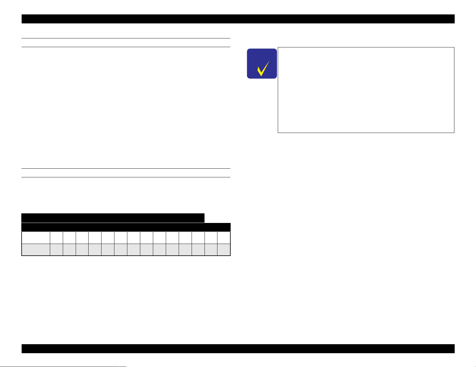
BORDERLESS PRINT WIDTH
Borderless print for right and left is assured with following paper width. *4
~
25°C, humidity 40
C H E C K
P O I N T
~
Description of units of measure
cpi: characters per inch
dpi: dots per inch
cps: characters printed per second (at 10 cpi)
1 cps = 2.54 mm/s
ips: travel in inches per second
1 ips = 25.4 mm/s
G: Gravity
General ambient conditions:
Temperature 15
°C ~ 25°C
Humidity 40% ~ 60%
Paper width
Table 1-10.
Stylus Pro 7600
Stylus Pro 9600
210
Japan 8”
USA/Europe 8”
Product Description Basic Specifications 17
10” - 12” 14” - 16” - 20” - 24” 36” 44”
mm
210
mm
10”
300
mm
12” 14”
400
mm
16”
500
mm
20”
600
24” 36” 44”
mm
EPSON Stylus Pro 7600/9600 Revision A
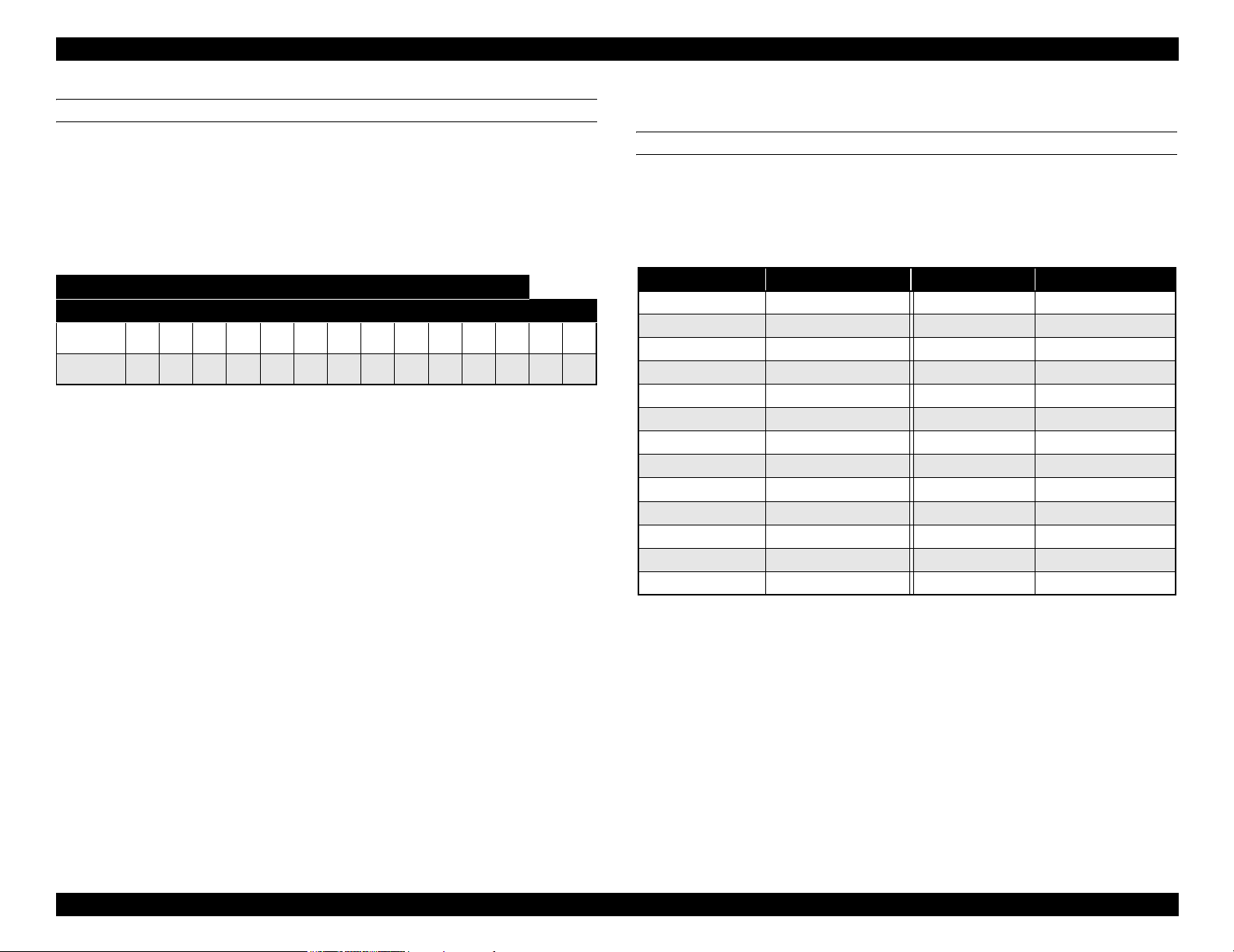
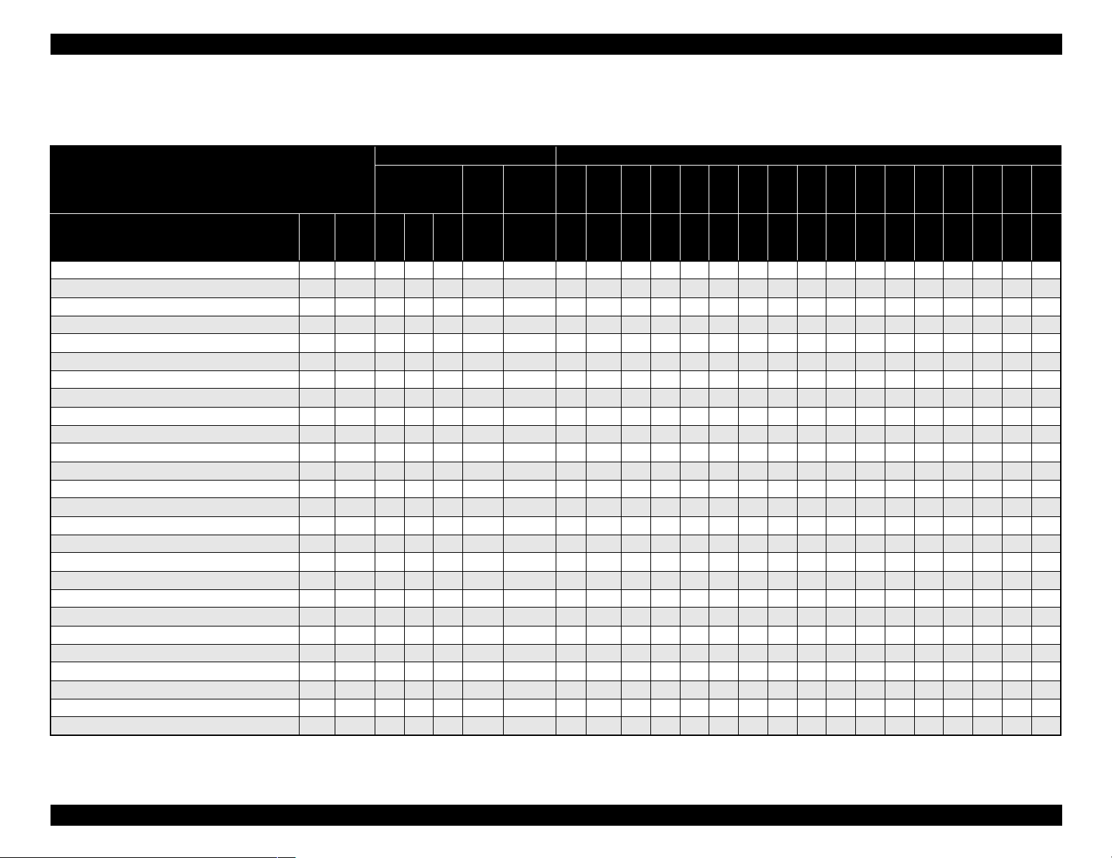
1.2.5.3 Special Paper
Roll (pigment)
Table 1-11. Availability with Special Paper (Pigment)
Characteristic Media Size
Roll / Pigment
Name Japan
Doubleweight Matte Paper
Glossy Paper - Photo Weight
Glossy Film
Premium Glossy Photo Paper
Premium Semigloss Photo Paper
Photo Glossy Paper / Photo Grade Glossy Paper
Photo Semigloss Paper / Photo Grade Semigloss Paper
Premium Glossy Photo Paper (250)
Premium Semigloss Photo Paper (250)
Premium Semimatte Photo Paper (250)
Premium Luster Photo Paper
Watercolor Paper - Radiant White
Smooth Fine Art Paper (Roll)
Textured Fine Art Paper (Roll)
Canvas
Backlight Film
Backlight Film (USA / Europe)
Heavyweight Polyester Banner
Enhanced Synthetic Paper
Adhesive Enhanced Synthetic Paper
Tyvek Brillion
Adhesive Vinyl
Enhanced Matte Paper
Semiglossy 2
Semiglossy 4
Dupont / EPSON Semi - Gloss Proofing Paper - A
Black INK
USA/
MK×2MK
Europe
/Asia
{{zz{20.21~ ------------~~~
{ { { 2 0.22 ~ - - - - - - - - - - ~ - - ~ ~
{{ {20.13~ ------------~~~
{ { { 2 0.18 ~ - - - - - - - - - - - - ~ ~ ~
{{ {20.18~ ------------~~~
{ { { 2 0.17 ~ - - - - - - - - - - - - ~ ~ ~
{{ {20.18~ ------------~~~
{ { { 3 0.26 ~ ~ - - - - - - - - - - - - ~ ~ ~
{{ {30.26~~ ------------~~~
{ { { 3 0.26 ~ ~ - - - - - - - - - - - - ~ ~ ~
{{ {30.26~~ --~~~~~ ~~ - ~~~~
{ { { { 3H 0.29 ~ - - - - - - - - - - - - ~ ~ ~
{{{3H 0.37 ------------~~~
{ { { { 3H 0.37 - - - - - - - - - - - - ~ ~ ~
{{{2 0.46 ------------~~~
{ { 2 0.13 ~ - - - - - - - - - - - - ~ ~ ~
{{2 0.18 ------------~~~
{ { z { 2 0.28 - - - - - - - - - - - - ~ ~ ~
{{zz{2H 0.12 ~ ------------~~~
{ { z z { 2H 0.17 ~ - - - - - - - - - - - - ~ ~ ~
{zz{ 20.24~ ------------~~~
{ z z { 2 0.33 - - - - - - - - - - - - ~ ~ ~
{{ {{30.25~ ------------~~~
TBD TBD { 2 TBD ~ - - - - - - - - - - - - ~ ~ -
{{2TBD~ ------------~~ -
{ { 2 0.20 - - - - - - - - - - - - ~ ~ -
+LKPK+LK
core”
spindle
Paper
thickness
(mm)
Auto
cut
Borde
rless
210
8”
mm
203 210 254 300 305 356 400 406 500 508 560 600 610 914 1118
10”
30
cm
12” 14”
40
cm
16”
50
cm
20” 22”
60
cm
24” 36” 44”
Note : Symbol ~: Assured, {: Supported, z: Supported conditionally, ×: Not supported, 2H/3H: High tension spindle
Product Description Basic Specifications 18
EPSON Stylus Pro 7600/9600 Revision A
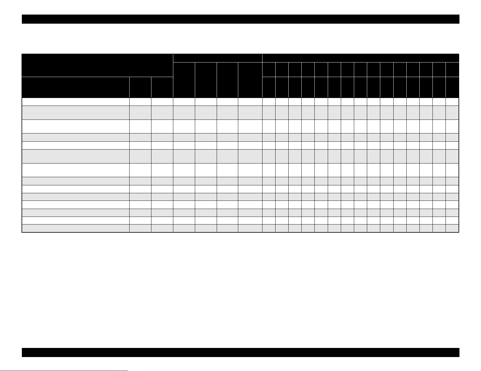
Roll (dye)
Table 1-12. Availability with Special Paper (Dye)
Characteristic Media Size
Roll / Dye
Name Japan
Presentation Matte Paper
Semigloss Photo Paper (Asia / Europe)
Semi Gloss Paper - Heavy Weight (US)
Glossy Photo Paper (Asia / Europe)
Glossy Paper - Heavy Weight (US)
Doubleweight Matte Paper
Glossy Film
Photo Grade Glossy Paper (Asia / Europe)
Photo Glossy Paper (US)
Photo Grade Semigloss Paper (Asia / Europe)
Photo Semigloss Paper (US)
Heavyweight Polyester Banner
RC 10mil Glossy Paper (TBD)
RC 10mil Semigloss Paper (TBD)
Premium Luster Photo Paper
Dupont / EPSON Commercial Proofing Paper
Dupont / EPSON Commercial Matte Proofing Paper
Dupont / EPSON Publication Proofing Paper
USA/
Europe/
Asia
{{ 20.20{ ------------~~~
{ { 2 0.21 { - - - - - - - - - - - - ~ ~ ~
{{ 20.23{ ------------~~~
{ 2 0.21 { - - - - - - - - - - - - ~ ~ ~
{{ 20.13{ ------------~~~
{ 2 0.17 { - - - - - - - - - - - - ~ ~ ~
{ 20.18{ ------------~~~
{ { 2 0.28 - - - - - - - - - - - - ~ ~ ~
TBD { 30.26{ ----------- ~~~
TBD { 3 0.26 { - - - - - - - - - - - - ~ ~ ~
TBD { 30.26{~--~~~~~~~~ - ~~~~
{ 2 0.21 { - - - - - - - - - - - - ~ ~ { 20.24{ ------------~~ { 2 0.24 { - - - - - - - - - - - - ~ ~ -
core”
spindle
Paper
thickness
(mm)
Auto cut Borderless
210
8”
203 210 254 300 305 356 400 406 500 508 560 600 610 914 1118
10” 30cm 12” 14” 40cm 16” 50cm 20” 22” 60cm 24” 36” 44”
mm
Note : Symbol ~: Assured, {: Supported, z: Supported conditionally, ×: Not supported, 2H/3H: High tension spindle
Note *1: Assured with Uni-D print.
*2: Paper is fed short-edge first.
*3: Paper should have no wrinkles, tears, or folds and the surface should be smooth.
*4: It is used under normal conditions (temperature 15°C ~ 25°C, humidity 40% ~ 60%RH)
*5: Paper feeding and print quality with borderless print is not assured on paper which is not assured for borderless print.
*6: Borderless print is not assured with sheet.
Product Description Basic Specifications 19
EPSON Stylus Pro 7600/9600 Revision A
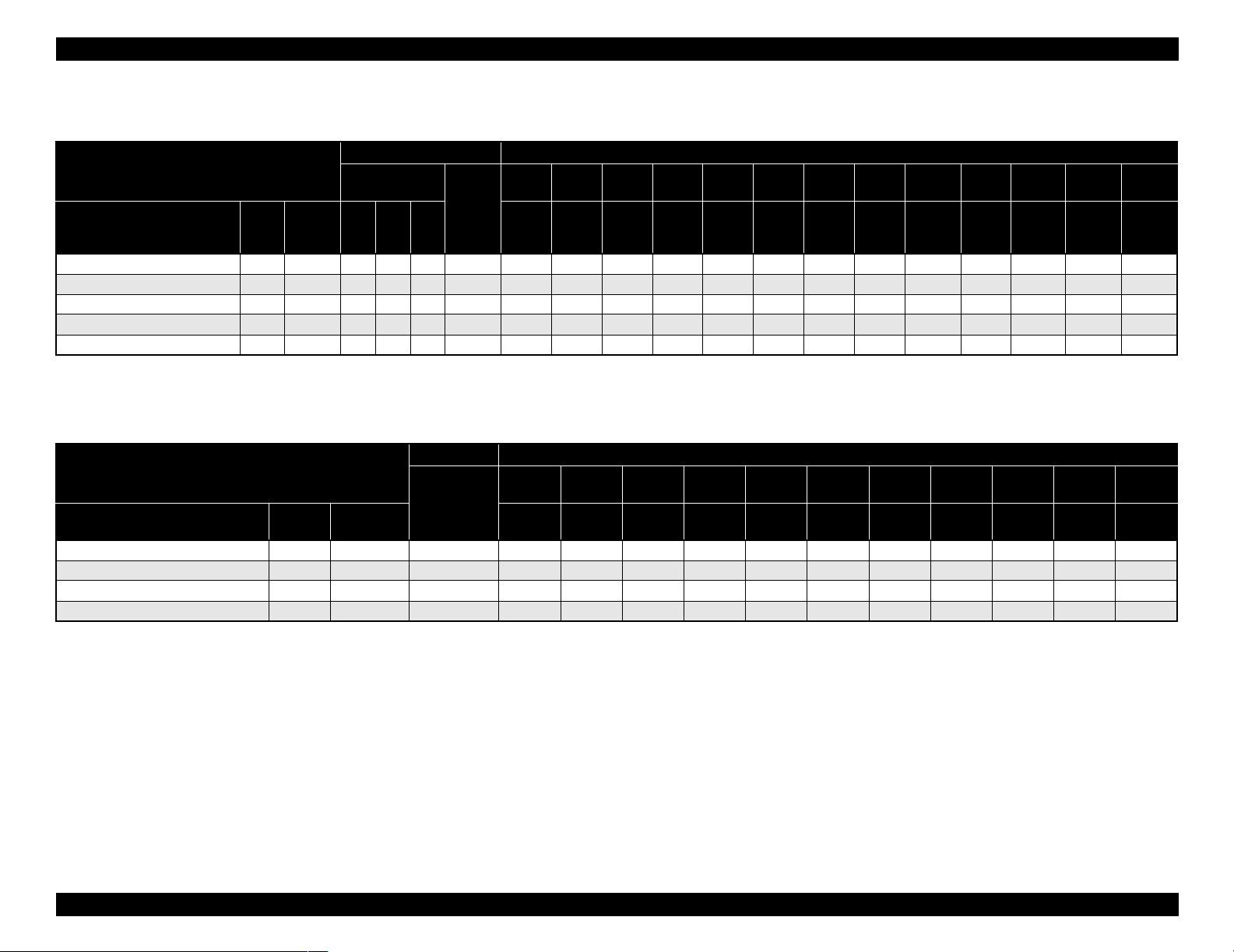
Sheet (pigment)
Table 1-13. Availability with Sheets (Pigment)
Characteristic Media size
Sheet / Pigment
Name Japan
Glossy Paper - Photo Weight
Watercolor Paper - Radiant White
Smooth Fine Art Paper
Textured Fine Art Paper
Enhanced Matte - Poster Board
USA/
Europe/
Asia
{{ { ~~~~~ ------- { { { { - - - - ~ - - - - - - - -
{{{0.67-------- - -~ - ~
TBD { { { 0.67 - - - - - - - - - - ~ - ~
{{ {{1.3 ------ - -~~ -
Black INK
MK×2MK
+LKPK+LK
Paper
thickness
(mm)
A4 LTR A3 B
210×297 216×279 297×420 279×432 329×483 420×594 432×559 515×728 728×1030 559×864 610×762 762×1016 914×1118
Note : Symbol ~: Assured, {: Supported, z: Supported conditionally, ×: Not supported, 2H/3H: High tension spindle
Super
A3/B
A2 C B2 A1 D 24”×30” 30”×40” 36”×44”
Sheet (dye)
Table 1-14. Availability with Sheets (Dye)
Characteri stic Mediasize
Sheet / Dye
Name Japan
Glossy Photo paper
Photo Quality Inkjet Paper
Glossy Film
Semigloss Paper - Poster Board
Paper
USA/Europe
/Asia
{ { ~~~~~ -----{ { ~ ~ ~ ~ ~ ~ ~ - - - { { ~~~~~ -----
{ - - - - - - - ~ - - ~
thickness
A4 LTR A3 B
210×297 216×279 297×420 279×432 329×483 420×594 432×559 515×728 728×1030 559×864 728×1030
Super
A3/B
A2 C B2 A1 D B1”
Note : Symbol ~: Assured, {: Supported, z: Supported conditionally, ×: Not supported, 2H/3H: High tension spindle
Note *1: Assured with Uni-D print.
*2: Paper is fed short-edge first.
*3: Paper should have no wrinkles, tears, or folds and the surface should be smooth.
*4: It is used under normal conditions (temperature 15°C~25°C, humidity
40%~60%RH)
Product Description Basic Specifications 20
EPSON Stylus Pro 7600/9600 Revision A
1.2.6 Mechanism Specifications
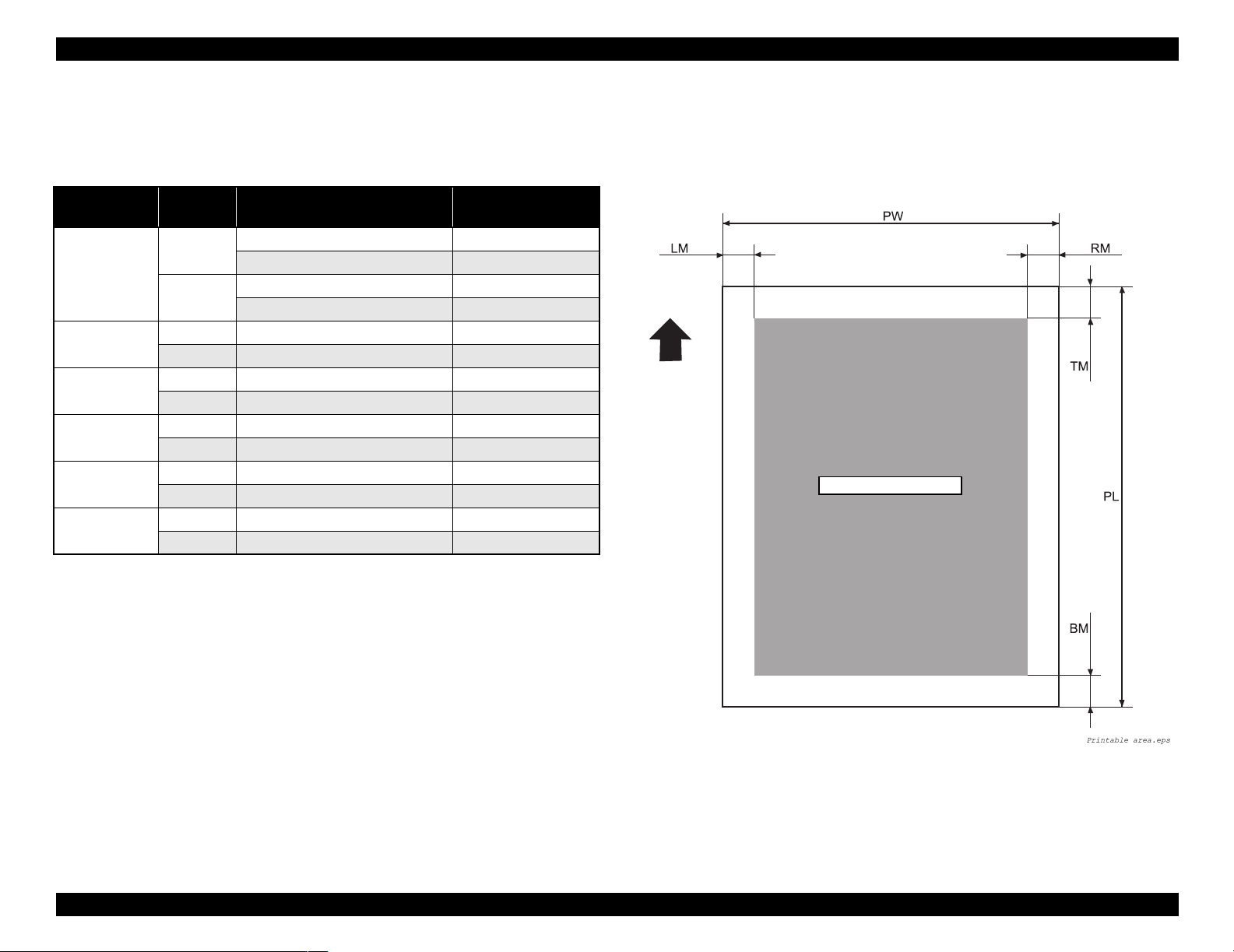
1.2.6.1 Printable Area
Table 1-15. Printable Area
Item
PW
(Paper width)
PL
(Paper length)
TM
(Top margin)
BM
(Bottom margin)
LM
(Left margin)
RM
(Right margin)
Roll paper
/Sheet
Roll paper Stylus Pro 7600 203 mm ~ 610 mm
Stylus Pro 9600 203 mm ~ 1118 mm
Sheet Stylus Pro 7600 203 mm ~ 610 mm
Stylus Pro 9600 203 mm ~ 1118 mm
Roll paper Stylus Pro 7600/Stylus Pro 9600 Max. 202m
Sheet Stylus Pro 7600/Stylus Pro 9600 279 mm ~ 1580 mm
Roll paper Stylus Pro 7600/Stylus Pro 9600 3 mm/15 mm
Sheet Stylus Pro 7600/Stylus Pro 9600 3 mm
Roll paper Stylus Pro 7600/Stylus Pro 9600 3 mm/15 mm
Sheet Stylus Pro 7600/Stylus Pro 9600 14 mm
Roll paper Stylus Pro 7600/Stylus Pro 9600 0 mm/3 mm/15 mm
Sheet Stylus Pro 7600/Stylus Pro 9600 0 mm/3 mm
Roll paper Stylus Pro 7600/Stylus Pro 9600 0 mm/3 mm/15 mm
Sheet Stylus Pro 7600/Stylus Pro 9600 0 mm/3 mm
Model Dimension
For borderless print, right and left margins are 3mm each because skew detection
limit is 3mm. If the distance from the paper edge to the platen (sponge width) is
less than 3mm, the maximum surplus print quantity without ink discharge onto the
platen (0mm~3mm) is printable area.
Paper Feed Direction
Printable Area
The printer detects paper width when paper is set. (If paper width detection setting
is OFF, it does not detect paper width.)
It does not print the image beyond the detected paper width or the printable area
specified by paper size setting.
(It may print on the platen if paper width detection setting is OFF.)
Margins of roll paper can be changed on the panel as follows;
Top/bottom 15 mm, left/right 3 mm
Top/bottom/left/right 3 mm
Top/bottom/left/right 15 mm
NOTE:
Under special conditions, it is possible to set right and left margin (LM,
RM) to 0.
Product Description Basic Specifications 21
Figure 1-1. Printable Area
EPSON Stylus Pro 7600/9600 Revision A
1.2.6.2 Paper Set Lever
Table 1-16. Paper Set Lever
Lever Position Description
In the rear Position for paper setting
(You can set paper.)
In the front Ready-to-print position
(Paper is held with the paper holder.)
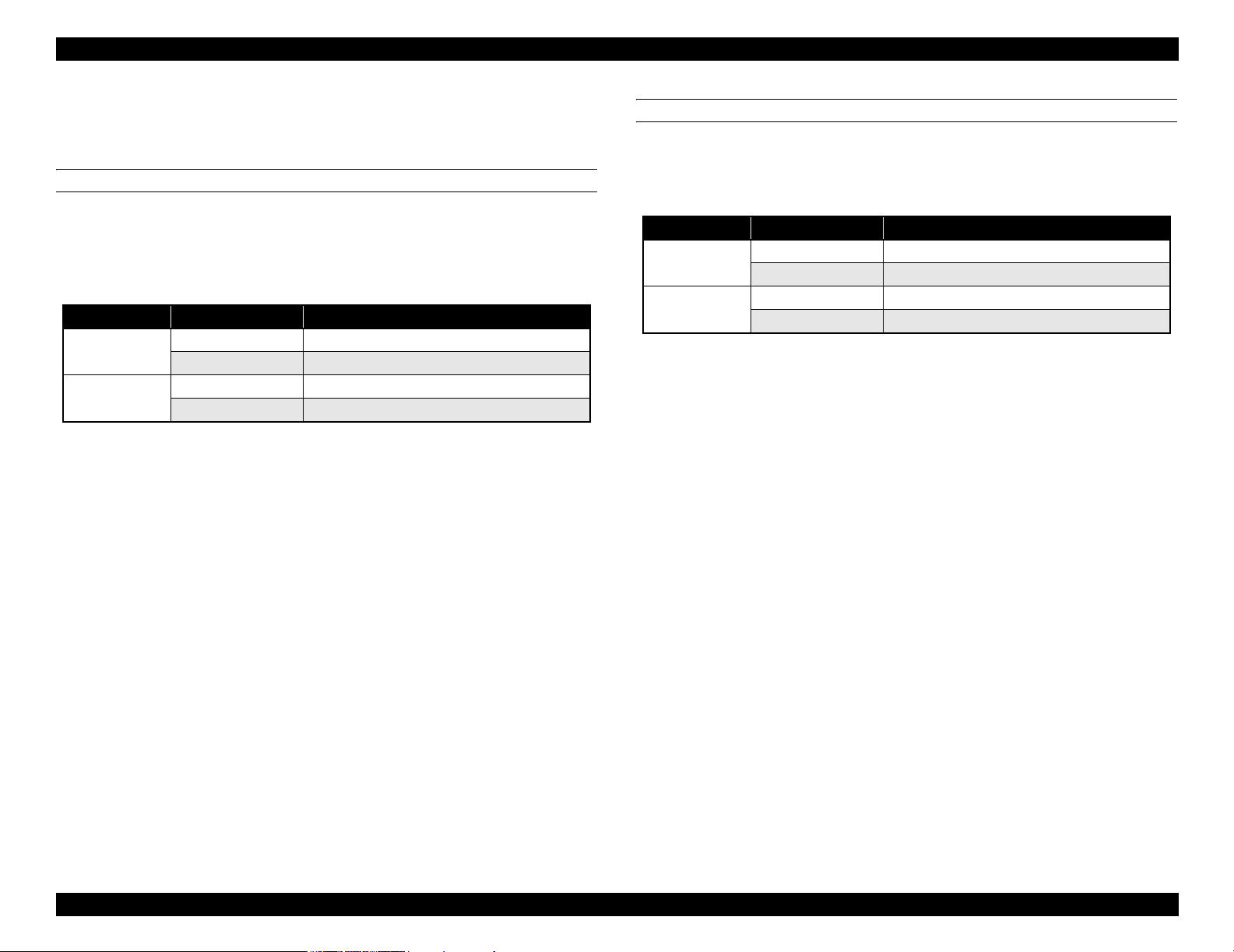
1.2.6.3 Cutting Specification
There are two methods to cut roll paper, automatic and manual cutting.
C A U T I O N
AUTOMATIC CUTTING OF ROLL MEDIA
Automatic cutting under the following conditions can only be performed on the
approved media.
Mechanical conditions
Distance between cut position and paper setting position: L0=167mm
Distance between cut position and cutter mark: L1= 44mm
Minimum cut length (same as paper edge waiting position): L2=030mm
Do not use the auto cutting function with any paper for which auto
cutting is prohibited; otherwise, the head would be damaged.
Table 1-17. Cutting Conditions and Cutting Methods
Cut condition Cut method
Initial cut (Cut with pushing “Cut/Eject” button after paper
is set, and set lever is pushed down.)
Cut after print completed by driver
Initial cut during printing
Initial cut during normal waiting status
Initial cut with Auto cut ON after print with Auto cut OFF.
Cut with Paper width detection OFF 3-step cut always (100cps fixed)
Note : Cutting pressure at high speed can be changed.
Cutting pressure at low speed is “Duty: 45%” fixed.
Paper edge waiting position is fed L2 for initial cut.
Paper is fed for L1 length and cut in 4 steps.
(50cps)
4-step cut (200cps) When paper is shorter
than L2, it is cut after feeding L2.
Cut during printing is not allowed with this
printer. (Product specification)
Paper is fed for L1 length and cut in 4 steps.
(50cps)
4-step cut (200cps), when paper is longer
than L2. 4-step cut (50cps) after feeding L2,
when paper is shorter than L2.
MANUAL CUTTING OF ROLL PAPER
Manual cutting is performed by the following procedure.
1. Select “Roll Cutter Off” on the panel.
2. Press “Cut/ Eject” button.
3. Paper is automatically fed toward the cutter guide, and printer becomes Off-line.
“Pause” is indicated on the LCD panel.
4. Adjust cutting position with “Paper Feed +/-” button if necessary.
5. Slide the cutter along the cutter guide to cut the paper.
6. After cutting, release the printer from the pause status by pressing the “Pause”
button. Then paper is fed backward and printer enters on-line.
C H E C K
P O I N T
For manual cutting of roll paper, use the manual cutter available as
an option.
Product Description Basic Specifications 22
EPSON Stylus Pro 7600/9600 Revision A
1.2.6.4 Acoustic Noise
Level: Approx. 50dB(A) (According to ISO 7779)
1.2.7 Electrical Specifications (TBD)
Rated voltage: AC 100 ~ 240V
Input voltage range: AC 90 ~ 264V
Rated frequency range: 50 ~ 60Hz
Input frequency range: 49 ~ 61Hz
Rated current:
Stylus Pro 7600: 1.0A/100-120v, 0.5A/220-240v
Stylus Pro 9600: 1.0A/100-120v, 0.5A/220-240v
Power consumption:
Operation status: Stylus Pro 7600 50W
Stylus Pro 9600 55W
Waiting status: Less than 15W (shifting time: 15 minutes)
Power OFF: Less than 0.7W
Insulation resistance: More than 10M ohms
(between AC line and chassis, DC 500V)
Dielectric strength: AC 1.0kV rms 1min.
AC1.2kV rms 1 sec.
(between AC line and chassis)
1.2.8 Reliability
1.2.8.1 Total Print Volume
Stylus Pro 7600: 50,000 pages, 6.5million pass approx. (A1, 360×360 M/F, Bi-D)
Stylus Pro 9600: 20,000 pages, 5million pass approx. (B0, 360×360 M/F, Bi-D)
1.2.8.2 Print Head Life
Monochrome: 28billion shot / nozzle
Color: 28billion shot / nozzle
1.2.8.3 Maintenance Tank Life
Stylus Pro 7600: 11,000 pages approx.
(A1, plain paper, Speed mode, continuous print)
Stylus Pro 9600: 5,000 pages approx.
(B0, plain paper, Speed mode, continuous print)
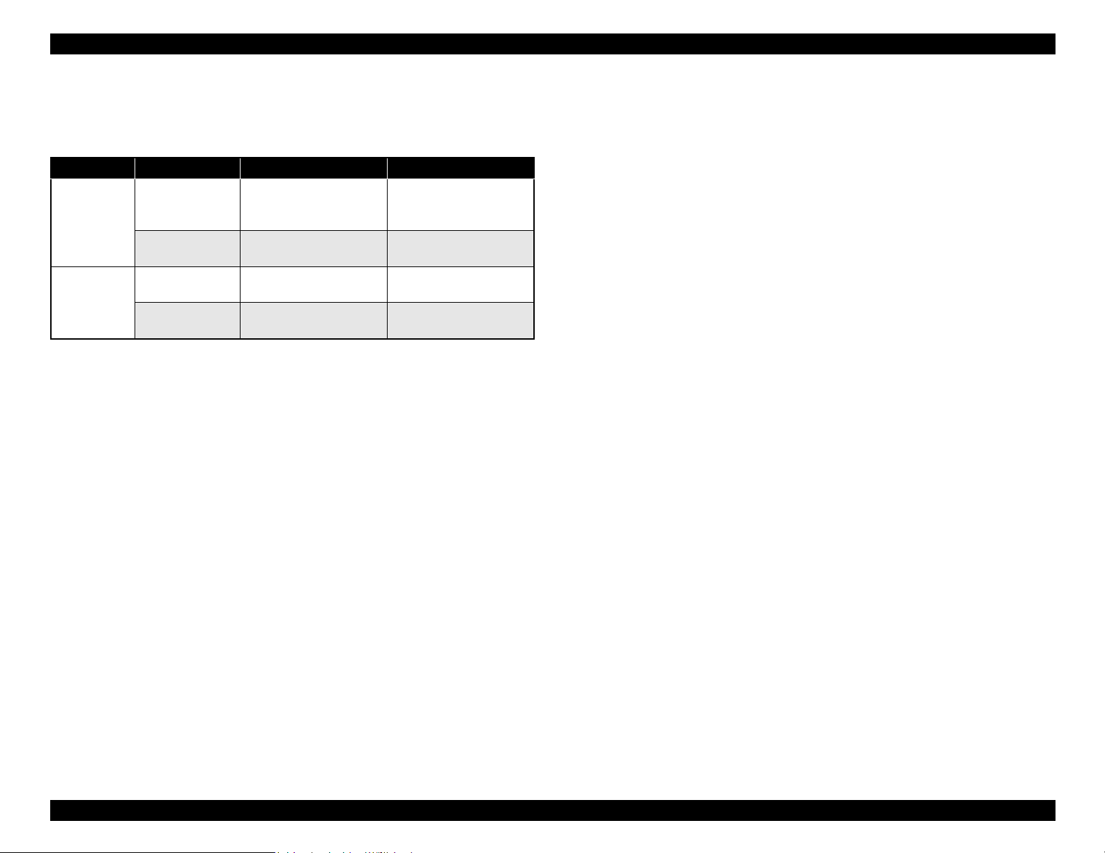
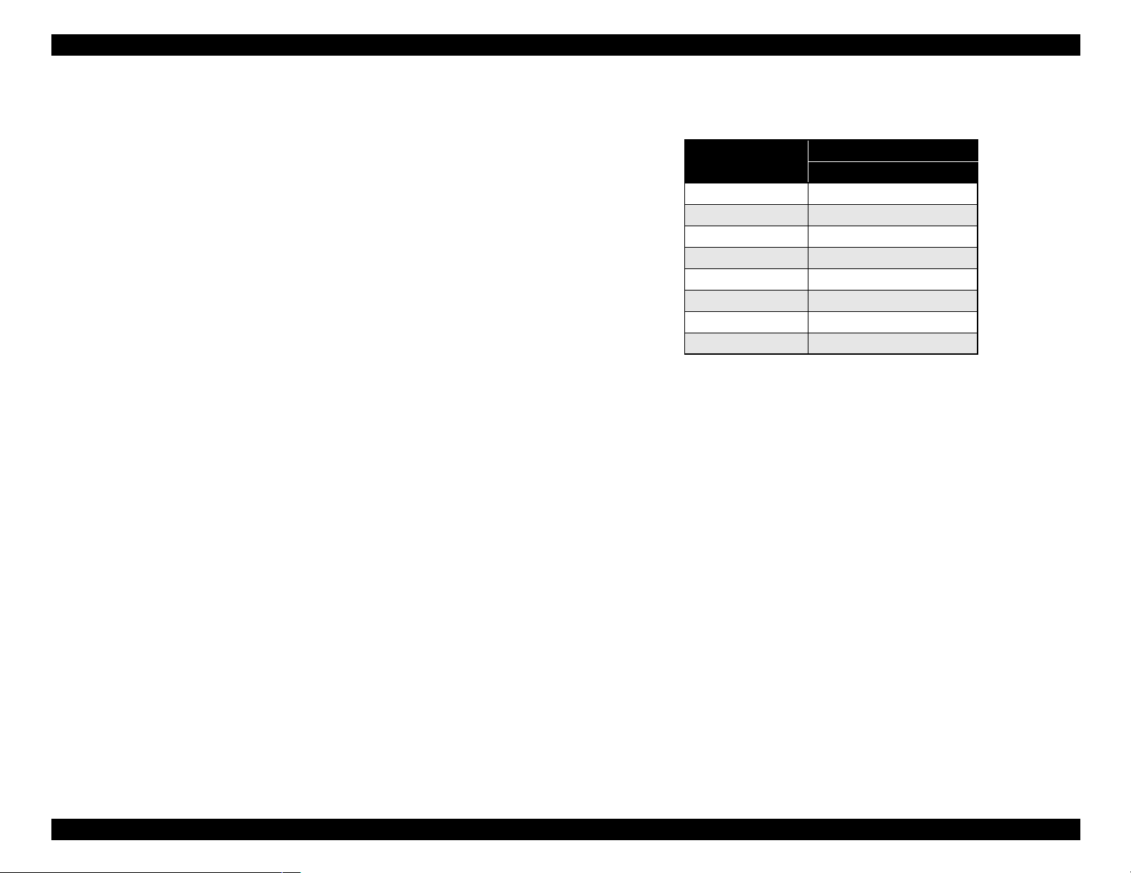
1.2.8.4 Cutter Life average
Table 1-18. Cutter life average
Stylus Pro 7600
Paper Type
Coated paper Approx. 2000 sheets Approx. 2000 sheets
Film Approx. 1000 sheets Approx. 1000 sheets
For 24-inch standard roll paper,
3-step cutting
For 44-inch standard roll paper,
Stylus Pro 9600
3-step cutting
Leakage: Less than 0.25mA
International Energy Star Program Compliant:
(Complies with the power supply harmonic control
guideline)
1.2.8.5 Maintenance Parts (TBD)
RTC backup battery: (TBD)
Cleaning unit life average
(Cap assembly, Pomp assembly, Flushing box, Wiper)
Stylus Pro 7600: 18,000 pages approx.
(A1, plain paper, Speed mode, continuous print)
Stylus Pro 9600: 8,000 pages approx.
(B0, plain paper, Speed mode, continuous print)
Ink absorbent sponge for right/left borderless print: (TBD)
Product Description Basic Specifications 23
EPSON Stylus Pro 7600/9600 Revision A
1.2.9 Ambient Conditions
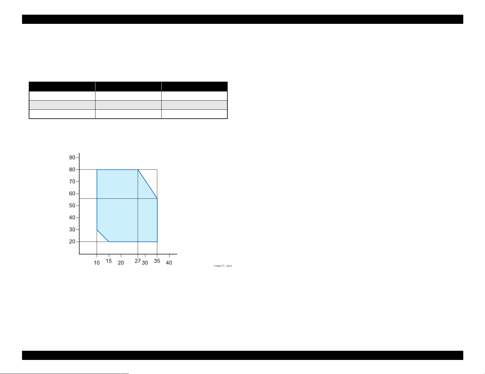
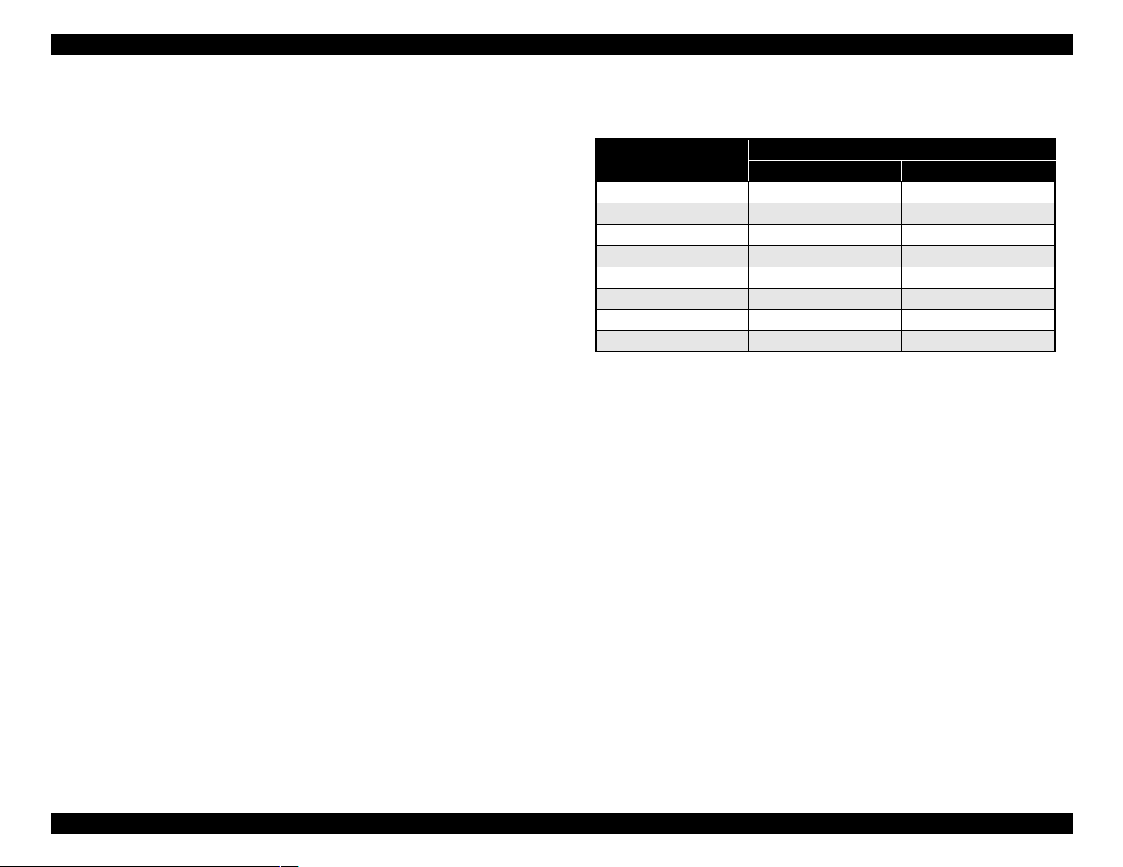
1.2.9.1 Temperature/Humidity
Table 1-19. Temperature/Humidity
Condition Temperature*
During operation 10 ~ 35°C 20 ~ 80%
During storage -20 ~ 40°C 20 ~ 85%
During transport -20
Note *1 : 120 hours max. at 60°C, one month max. at 40°C
*2: No condensation. These values are applicable only within the range as shown below.
Humidity (%)
~ 60°C 5 ~ 85%
1
Humidity*
1.2.9.3 Shock
During operation: 1G, 1ms max. X,Y and Z directions
During storage: 2G, 2ms max. X,Y and Z directions
NOTE 1: For storage, check that the print head is capped.
2
2:
Before transportation, check that the print head is capped, remove the ink
cartridges, and close the ink cartridge cover .
3:
If the power to the printer is OFF with the printer head uncapped, turn the
power ON with the ink cartridges installed. Then wait until capping is
completed, and turn the power OFF.
4:
If the printer is left standing at temperature of -15°C or below, the ink in the
print head and ink cartridges will freeze. If the ink is frozen, leave the printer
standing at temperature of 25°C for more than three hours before its use.
Temperature (°C)
Figure 1-2. Environmental Conditions: Temperature/Humidity
1.2.9.2 Vibration
During operation: 0.15G, 10 ~ 55Hz X,Y and Z directions
During storage: 0.50G, 10 ~ 55Hz X,Y and Z directions
Product Description Basic Specifications 24
EPSON Stylus Pro 7600/9600 Revision A
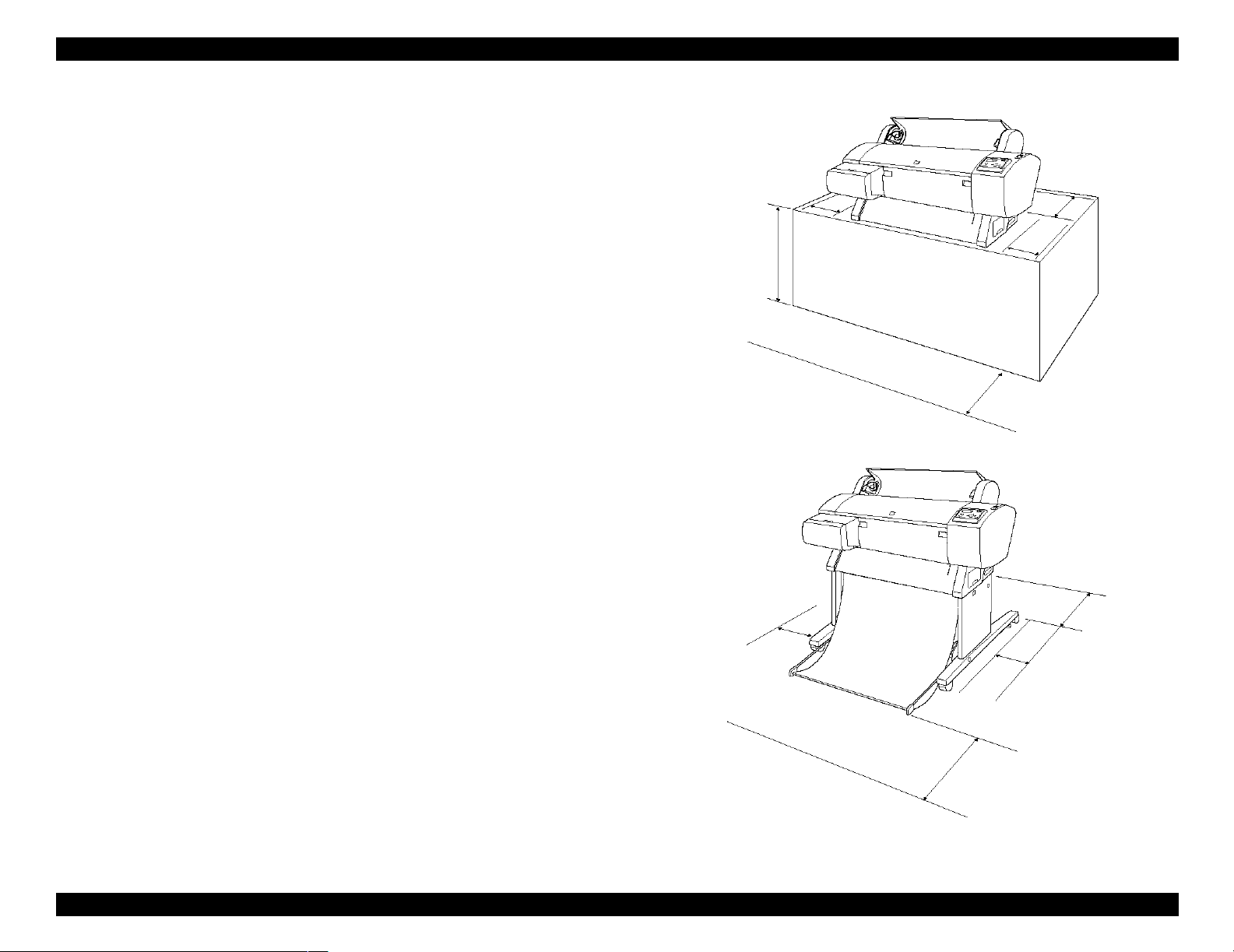
1.2.9.4 Surrounding Space
Provide the printer with an enough surrounding space to ensure proper installation of
accessories and replacement of consumables and easy work for daily maintenance.
From the front of the printer: 60 cm or more
From the rear and both sides of the printer: 15 cm or more
When Stylus Pro 7600 is not equipped with the dedicated stand:
Stylus Pro 7600 ejects paper downward. To prevent the ejected paper from
being obstructed, install the printer on a table or desk 60 to 80 cm high above
the floor and provide the printer with a 60 cm or more space in front.
In doing so, locate the front rubber feet of the printer close to the front end of
the table or the desk.
Stylus Pro 7600
(without stand)
15 cm or more
15 cm or more
60~80 cm or more
15 cm or more
60 cm or more
Stylus Pro 7600 (with stand)/
Stylus Pro 9600
15 cm or more
15 cm or more
60 cm or more
* Shown above is Stylus Pro 7600
15 cm or more
Figure 1-3. Surrounding Space
Product Description Basic Specifications 25
EPSON Stylus Pro 7600/9600 Revision A
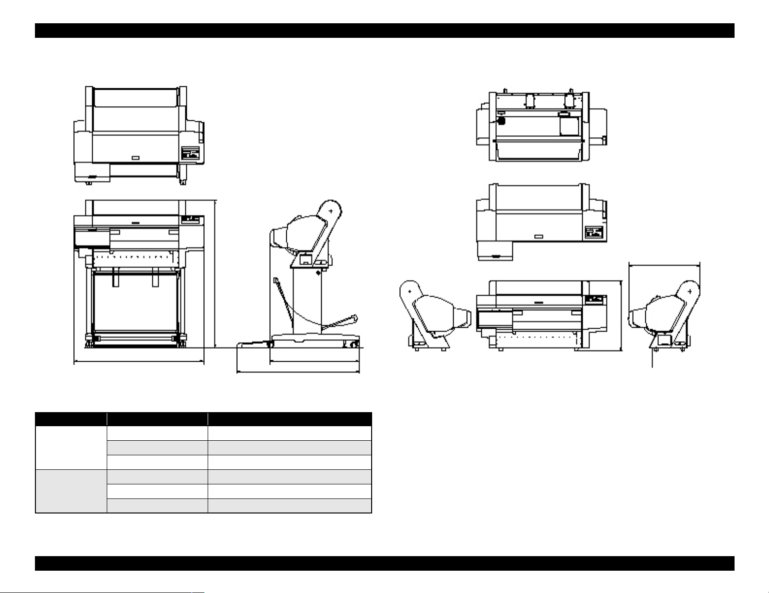
1.2.10 Overall Dimensions
604.94
1181.21
560.91
1100 754.11
1033.94
Figure 1-4. Overall Dimensions of Stylus Pro 7600
Dimensions of Unit
Model Condition Width (W) × Depth (D) × Height (H) (mm)
Stylus Pro 7600 Printer body 1100 ×805 × 561
Rearward paper eject 1100 × 754 × 1181
Frontward paper eject 1100
Stylus Pro 9600 Frontward paper eject 1624 × 691 × 1178
Rearward paper eject 1624
Frontward paper eject 1624 × 1076 × 1178
× 1034 × 1181
× 697 × 1178
Note 1: For “rearward paper eject”, the paper exit tray is brought down toward the rear.
2: For “frontward paper eject”, the paper exit tray is brought down toward the front.
Product Description Basic Specifications 26
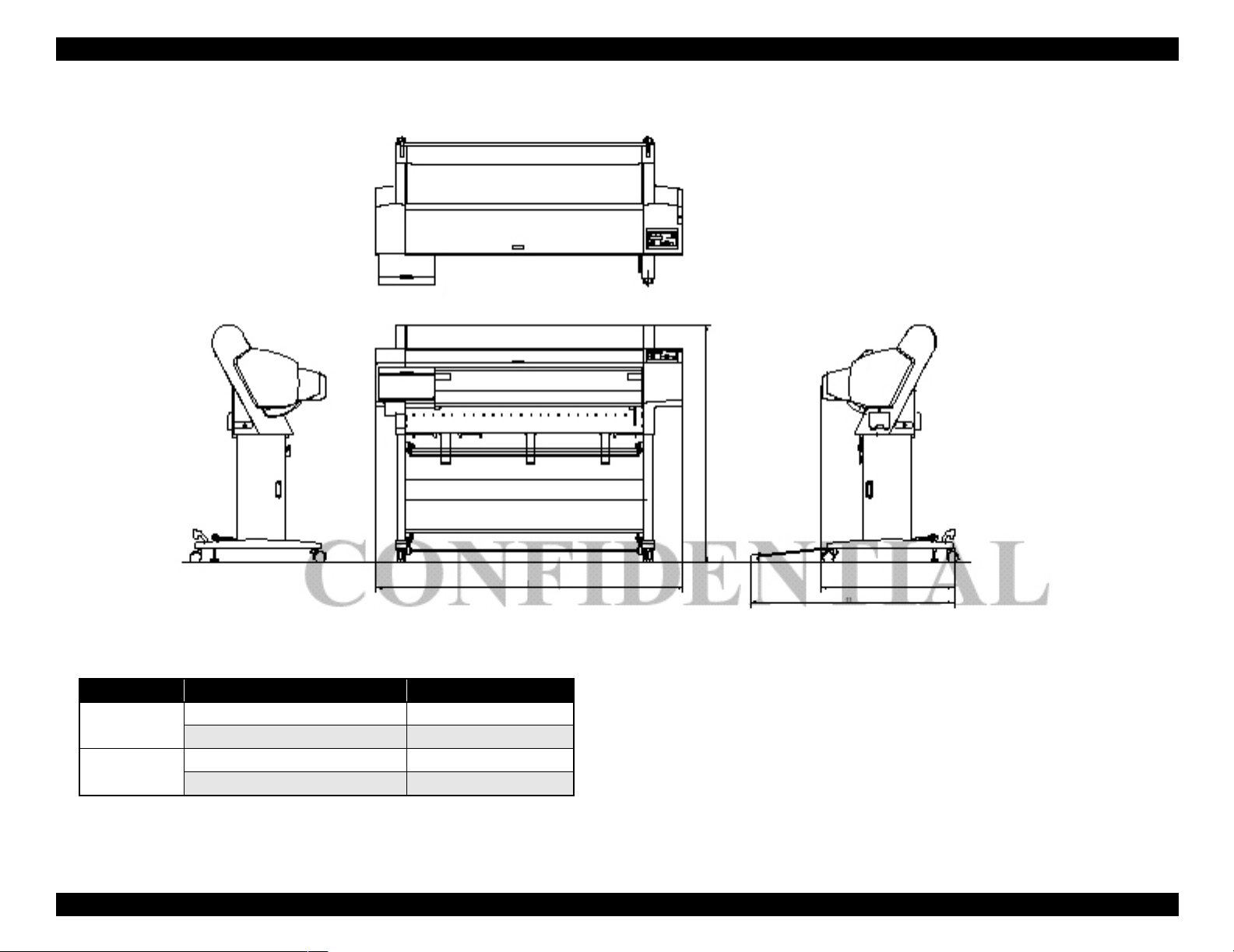
EPSON Stylus Pro 7600/9600 Revision A
1178.41
1624.1
697
1076.33
Figure 1-5. Overall Dimensions of Stylus Pro 9600
Weight
Model Condition Weight
Stylus Pro 7600 Printer body (without feet mounted) * About 43.5 kg
Feet About 10.5 kg
Stylus Pro 9600 Printer body (without feet mounted) * About 62.0 kg
Feet About 22.5 kg
Note "*": Excluding the ink cartridges
Product Description Basic Specifications 27
EPSON Stylus Pro 7600/9600 Revision A
1.2.11 Accessories
This section describes the accessories and options for Stylus Pro 7600 and Stylus Pro
9600.
1.2.11.1 Accessories and Options for Stylus Pro 7600
Standard Accessories
AC Cable
Change Plug Adapter 3pin to 2pin
24 (2/3) inch roll paper spindle
Roll paper sample
Roll paper belt
Ink cartridges (110ml PK, MK, LK, C, M, LC, LM, Y)
Maintenance Tank
User's Manual
Driver & User's Manual
EPSON GrayBalancer & EPSON Printer Service Utility
Utility Software
Guarantee Card
Card holder
Carton Box
Special Options
Special stand (PX70MCU)
Manual cutter unit 24” (PX70MCU)
Normal tension spindle 24”<2”/3”> (PX70RPSD)
Black ink replacement kit (Draining cartridge, Cleaning cartridge)
Special Consumables
Ink cartridge (110ml)
Name
Photo Black ICBK24
Matte Black ICMB24
Light Black ICGY24
Cyan ICC24
Magenta ICLC24
Light Cyan ICM24
Light Magenta ICLM24
Yellow ICY24
Note : The 220 ml ink cartridges are supported only by Stylus Pro 9600.
Model Number
110 ml (Standard Product)
Special paper (Refer to “1.2.5 Paper Specifications (p.15)” for paper type and
size)
Maintenance tank
Options Common to Other Printers
Auto cutter blade (PM90SPB)
Leo 2.13 (PRIFNW3S)
Fairbanks (PRIF14)
Product Description Basic Specifications 28
EPSON Stylus Pro 7600/9600 Revision A
1.2.11.2 Accessories and Options for Stylus Pro 9600
Standard accessories
AC Cable
Change Plug Adapter 3pin to 2pin
Special stand
44 (2/3) inch roll paper spindle
Roll paper sample
Roll paper belt
Ink cartridges (110ml PK, MK, LK, C, M, LC, LM, Y)
Maintenance Tank
User's Manual
Driver & User's Manual
EPSON GrayBalancer & EPSON Printer Service Utility
Utility Software
Guarantee Card
Card holder
Carton Box
Special Options
Manual cutter unit 44”(PX90MCU)
Normal tension spindle 44”<2”/3”> (PX90RPSD)
High tension spindle 44”<2”/3”> (PX90HSD)
Black ink replacement kit (Draining cartridge, Cleaning cartridge)
Special Consumables
Ink cartridge (110 ml/220 ml (only for pigment))
Name
Photo Black ICBK24 ICBK25
Matte Black ICMB24 ICMB25
Light Black ICGY24 ICGY25
Cyan ICC24 ICC25
Magenta ICLC24 ICLC25
Light Cyan ICM24 ICM25
Light Magenta ICLM24 ICLM25
Yellow ICY24 ICY25
Note : The 220 ml ink cartridges are supported only by Stylus Pro 9600.
110 ml (Standard Product) 220ml (Option)
Model Number
Special paper (Refer to “1.2.5 Paper Specifications (p.15)” for paper type and
size)
Maintenance tank
Options common to other printers
Auto cutter blade (PM90SPB)
Take-up roller (PMARFU1)
Leo 2.13 (PRIFNW3S)
Fairbanks (PRIF14)
*
Product Description Basic Specifications 29
EPSON Stylus Pro 7600/9600 Revision A
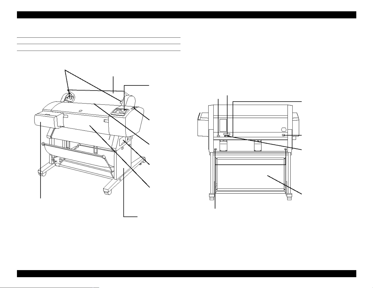
1.3 External View and Parts Names
EXTERNAL VIEW
Spindle Support
Paper Cover
Control Panel
Connector for Take-up Drive Unit
(Stylus Pro 9600 only)
Control Panel
Paper Set Lever
Connector Cover
USB Interface Connector
AC Inlet
Parallel Interface Connector
Paper Feed Slot
Maintenance Tank
Paper Receive Basket
Ink Cartridge Box
Clamp
Dedicated Stand
Stylus Pro 7600: Option
Stylus Pro 9600: Standard
Stylus Pro 7600: Option
Stylus Pro 9600: Standard
Note : Shown above is Stylus Pro 7600
Figure 1-6. External View and Parts Names
Product Description External View and Parts Names 30
Loading...