


Instruction Manual |
V500 Valve |
D100423X012 |
November 2011 |
|
|
Fisherr V500 Rotary Control Valve
Contents |
|
|
|
|
Figure 1. Fisher V500 Flanged Rotary Control Valve |
||
Introduction |
1 |
with 1061 Actuator and FIELDVUE™ DVC6200 Digital |
|
Valve Controller |
|||
Scope of Manual . . . . . . . . . . . . . . . . . . . . . . . . . . . . . |
1 |
||
Description . . . . . . . . . . . . . . . . . . . . . . . . . . . . . . . . . |
1 |
|
|
Specifications . . . . . . . . . . . . . . . . . . . . . . . . . . . . . . . |
2 |
|
|
Installation . . . . . . . . . . . . . . . . . . . . . . . . . . . . . . . . . . |
2 |
|
|
Maintenance . . . . . . . . . . . . . . . . . . . . . . . . . . . . . . . . . |
7 |
|
|
Packing Maintenance . . . . . . . . . . . . . . . . . . . . . . . . . |
8 |
|
|
Replacing Retainer, Seat Ring, and Face Seals . . . . |
10 |
|
|
Replacing Valve Plug, Shaft, and Bearings . . . . . . . |
15 |
|
|
Adjusting Actuator Travel . . . . . . . . . . . . . . . . . . . . |
20 |
|
|
Changing Valve Flow Direction . . . . . . . . . . . . . . . . |
21 |
|
|
Changing Actuator Mounting Style . . . . . . . . . . . . |
21 |
|
|
Parts Ordering . . . . . . . . . . . . . . . . . . . . . . . . . . . . . . . |
21 |
|
|
Parts Kits . . . . . . . . . . . . . . . . . . . . . . . . . . . . . . . . . . . |
22 |
|
|
Parts List . . . . . . . . . . . . . . . . . . . . . . . . . . . . . . . . . . . |
24 |
|
W8380-1
Introduction
Scope of Manual
This instruction manual provides installation, operation, maintenance, and parts ordering information for NPS 1 through 8 Fisher V500 eccentric plug rotary control valves. Refer to separate manuals for information concerning the actuator and accessories.
Do not install, operate, or maintain a V500 valve without being fully trained and qualified in valve, actuator, and accessory installation, operation, and maintenance. To avoid personal injury or property damage, it is important to carefully read, understand, and follow all the contents of this manual, including all safety cautions and warnings. If you have any questions about these instructions, contact your Emerson Process Management sales office before proceeding.
Unless otherwise noted, all NACE references are to NACE MR0175-2002.
Description
The V500 rotary control valve is a flanged (figure 1) or flangeless valve with a self-centering seat, eccentrically rotating plug, and splined valve shaft. Suitable for forward or reverse flow use, this valve mates with a variety of actuators to provide throttling or on-off service. Both flanged and flangeless valves mate with CL150, 300, or 600 raised face pipeline flanges or DIN PN10 through PN100 flanges.
www.Fisher.com

V500 Valve |
Instruction Manual |
November 2011 |
D100423X012 |
|
|
Table 1. Specifications
Valve Sizes(1)
NPS J 1, J 1-1/2, J 2, J 3, J 4, J 6, and J 8. DN 25, 40, 50, 80, 100, 150 and 200 sizes are also available.
End Connection Style
J Raised-face flanges, J ring-type joint flanges (ASME B16.5), J or flangeless valve body designed to fit between raised face flanges. J CL150, J CL300, or J CL600; (CL600 is not available in NPS 6 and 8 flangeless valve bodies). DIN PN10 through PN100 flanges also available; consult your Emerson Process Management sales office
Maximum Inlet Pressure(2)
Consistent with applicable ASME B16.34 or EN 12516-1 ratings
Shutoff Classification
Class IV per ANSI/FCI 70-2 and IEC 60534-4 (0.01% of valve capacity at full travel), for either flow direction. Leak rates for full and restricted port valves are based on full port capacities. Reduced port valves seat at the full port diameter.
Flow Characteristic
Modified linear
Flow Direction
J Reverse Flow (Standard Direction): Past valve plug and through seat ring tends to close the valve, recommended for erosive and general service
J Forward Flow: Through seat ring and past valve plug; tends to open the valve, recommended for high pressure drop and high cycle service
Actuator Mounting
J Left-hand or J right-hand as viewed from the upstream side of the valve. See figure 2
Valve Plug Rotation
Counterclockwise to close (when viewed from actuator side of valve) through 90 degrees of valve plug rotation
Valve/Actuator Action
With diaphragm or piston rotary actuator, field-reversible between J push-down-to-close (extending actuator rod closes the valve) and J push-down-to-open (extending actuator rod opens the valve)
Shaft Diameters(3) and Approximate Weights
See table 2
1.The Valve Size shown in this manual refers to Nominal Pipe Size (NPS).
2.The pressure or temperature limits in this manual and any applicable standard limitations should not be exceeded.
3.Shaft diameter and spline end must match available shaft diameter of actuator.
Installation

 WARNING
Always wear protective gloves, clothing, and eyewear when performing any maintenance operations to avoid personal injury.
To avoid personal injury or property damage resulting from the sudden release of pressure, do not install the valve assembly where service conditions could exceed the limits given on the appropriate nameplates, or the mating pipe flange rating. Use pressure-relieving devices as required by government or accepted industry codes and good engineering practices.
Check with your process or safety engineer for any other hazards that may be present from exposure to process media.
If installing into an existing application, also refer to the WARNING at the beginning of the Maintenance section in this instruction manual.
CAUTION
When ordered, the valve configuration and construction materials were selected to meet particular pressure, temperature, pressure drop, and controlled fluid conditions. Responsibility for the safety of process media and compatibility of valve
2

Instruction Manual |
V500 Valve |
D100423X012 |
November 2011 |
|
|
materials with process media rests solely with the purchaser and end-user. Since some valve body/trim material combinations are limited in their pressure drop and temperature ranges, do not apply any other conditions to the valve without first contacting your Emerson Process Management sales office.
Table 2. Shaft Diameter and Approximate Weights
|
SHAFT DIAMETER |
|
|
APPROXIMATE WEIGHT |
|
|
||||
VALVE SIZE, |
|
Flanged |
|
|
Flangeless |
|
||||
|
|
|
|
|
|
|
|
|||
Through |
|
|
|
|
|
|
|
|
|
|
NPS |
|
At Spline End |
CL150 |
CL300 |
CL600 |
CL150 |
CL300 |
CL600 |
||
Valve |
|
|||||||||
|
|
|
|
|
|
|
|
|
|
|
|
|
mm |
|
|
kg |
|
|
kg |
|
|
1 |
12.7 |
|
|
12.7 |
5.4 |
5.9 |
5.9 |
3.6 |
3.6 |
3.6 |
|
|
|
|
|
|
|
|
|
|
|
1-1/2 |
15.9 |
|
|
15.9 |
8.6 |
9.5 |
10 |
5.4 |
5.4 |
5.4 |
|
|
|
|
|
|
|
|
|
|
|
2 |
15.9 |
|
|
15.9 |
9.5 |
11 |
13 |
8.2 |
8.2 |
8.2 |
|
|
|
|
|
|
|
|
|
|
|
3 |
25.4 |
|
|
25.4 |
19 |
24 |
26 |
16 |
16 |
16 |
|
|
|
|
|||||||
25.4 |
|
|
19.1 |
|||||||
|
|
|
|
|
|
|
|
|
||
|
|
|
|
|
|
|
|
|
|
|
4 |
31.8 |
|
|
31.8 |
36 |
42 |
50 |
34 |
34 |
34 |
|
|
|
|
|
|
|
|
|
|
|
6 |
38.1 |
|
|
38.1 |
54 |
69 |
93 |
50 |
50 |
- - - |
|
|
|
|
|||||||
38.1 |
|
|
31.8 |
|||||||
|
|
|
|
|
|
|
|
|
||
|
|
|
|
|
|
|
|
|
|
|
8 |
38.1 |
|
|
38.1 |
79 |
98 |
135 |
57 |
68 |
- - - |
|
|
Inches |
|
|
lbs |
|
|
lbs |
|
|
1 |
1/2 |
|
|
1/2 |
12 |
13 |
13 |
8 |
8 |
8 |
|
|
|
|
|
|
|
|
|
|
|
1-1/2 |
5/8 |
|
|
5/8 |
19 |
21 |
23 |
12 |
12 |
12 |
|
|
|
|
|
|
|
|
|
|
|
2 |
5/8 |
|
|
5/8 |
21 |
25 |
28 |
18 |
18 |
18 |
|
|
|
|
|
|
|
|
|
|
|
3 |
1 |
|
|
1 |
42 |
52 |
57 |
35 |
35 |
35 |
|
|
|
|
|||||||
1 |
|
|
3/4 |
|||||||
|
|
|
|
|
|
|
|
|
||
|
|
|
|
|
|
|
|
|
|
|
4 |
1-1/4 |
|
|
1-1/4 |
79 |
93 |
111 |
75 |
75 |
75 |
|
|
|
|
|
|
|
|
|
|
|
6 |
1-1/2 |
|
|
1-1/2 |
120 |
152 |
204 |
110 |
110 |
- - - |
|
|
|
|
|||||||
1-1/2 |
|
|
1-1/4 |
|||||||
|
|
|
|
|
|
|
|
|
||
|
|
|
|
|
|
|
|
|
|
|
8 |
1-1/2 |
|
|
1-1/2 |
75 |
217 |
298 |
125 |
150 |
- - - |
|
|
|
|
|
|
|
|
|
|
|
Key numbers in this procedure are shown in figure 11 (NPS 1 and 1-1/2 valves) or figure 13 (NPS 2 through 8 valves) unless otherwise indicated.
CAUTION
To prevent product damage during storage, keep the valve body cavity dry and clear of foreign material.
1.If the valve is to be stored before installation, protect the flange mating surfaces and keep the valve body cavity dry and clear of foreign material.
2.Install a three-valve bypass around the control valve assembly if continuous operation will be necessary during inspection and maintenance of the valve.
3.A V500 valve is normally shipped as part of a control valve assembly, with a power or manual actuator mounted on the valve. If the valve and actuator have been purchased separately or if the actuator has been removed from the valve, mount the actuator according to the Actuator Mounting procedure. Also, adjust the actuator travel using the Adjusting Actuator Travel procedure before installing the valve. The necessary measurements cannot be made with the valve installed.
4.Before starting the actual installation of the valve, determine the proper installation orientation of the valve plug (key 2) and actuator. Determine the flow direction of the process fluid through the valve. See figure 2.
3

V500 Valve |
Instruction Manual |
November 2011 |
D100423X012 |
|
|
Figure 2. Index Marks for Actuator Lever Orientation
43A5323-D
C0586-1
4

Instruction Manual |
|
|
|
|
|
|
|
|
|
|
V500 Valve |
|
|||
D100423X012 |
|
|
|
|
|
|
|
|
|
|
|
|
November 2011 |
|
|
|
|
|
|
|
|
|
|
|
|
|
|
|
|
|
|
Table 3. Line Stud (Key 36) |
|
|
|
|
|
|
|
|
|
|
|
|
|||
|
|
|
|
|
|
|
|
|
|
|
|
|
|
|
|
|
|
|
|
|
|
|
M(1) |
|
|
|
|
|
|
||
Valve Size |
|
Pressure Rating |
|
Qty |
|
Bolt Size |
|
Bolt Length |
|
||||||
NPS |
|
|
|
|
Inches |
|
|||||||||
|
|
|
|
|
|
|
|
|
|
|
|
|
|||
|
|
|
|
CL150 |
|
4 |
|
|
5/8-11 UNC |
10.62 |
|
||||
|
|
|
|
|
|
|
|
|
|
|
|
|
|
|
|
3 |
|
|
|
CL300 |
|
6 |
|
|
3/4-10 UNC |
11.12 |
|
||||
|
|
|
|
|
|
|
|
|
|
|
|
|
|
|
|
|
|
|
|
CL600 |
|
6 |
|
|
3/4-10 UNC |
11.50 |
|
||||
|
|
|
|
|
|
|
|
|
|
|
|
|
|
|
|
|
|
|
|
CL150 |
|
6 |
|
|
5/8-11 UNC |
11.44 |
|
||||
|
|
|
|
|
|
|
|
|
|
|
|
|
|
|
|
4 |
|
|
|
CL300 |
|
6 |
|
|
3/4-10 UNC |
12.12 |
|
||||
|
|
|
|
|
|
|
|
|
|
|
|
|
|
|
|
|
|
|
|
CL600 |
|
6 |
|
|
7/8- 9 UNC |
13.62 |
|
||||
|
|
|
|
|
|
|
|
|
|
|
|
|
|
|
|
6 |
|
|
|
CL150 |
|
5 |
|
|
3/4-10 UNC |
13.62 |
|
||||
|
|
|
|
|
|
|
|
|
|
|
|
|
|
|
|
|
|
CL300 |
|
6 |
|
|
3/4-10 UNC |
14.38 |
|
||||||
|
|
|
|
|
|
|
|
||||||||
|
|
|
|
|
|
|
|
|
|
|
|
|
|
|
|
8 |
|
|
|
CL150 |
|
8 |
|
|
3/4-10 UNC |
13.62 |
|
||||
|
|
|
|
|
|
|
|
|
|
|
|
|
|
|
|
|
|
CL300 |
|
10 |
|
|
7/8- 9 UNC |
15.38 |
|
||||||
|
|
|
|
|
|
|
|
||||||||
|
|
|
|
|
|
|
|
|
|
|
|
|
|
|
|
1. These bolts may be installed from either end of the valve. |
|
|
|
|
|
|
|
|
|
||||||
|
|
|
|
|
|
|
|
|
|
|
|
|
|
|
|
Table 4. Line Stud (Key 36)(1) |
|
|
|
|
|
|
|
|
|
|
|
|
|||
|
|
|
|
|
|
|
R |
|
|
|
|
|
|
||
Valve Size |
|
Pressure Rating |
|
Qty |
|
|
Bolt Size |
|
|
Bolt Length |
|
||||
NPS |
|
|
|
|
|
|
Inches |
|
|||||||
|
|
|
|
|
|
|
|
|
|
|
|
|
|||
6 |
|
|
|
CL150 |
|
6 |
|
|
3/4-10 UNC |
|
5.00 |
|
|||
|
|
|
|
|
|
|
|
|
|
|
|
|
|
|
|
|
|
CL300 |
|
6 |
|
|
3/4-10 UNC |
|
5.00 |
|
|||||
|
|
|
|
|
|
|
|
|
|||||||
|
|
|
|
|
|
|
|
|
|
|
|
|
|
|
|
8 |
|
|
|
CL150 |
|
- - - |
|
|
- - - |
|
|
- - - |
|
||
|
|
|
|
|
|
|
|
|
|
|
|
|
|
|
|
|
|
CL300 |
|
4 |
|
|
7/8- 9 UNC |
|
5.62 |
|
|||||
|
|
|
|
|
|
|
|
|
|||||||
|
|
|
|
|
|
|
|
|
|
|
|
|
|
|
|
1. Use instead of cap screws. |
|
|
|
|
|
|
|
|
|
|
|
|
|
|
|
|
|
|
|
|
|
|
|
|
|
|
|
|
|
|
|
Table 5. Cap Screw (Key 37) |
|
|
|
|
|
|
|
|
|
|
|
|
|||
|
|
|
|
|
|
|
|
|
|
|
|
|
|
|
|
|
|
|
|
|
|
N |
|
|
|
|
|
|
|
P |
|
Valve Size |
|
Pressure Rating |
|
Qty |
Bolt Size |
|
Bolt Length |
|
Overall Length |
|
|||||
NPS |
|
|
|
Inches |
|
Inches |
|
||||||||
|
|
|
|
|
|
|
|
|
|
|
|
||||
|
|
|
CL150 |
|
- - - |
|
- - - |
|
- - - |
|
|
- - - |
|
||
|
|
|
|
|
|
|
|
|
|
|
|
|
|
||
3 |
|
|
CL300 |
|
4 |
|
3/4-10 UNC |
|
2.38 |
|
|
2.88 |
|
||
|
|
|
CL600 |
|
4 |
|
3/4-10 UNC |
|
2.38 |
|
|
2.88 |
|
||
|
|
|
|
|
|
|
|
|
|
|
|
|
|
||
|
|
|
CL150 |
|
4 |
|
5/8-11 UNC |
|
2.00 |
|
|
2.44 |
|
||
|
|
|
|
|
|
|
|
|
|
|
|
|
|
||
4 |
|
|
CL300 |
|
4 |
|
3/4-10 UNC |
|
2.38 |
|
|
2.88 |
|
||
|
|
|
CL600 |
|
4 |
|
7/8- 9 UNC |
|
2.75 |
|
|
3.38 |
|
||
|
|
|
|
|
|
|
|
|
|
|
|
|
|
|
|
Figure 3. Line Bolt Dimensions for Flangeless Valve Bodies (also see tables 3, 4 and 5)
|
|
M |
|
LINE |
LINE STUDS |
|
STUDS |
|
|
|
|
|
1 |
CAP |
|
SCREWS |
|
|
|
|
|
R |
N |
|
P |
|
|
|
|
NOTE: |
|
|
1 |
USED INSTEAD OF CAP SCREWS |
|
A4347 |
|
|
5
V500 Valve |
|
|
|
|
|
Instruction Manual |
|
November 2011 |
|
|
|
|
|
D100423X012 |
|
|
|
|
|
|
|
|
|
|
|
|
|
|
|
|
|
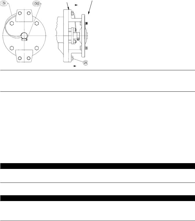
Figure 4. Optional Shaft-to-Body Bonding Strap Assembly |
|
||||||
VALVE BODY |
|
|
ACTUATOR |
|
|
|
|
|
|
|
|||||
|
|
|
A |
|
|||
|
|
|
|
||||
|
|
|
|
|
|||
|
|
|
|
|
|||
|
|
|
|
|
|
|
|
37A6528-A
A3143-2
VIEW A-A |
|
A |
|
Note
For best shutoff performance and to reduce bearing wear, it is recommended that you install the valve shaft in a horizontal direction. See figure 1.
5.Before installing the valve, make sure the flow direction arrow (key 32) on the valve matches the actual process fluid flow direction through the valve for the application where the valve will be installed.
6.Install the flange gaskets and insert the valve between the mating pipeline flanges. For flangeless valve bodies, also make sure the mating line flanges are aligned. Use flat sheet gaskets compatible with the process media, or spiral wound gaskets with compression-controlling center rings.
Ceramic Trim
Some types of ceramic trim, including the VTC (very tough ceramic) variety, can create a spark under certain circumstances. When the edge of a ceramic part is struck against a second ceramic part with enough force, a spark can be created.

 WARNING
Avoid personal injury and property damage from ignition of process fluid caused by sparks from ceramic trim. Do not use ceramic trim where the process fluid is unstable or if it is an explosive mixture (such as air and ether).

 WARNING
The valve drive shaft is not necessarily grounded to the pipeline when installed. Personal injury or property damage could result if the process fluid or the atmosphere around the valve is flammable, from an explosion caused by a discharge of static electricity from the valve components. If the valve is installed in a hazardous area, electrically bond the drive shaft to the valve.
6

Instruction Manual |
V500 Valve |
D100423X012 |
November 2011 |
|
|
1.Prepare to install the line bolts and nuts. For flangeless valves, consult figure 3 before installing the line bolts and nuts. Figure 3 shows the line bolt clearances required when installing flangeless valves.
Note
Standard PTFE packing is composed of a partially conductive carbon-filled PTFE female adaptor with PTFE V-ring packing. Standard graphite packing is composed of all conductive graphite ribbon packing rings. Alternate shaft-to-valve body bonding is available for hazardous service areas where the standard packing is not sufficient to bond the shaft to the valve (see the following step).
2.For hazardous applications, attach the bonding strap assembly (key 131) to the shaft with the clamp (key 130) and connect the other end of bonding strap assembly to the valve body with the cap screw (key 25). See figure 4.
For all valve bodies, install the line bolts and nuts; then, tighten them using accepted bolting procedures. These procedures include, but are not limited to, lubricating the line bolts and hex nuts and tightening the nuts in a crisscross sequence to ensure proper gasket load.
3.If a purge is desired for the purged bearing construction, remove the pipe plugs (keys 29 and 24) and install the purge lines. Purge pressure should be greater than the pressure within the valve and the purge fluid should be as clean as possible.
4.Connect pressure lines to the actuator as indicated in the actuator instruction manual. When a manual actuator is used with a power actuator, install a bypass valve on the power actuator (if not already supplied) for use during manual operation.

 WARNING
Personal injury could result from packing leakage. Valve packing was tightened before shipment; however, the packing might require some readjustment to meet specific service conditions. Check with your process or safety engineer for any other hazards that may be present from exposure to process media.
If the valve has ENVIRO-SEALt live-loaded packing installed readjustment will probably not be required. See the Emerson Process Management instruction manual entitled ENVIRO-SEAL Packing System for Rotary Valves, D101643X012 for packing instructions. If you wish to convert your present packing arrangement to ENVIRO-SEAL packing, refer to the retrofit kits listed in the Parts Kit section later in this manual.
Maintenance

 WARNING
Avoid personal injury or property damage from sudden release of process pressure or bursting of parts. Before performing any maintenance operations:
D Do not remove the actuator from the valve while the valve is still pressurized.
DAlways wear protective gloves, clothing and eyewear when performing any maintenance operations to avoid personal injury.
DDisconnect any operating lines providing air pressure, electric power, or a control signal to the actuator. Be sure the actuator cannot suddenly open or close the valve.
DUse bypass valves or completely shut off the process to isolate the valve from process pressure. Relieve process pressure from both sides of the valve. Drain the process media from both sides of the valve.
7

V500 Valve |
Instruction Manual |
November 2011 |
D100423X012 |
|
|
D Vent the power actuator loading pressure and relieve any actuator spring precompression.
D Use lock-out procedures to be sure that the above measures stay in effect while you work on the equipment.
DThe valve packing area may contain process fluids that are pressurized, even when the valve has been removed from the pipeline. Process fluids may spray out under pressure when removing the packing hardware or packing rings.
D Check with your process or safety engineer for any other hazards that may be present from exposure to process media.
Valve parts are subject to normal wear and must be inspected and replaced as necessary. The frequency of inspection and replacement depends upon the severity of service conditions.
As used in these instructions, the term “actuator” refers to power actuators (such as pneumatic diaphragm or piston actuators) or manual actuators (such as handwheel or handlever actuators).
Packing Maintenance
Key numbers are referenced in figures 11 and 13 unless otherwise indicated.
Note
For the ENVIRO-SEAL packing system, refer to the Parts Ordering section for retrofit kits and parts kits(see figure 14). Refer to the separate ENVIRO-SEAL instruction manual for maintenance instructions.
Standard ENVIRO-SEAL packing systems can be used in vacuum service with packing rings in the standard orientation. It is not necessary to reverse the ENVIRO-SEAL PTFE packing rings.
Stopping Leakage
All maintenance procedures in this section may be performed with the valve body (key 1) in the line.
For packing other than spring-loaded packings, leakage around the packing follower (key 14) can be stopped by tightening the packing flange nuts (key 16). If leakage cannot be stopped in this manner, replace the packing according to the Replacing Packing procedure.
If the packing is relatively new and tight on the valve shaft (key 3), and if tightening the packing nuts does not stop leakage, it is possible that the valve shaft is worn or nicked so that a seal cannot be made. If the leakage comes from the outside diameter of the packing, it is possible that the leakage is caused by nicks or scratches on the packing box wall. Inspect the shaft and packing box wall for nicks or scratches when performing the following procedures.
Replacing Packing
Note
If the valve has ENVIRO-SEAL live-loaded packing installed, see the separate ENVIRO-SEAL instruction manual.
This procedure may be performed without removing the actuator from the valve body if adding PTFE/composition packing rings as a temporary measure. However, the actuator must be removed if replacing any other kind of packing or if the metal packing parts (keys 14, 17, and, if used, 18) need to be replaced.
8

Instruction Manual |
V500 Valve |
D100423X012 |
November 2011 |
|
|
Removing the Packing
1.Isolate the control valve from the line pressure, release pressure from both sides of the valve, and drain the process media from both sides of the valve. If using a power actuator, also shut off all pressure lines to the power actuator, release all pressure from the actuator. Use lock-out procedures to be sure that the above measures stay in effect while you work on the equipment.
CAUTION
When the actuator is removed from the valve, do not use a hammer or similar tool to drive the lever or actuator off the valve shaft. Driving the lever or actuator off the valve shaft could damage the valve plug, seal, and valve.
If necessary, use a wheel puller to remove the lever or actuator from the valve shaft. It is okay to tap the wheel puller screw lightly to loosen the lever or actuator, but hitting the screw with excessive force could damage the valve plug, seal, and valve.
2.If necessary, remove the cap screws (key 25) and hex nuts (key 26). Then remove the actuator while referring to the actuator manual for assistance.
3.Remove the packing nuts (key 16) and packing follower (key 14).
4.Remove the old packing rings (key 13), packing box ring (key 17), and, if used, the lantern ring (key 18).
CAUTION
Do not scratch the valve shaft or packing box wall. Scratching these surfaces could cause leakage.
5.Clean all accessible metal parts and surfaces to remove particles that would prevent the packing from sealing.
6.If necessary, complete the steps in the Replacing the Valve Plug, Shaft, and Bearings section, and return to the Installing Packing steps below.
Installing Packing
1.Install the new packing rings and packing box ring by stacking the parts as shown in figure 5. Make sure split rings are arranged so that the splits do not line up to form a leak path. Then slide the stack into the packing box as far as will go while being careful to avoid trapping air among the rings.
2.Install the studs, packing follower, and nuts.
CAUTION
To prevent possible product damage or leakage, make sure the valve plug remains in the closed position when installing new packing parts.
3.Make sure the valve plug is in the closed position when installing new packing parts.
4.Insert a screw driver, pry bar, or similar tool between the lower ear of the plug and the valve body (see figure 6). Use the pry to move the plug tightly against the thrust washer and bearing on the actuator side of the valve. Keep the valve plug in that position until you have completed the packing installation.
5.Tighten packing flange nuts enough to stop leakage under normal conditions.
6.Mount the actuator while referring to the actuator mounting procedures of the actuator instruction manual. You must complete the Adjusting Actuator Travel procedure in this manual before installing the valve in the pipeline, due to the measurements that must be made during the actuator adjustment process.
9

V500 Valve |
Instruction Manual |
November 2011 |
D100423X012 |
|
|
7.When the control valve is being put back into operation, check the packing follower for leakage, and retighten the packing nuts as necessary.
Replacing Retainer, Seat Ring, and Face Seals
This procedure is to be performed if the control valve is not shutting off properly, if the port diameter is to be changed by installing a different seat ring, or if seat ring inspection is necessary. The actuator and valve (key 1) must be removed from the pipeline; however, the actuator may remain mounted during this procedure.
A retainer tool is required to remove the retainer (key 5), seat ring (key 4), and face seals (key 8). If specifically ordered, a tool is supplied with the valve; a tool can also be ordered individually. If desired, a tool can be machined using the dimensions shown in figure 7.
During assembly, handle the retainer, seat ring, and face seals carefully. Critical areas that must be protected are the threads and inner surface of the retainer (key 5), the sealing surfaces of the face seals (key 8), the face seal grooves in the seat ring (key 4), the shutoff surface of the seat ring, and the face seal surface in the valve body (key 1).
A new retainer gasket (key 11) is required whenever the retainer (key 5) is removed. Other parts in good condition can be reused.
Disassembly of Retainer, Seat Ring, and Face Seals
Key numbers are shown in figures 11 and 13 unless otherwise noted.
1.Isolate the control valve from the line pressure, release pressure from both sides of the valve body, and drain the process media from both sides of the valve. If using a power actuator, also shut off all pressure lines to the power actuator, release all pressure from the actuator. Use lock-out procedures to be sure that the above measures stay in effect while you work on the equipment.
2.Remove line bolting. Then, remove the control valve from the pipeline and place the valve on a flat surface with the retainer (key 5) facing up.
3.Rotate the valve shaft (key 3) to move the valve plug (key 2) into the open position.
Note
The retainer (key 5) was installed at the factory using the torque listed in figure 8.
4.Remove the retainer by engaging the retainer tool, attaching an impact wrench or other suitable tool, and unscrewing the retainer. Inspect the retainer.
CAUTION
Place the retainer on a protected, flat surface where the threads and inner surface will not be contaminated or damaged.
5.Remove the retainer gasket (key 11). Inspect the gasket surfaces on the valve body (key 1).
6.Lift out the seat ring (key 4) and both face seals (key 8). Inspect the parts and place them on a flat, protected surface.
7.Inspect the shutoff surface of the valve plug. If it is worn, nicked, or scratched, proceed to the Replacing Valve Plug, Shaft, and Bearings procedure. If the parts are in good shape and do not require maintenance, continue to the Assembly procedure.
10
 Loading...