


Instruction Manual |
V250 Valve |
D100422X012 |
September 2013 |
|
|
Fisherr V250 Ball Valve
Contents |
|
Introduction . . . . . . . . . . . . . . . . . . . . . . . . . . . . . . . . . |
1 |
Scope of Manual . . . . . . . . . . . . . . . . . . . . . . . . . . . . . |
1 |
Description . . . . . . . . . . . . . . . . . . . . . . . . . . . . . . . . . |
1 |
Installation . . . . . . . . . . . . . . . . . . . . . . . . . . . . . . . . . . |
3 |
Maintenance . . . . . . . . . . . . . . . . . . . . . . . . . . . . . . . . . |
6 |
Replacing the Follower Shaft Seal . . . . . . . . . . . . . . . |
6 |
Replacing the Drive Shaft Seal . . . . . . . . . . . . . . . . . |
7 |
Replacing Ball Seal or Flow Ring . . . . . . . . . . . . . . . . |
8 |
Removal . . . . . . . . . . . . . . . . . . . . . . . . . . . . . . . . |
8 |
Installation of Single or Dual Ball Seal . . . . . . . |
10 |
Installation of Flow Ring . . . . . . . . . . . . . . . . . . |
10 |
Installing Live-Loaded PTFE Packing . . . . . . . . . . . . |
11 |
Replacing Drive Shaft, Follower Shaft Ball, |
|
Bushings, and Valve Outlet Gasket . . . . . . . . . . |
12 |
Disassembly . . . . . . . . . . . . . . . . . . . . . . . . . . . . |
12 |
Assembly . . . . . . . . . . . . . . . . . . . . . . . . . . . . . . |
15 |
Actuator Mounting . . . . . . . . . . . . . . . . . . . . . . . . . . . |
19 |
Travel Adjustment . . . . . . . . . . . . . . . . . . . . . . . . . . |
19 |
Parts Ordering . . . . . . . . . . . . . . . . . . . . . . . . . . . . . . . |
19 |
Parts List . . . . . . . . . . . . . . . . . . . . . . . . . . . . . . . . . . . |
23 |
Figure 1. Fisher V250 Ball Valve with 1061 Actuator
W3698
Introduction
Scope of Manual
This instruction manual provides installation, maintenance, and parts ordering information for NPS 4 through 24 Fisher V250 valves (figure 1) that mate with ASME flanges. Other instruction manuals provide information covering the actuator and accessories.
Do not install, operate, or maintain a V250 valve without being fully trained and qualified in valve, actuator, and accessory installation, operation, and maintenance. To avoid personal injury or property damage, it is important to carefully read, understand, and follow all the contents of this manual, including all safety cautions and warnings. If you have any questions about these instructions, contact your Emerson Process Management sales office before proceeding.
Description
The V250 valve is a flangeless rotary control valve used for high pressure, throttling or on-off control of liquid or gas applications (see figure 1). These valves operate on a rotary motion input through a splined valve-shaft/actuator-shaft connection for use with power or manual handwheel actuators. The single seal, dual seal, and flow ring constructions are covered in this instruction manual.
www.Fisher.com

V250 Valve |
Instruction Manual |
September 2013 |
D100422X012 |
|
|
Table 1. Specifications
Valve Sizes and End Connection Styles
NPS 4 through 24 flangeless valves retained by line flange bolts and designed to fit between ASME raised-face or ring-type joint flanges. See table 2 for valves that install between ASME flanges
Maximum Inlet Pressure(1)
Consistent with applicable pressure-temperature ratings listed in table 2
Maximum Allowable Shutoff Pressure Drop(1,2,3)
Single-Seal and Dual-Seal Construction:
155 bar (2250 psi) at 38_C (100_F) and 103 bar (1500 psi) at 82_C (180_F) except where further limited by the pressure-temperature rating of the valve body
Flow Ring Construction: Limited by the pressure-temperature rating of the valve body
Seal Material Temperature Capability(1)
Single-Seal and Dual-Seal Construction:
-46 to 82_C (-50 to 180_F) with LCC or stainless steel valve bodies
Flow Ring Construction with Nitrile O-Rings: -46 to 93_C (-50 to 200_F) with LCC steel and stainless steel valve bodies
Flow Ring Construction with Fluorocarbon O-Rings: -46 to 204_C (-50 to 400_F) with LCC steel and stainless steel valve bodies
Flow Characteristic
Modified equal percentage
Flow Direction
Forward Flow: Single seal construction is standard for forward flow (see figure 4)
Bidirectional Flow: Flow ring construction can be used for either forward or reverse flow
(see figure 5)
Bidirectional Shutoff: Dual seal construction is required to provide shutoff for bidirectional flow (see figure 12)
Shutoff Classification
Single Seal and Dual Seal Constructions: 0.0001% of maximum valve capacity (less than 1% of Class IV, ANSI/FCI 70-2)
Flow Ring Construction: 1% of maximum valve capacity
Maximum Ball Rotation
90 degrees
Actuator Mounting
Right-hand or left-hand mounted as viewed from the valve body inlet for forward flow
Approximate Weights
See table 3
1.The pressure/temperature limits in this manual and any applicable standard or code limitation for valve should not be exceeded.
2.Maximum allowable shutoff pressure drops are further limited for the following constructions. The NPS 12 with S20910 drive shaft is limited to 128 bar (1862 psi) from -46 to 59_C
(-50 to 139_F) and to 103 bar (1490 psi) at 93_C (200_F). The NPS 16 with 17-4PH steel, with 2-1/2 inch splined drive shaft is limited to 69 bar (1000 psi), and with the S20910, 2-1/2 inch splined drive shaft is limited to 55 bar (795 psi) at all service temperatures. The NPS 24 with S20910 drive shaft is limited to 92 bar (1336 psi) at all service temperatures.
3. NPS 20 CL900 and NPS 24 CL900 flow ring is limited to 1500 psi.
Table 2. Pressure Rating and Flange Compatibility
Valve Size, NPS |
Inlet Pressure Capability |
ASME Flange Compatibility |
|
4 |
|
|
|
|
|
|
|
6 |
|
|
|
|
|
|
|
8 |
Consistent with CL600 or 900 (ASME B16.34) |
CL600 or 900 raised face or ring-type joint flange (ASME B16.5) |
|
|
|
|
|
10 |
|
|
|
|
|
|
|
12 |
|
|
|
|
|
|
|
16 |
Consistent with CL600 (ASME B16.34) |
CL600 raised face or ring-type joint flange (ASME B16.5) |
|
|
|
|
|
20 |
Consistent with CL600 or 900 (ASME B16.34) |
CL600 or 900 raised face or ring-type joint flange (ASME B16.5) |
|
|
|||
24 |
|||
|
|
||
|
|
|
2

Instruction Manual |
|
|
V250 Valve |
D100422X012 |
|
|
September 2013 |
|
|
|
|
Table 3. Approximate Weights |
|
|
|
|
|
|
|
VALVE SIZE, NPS |
|
WEIGHT |
|
Kilograms |
|
Pounds |
|
|
|
||
4 |
73 |
|
160 |
|
|
|
|
6 |
132 |
|
290 |
|
|
|
|
8 |
222 |
|
490 |
|
|
|
|
10 |
345 |
|
760 |
|
|
|
|
12 |
431 |
|
950 |
|
|
|
|
16 |
771 |
|
1700 |
|
|
|
|
20 (CL600) |
1814 |
|
4000 |
|
|
|
|
20 (CL900) |
2045 |
|
4500 |
|
|
|
|
24 |
2404 |
|
5300 |
|
|
|
|
Installation

 WARNING
Always wear protective gloves, clothing, and eyewear when performing any installation operations to avoid personal injury.
To avoid personal injury or property damage resulting from the sudden release of pressure, do not install the valve assembly where service conditions could exceed the limits given on the valve and actuator nameplates. Use pressure-relieving devices as required by accepted industry, local, state, or federal codes, and good engineering practices.
Check with your process or safety engineer for any additional measures that must be taken to protect against process media.
If installing into an existing application, also refer to the WARNING at the beginning of the Maintenance section in this instruction manual.

 WARNING
Avoid personal injury or property damage caused by uncontrolled movement or dropping of the valve assembly.
Hoist rings are sized to lift only the valve and actuator. Do not use hoist rings to lift the valve if piping or other structures are added.
Rig the lift to use two hoist rings and take appropriate precautions to avoid unbalanced loading which may result in sudden swinging or movement of the assembled unit, including additional lifting and/or support methods when necessary.
Failure to utilize safe lifting practices may result in equipment damage and/or personal injury.
1.If the valve will be placed in storage prior to installation, protect the flanges and keep the inside of the valve dry and clear of foreign material.
2.Install a three-valve bypass around the control valve assembly if continuous operation will be necessary during inspection and maintenance of the valve.
3.Inspect the valve body for damage and be certain that the valve body cavity is free of foreign material.
4.Be certain that adjacent pipelines are free of any foreign material, such as pipe scale or welding slag, that could damage the valve body seating surfaces.
5.A V250 valve is normally shipped as part of a control valve assembly, with a power or manual handwheel actuator mounted on the valve. If the valve and actuator have been purchased separately or if the actuator has been
3

V250 Valve |
Instruction Manual |
September 2013 |
D100422X012 |
|
|
removed for maintenance, mount the actuator according to the actuator mounting procedure and adjust actuator travel before inserting the valve into the pipeline. This allows necessary measurements to be made during the actuator adjustment process.
The actuator can be either right-or left-hand mounted, as viewed from the valve body inlet, in any of the positions shown in figure 10. Refer to the Actuator Mounting procedure in this manual and to the actuator instruction manual for mounting and adjusting instructions before proceeding.
6.Before installing the valve, make sure the flow through the valve matches the flow direction arrow on the valve. Failure to do so can damage the seal in a valve with a single seal construction.
D For bidirectional flow, install the valve so the highest pressure flow matches the flow direction arrow on the valve.
DInstall the V250 valve in any position, but the recommended orientation is in a horizontal pipeline with the shaft positioned horizontally and the ball closing in the downward direction.
CAUTION
To avoid damage to the ball sealing surface, rotate the ball to the fully open position before installing the valve between the pipeline flanges.
7.With the ball in the fully open position, install line flange gaskets and insert the valve between the pipeline flanges. Use standard composition gaskets, or other flat sheet gaskets compatible with the flow media, between the valve and the pipeline flanges. Spiral wound gaskets without compression controlling centering rings are not recommended.
CAUTION
Uneven tightening of line bolts may cause uneven wear of the ball surface, leakage downstream or to atmosphere, or uneven flange gasket alignment. Tighten line bolts evenly when installing the valve.
8.Center the valve in the line by making sure the mating flanges are aligned. Secure the valve in the line with the cap screws (keys 33 and 34, figures 11 and 12), line bolts (key 35, not shown), and hex nuts (key 44, not shown). Required clearances for installation of the line bolts and cap screws are shown in figure 2. When tightening the cap screws and line bolts, use accepted bolting procedures. Lubricate the studs or bolts and tighten the nuts in a crisscross sequence to ensure proper alignment of the valve with the flanges.
9.For hazardous atmosphere or oxygen service valves, read the following WARNING, and perform the instruction provided in the WARNING and provide the bonding strap assembly mentioned in Step 10 below if the valve is used in a hazardous application.

 WARNING
The V250 is not necessarily grounded to the pipeline when installed. If the process fluid or the atmosphere around the valve is flammable, personal injury or property damage could result from an explosion caused by a discharge of static electricity from the valve components. If the valve is installed in a hazardous area, electrically bond the drive shaft to the valve.
Note
The packing is composed of all conductive packing rings (graphite ribbon packing) to electrically bond the shaft to the valve for hazardous area service or non-conductive PTFE packing rings. For oxygen service applications, perform the following step.
4

Instruction Manual |
V250 Valve |
D100422X012 |
September 2013 |
|
|
Figure 2. Flange Bolt Lengths
VALVE |
|
CL600 BOLTING DIMENSIONS |
|
|
|||
Raised Face Flanges |
Ring Type Joint Flanges |
|
|||||
SIZE, NPS |
|
||||||
|
P |
N |
M(1) |
P |
N |
M(1) |
|
|
|
|
mm |
|
|
|
|
4 |
--- |
--- |
343 |
--- |
--- |
343 |
|
|
|
|
|
|
|
|
|
6 |
118 |
118 |
413 |
124 |
124 |
413 |
|
|
|
|
|
|
|
|
|
8 |
140 |
137 |
445 |
143 |
140 |
451 |
|
|
|
|
|
|
|
|
|
10 |
159 |
162 |
527 |
165 |
165 |
527 |
|
|
|
|
|
|
|
|
|
12 |
178 |
152 |
584 |
178 |
165 |
584 |
|
|
|
|
|
|
|
|
|
16 |
197 |
197 |
660 |
203 |
203 |
673 |
|
|
|
|
|
|
|
|
|
20 |
254 |
254 |
--- |
254 |
254 |
--- |
|
|
|
|
|
|
|
|
|
24 |
330 |
330 |
--- |
343 |
343 |
--- |
|
|
|
|
|
|
|
|
|
|
|
|
Inch |
|
|
|
|
4 |
--- |
--- |
13.50 |
--- |
--- |
14.50 |
|
|
|
|
|
|
|
|
|
6 |
4.63 |
4.63 |
16.25 |
4.88 |
4.88 |
16.25 |
|
|
|
|
|
|
|
|
|
8 |
5.50 |
5.38 |
17.50 |
5.63 |
5.50 |
17.75 |
|
|
|
|
|
|
|
|
|
10 |
6.25 |
6.38 |
20.75 |
6.50 |
6.50 |
20.75 |
|
|
|
|
|
|
|
|
|
12 |
7.00 |
6.00 |
23.00 |
7.00 |
6.50 |
23.00 |
|
|
|
|
|
|
|
|
|
16 |
7.75 |
7.75 |
26.00 |
8.00 |
8.00 |
26.50 |
|
|
|
|
|
|
|
|
|
20 |
10.00 |
10.00 |
--- |
10.00 |
10.00 |
--- |
|
|
|
|
|
|
|
|
|
24 |
13.00 |
13.00 |
--- |
13.50 |
13.50 |
--- |
|
|
|
|
|
|
|
|
|
1. These bolts may be installed from either end of the valve.
VALVE |
|
CL900 BOLTING DIMENSIONS |
|
|
|||
Raised Face Flanges |
Ring Type Joint Flanges |
|
|||||
SIZE, NPS |
|
||||||
|
P |
N |
M(1) |
P |
N |
M(1) |
|
|
|
|
mm |
|
|
|
|
4 |
124 |
124 |
375 |
124 |
130 |
375 |
|
|
|
|
|
|
|
|
|
6 |
127 |
127 |
445 |
127 |
133 |
445 |
|
|
|
|
|
|
|
|
|
8 |
152 |
149 |
483 |
152 |
156 |
483 |
|
|
|
|
|
|
|
|
|
10 |
168 |
171 |
546 |
168 |
175 |
546 |
|
|
|
|
|
|
|
|
|
12 |
184 |
168 |
610 |
184 |
191 |
610 |
|
|
|
|
|
|
|
|
|
20(2) |
--- |
--- |
420 |
--- |
--- |
420 |
|
|
|
|
Inch |
|
|
|
|
4 |
4.88 |
4.88 |
14.75 |
4.88 |
5.13 |
14.75 |
|
|
|
|
|
|
|
|
|
6 |
5.00 |
5.00 |
17.50 |
5.00 |
5.25 |
17.50 |
|
|
|
|
|
|
|
|
|
8 |
6.00 |
5.88 |
19.00 |
6.00 |
6.13 |
19.00 |
|
|
|
|
|
|
|
|
|
10 |
6.63 |
6.75 |
21.5 |
6.63 |
6.88 |
21.50 |
|
|
|
|
|
|
|
|
|
12 |
7.25 |
6.63 |
24 |
7.25 |
7.50 |
24.00 |
|
|
|
|
|
|
|
|
|
20(2) |
--- |
--- |
16.5 |
--- |
--- |
16.5 |
|
1. These bolts may be installed from either end of the valve.
2. For NPS 20 size, only studs and nuts are used. See the M dimension.
39A1060-A
A3140-1
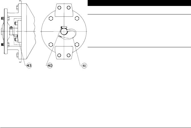
10.Attach the bonding strap assembly (key 41, figure 3) to the shaft with the clamp (key 40, figure 3), and connect the other end of the bonding strap assembly to the valve with the machine screw (key 43, figure 3).
11.Connect pressure lines to the actuator as indicated in the actuator instruction manual. When a manual actuator is used with a power actuator, install a bypass valve on the power actuator (if not already supplied) for use during manual operation.
5

V250 Valve |
Instruction Manual |
September 2013 |
D100422X012 |
|
|
Maintenance
Valve parts are subject to normal wear and must be inspected and replaced as necessary. The frequency of inspection and replacement depends upon the severity of service conditions. Instructions are presented in this section for replacing the shaft seals, the ball seal or flow ring, the drive and follower shafts, the ball and bushing, and the valve outlet gasket.
Key number locations are shown in figure 11 for single seal and flow ring constructions, and in figure 12 for dual seal constructions.

 WARNING
Personal injury or property damage can result due to a sudden release of pressure or process fluid if the pipe plug (key 42, figure 12) is removed while the valve is pressurized. To avoid such injury or damage, remove the pipe plug only when the control valve is isolated from the pressure system, or provide a hand valve to control relief of internal valve pressure to avoid personal injury or property damage.
A V250 valve with a dual seal construction contains a pipe plug port (key 42, figure 12) on the underside of the valve. This port can be used to relieve internal valve pressure for testing seal integrity when in the pipeline.
If the pipe plug port is to be used for testing seal integrity when the valve is in the pipeline, the plug should be replaced with a hand valve to allow controlled relief of valve pressure during seal leak rate testing.

 WARNING
Avoid personal injury or damage to property from sudden release of pressure or uncontrolled process fluid. Before starting disassembly:
D Do not remove the actuator from the valve while the valve is still pressurized.
DAlways wear protective gloves, clothing, and eyewear when performing any maintenance operations to avoid personal injury.
DDisconnect any operating lines providing air pressure, electric power, or a control signal to the actuator. Be sure the actuator cannot suddenly open or close the valve.
DUse bypass valves or completely shut off the process to isolate the valve from process pressure. Relieve process pressure on both sides of the valve. Drain the process media from either side of the valve.
DFor dual seal valve constructions, remove pressure and drain the valve interior by removing the pipe plug (key 42).
D Vent the power actuator loading pressure.
D Use lock-out procedures to be sure that the above measures stay in effect while you work on the equipment.
DThe valve packing box may contain process fluids that are pressurized, even when the valve has been removed from the pipeline. Process fluids may spray out under pressure when removing the packing hardware or packing rings, or when loosening the packing box pipe plug.
DCheck with your process or safety engineer for any additional measures that must be taken to protect against process media.
Replacing the Follower Shaft Seal
Both the follower and drive shaft seals should be replaced at the same time. Key number locations are shown in figure 11 or 12.
6
Instruction Manual |
V250 Valve |
D100422X012 |
September 2013 |
|
|
Perform this procedure if there is leakage around the follower shaft (key 7). Such leakage is an indication that the shaft seal, which includes the seal and a backup ring, (key 16) must be replaced. The following procedure may be performed with the valve in the pipeline.
1.Isolate the control valve from the line pressure, release pressure from both sides of valve, and drain the process media from both sides of the valve. For dual seal valve constructions, remove pressure and drain the valve interior cavity. Shut off and disconnect all lines from the power actuator.

 WARNING
Refer to the WARNING at the beginning of the Maintenance section in this instruction manual.
2.Unscrew the hex nuts (key 8) and remove the seal carrier (key 3) and shaft seal (key 16). Inspect and clean all parts and sealing surfaces on the seal carrier and follower shaft (key 7). Also, inspect and replace the O-ring (key 23) if necessary.
3.Install the new backup ring and shaft seal in the seal carrier.
Figure 3. Optional Shaft-to-Body Bonding Strap Assembly
A7101
4.Align the drive pin (key 28) with the drilled hole on the inner surface of the seal carrier, replace the seal carrier, and secure it with the hex nuts (key 8). Be careful not to damage the shaft seal or O-ring during replacement of the seal carrier.
Replacing the Drive Shaft Seal
Perform this procedure if there is leakage around the drive shaft (key 6). Such leakage is an indication that the shaft seal, which includes the seal and a backup ring, (key 16) must be replaced. This procedure may be performed with the valve in the pipeline. However, the actuator must be removed from the valve.
7

V250 Valve |
Instruction Manual |
September 2013 |
D100422X012 |
|
|
Note
The valve shaft's sealing surfaces are critical in obtaining a good seal. If the valve shafts are scratched, nicked or worn, replace or repair the valve shaft before installing new shaft seals.
Both seal rings, drive end and follower end, should be replaced at the same time.
1.Isolate the control valve from the line pressure, release pressure from both sides of valve, and drain the process media from both sides of the valve. For dual seal valve constructions, remove pressure and drain the valve interior cavity. Shut off and disconnect all lines from the power actuator.

 WARNING
Refer to the WARNING at the beginning of the Maintenance section in this instruction manual.
CAUTION
When removing the actuator in the following step, use a wheel puller to separate the actuator parts from the valve shaft. Failure to do this could cause damage to the actuator parts and the drive shaft.
2.Remove the cap screws (key 29) from the actuator mounting yoke and, while referring to the actuator instruction manual for assistance, remove the actuator. For oxygen service and hazardous area applications, remove the clamp and bonding strap assembly (keys 40 and 41, figure 3).
3.Install the new backup ring and shaft seal in the seal carrier. Be sure to install the backup ring on the correct side (see figure 4).
4.Replace the seal carrier and secure it with the hex nuts (key 8). Be careful not to damage the shaft seal or O-ring during replacement of the seal carrier.
5.Mount the actuator to the valve while referring to the Actuator Mounting section of this instruction manual and to the appropriate actuator instruction manual. If appropriate, install or replace the bonding strap assembly and the clamp (key 41 and 40, figure 3).
Replacing Ball Seal or Flow Ring
Perform this procedure if the control valve is not shutting off properly (that is, leaking downstream). This procedure does not require removing the actuator from the valve. In addition to being shown in figures 11 and 12, key numbers are shown in figure 5 for the ball seal constructions and in figure 6 for the flow ring construction.
Removal
1.Isolate the control valve from the line pressure, release pressure from both sides of valve, and drain the process media from both sides of the valve. For dual seal valve constructions, remove pressure and drain the valve interior cavity. Shut off and disconnect all lines from the power actuator.

 WARNING
Refer to the WARNING at the beginning of the Maintenance section in this instruction manual.
8
 Loading...