


Service Manual
19” LCD Monitor
DELL E193FPc
THESE DOCUMENTS ARE FOR REPAIR SERVICE INFORMATION ONLY.EVERY REASONABLE EFFORT HAS BEEN MADE TO ENSURE THE ACCURACY OF THIS MANUAL; WE CANNOT GUARANTEE THE ACCURACY OFTHIS INFORMATION AFTER THE DATE OF PUBLICATION AND DISCLAIMS RELIABILITY FOR CHANGES, ERRORS OR OMISSIONS.

|
|
Dell E193FPc |
|
Table of contents |
|
Table of contents ---------------------------------------------------------------------------------------------------------------- |
02 |
|
Revision List ----------------------------------------------------------------------------------------------------------------------------- |
03 |
|
Important Safety Notice ------------------------------------------------------------------------------------------------------------ |
04 |
|
1. Monitor Specifications ------------------------------------------------------------------------------------------------------ |
05 |
|
2. LCD Monitor Description -------------------------------------------------------------------------------------------------- |
05 |
|
3. Operation instructions----------------------------------------------------------------------------------------------------------- |
06 |
|
3.1 General Instructions--------------------------------------------------------------------------------------------------------- |
06 |
|
3.2 Control buttons ----------------------------------------------------------------------------------------------------------------- |
06 |
|
3.3 Adjusting the Picture -------------------------------------------------------------------------------------------------------- |
07 |
|
4. Input/Output Specification --------------------------------------------------------------------------------------------------- |
10 |
|
4.1 Input Signal Connector ----------------------------------------------------------------------------------------------------- |
10 |
|
4.2 Factory Preset Display Modes ----------------------------------------------------------------------------------------- |
10 |
|
4.3 Power Supply Requirements ---------------------------------------------------------------------------------------- |
11 |
|
4.4 |
Panel Specification ----------------------------------------------------------------------------------------------------- |
11 |
5. Block Diagram ---------------------------------------------------------------------------------------------------------------- |
14 |
|
5.1 |
Monitor Exploded View -------------------------------------------------------------------------------------------------------- |
14 |
5.2 |
Software Flow Chart ---------------------------------------------------------------------------------------------------- |
15 |
5.3 |
Electrical Block Diagram ---------------------------------------------------------------------------------------------- |
17 |
6. Mechanical Instruction ----------------------------------------------------------------------------------------------------------- |
19 |
|
7. Schematic -------------------------------------------------------------------------------------------------------------------------- |
24 |
|
6.1 |
Main Board --------------------------------------------------------------------------------------------------------------- |
24 |
6.2 |
Power Board --------------------------------------------------------------------------------------------------------------- |
29 |
8. Layout ----------------------------------------------------------------------------------------------------------------------- |
31 |
|
7.1 |
Main Board ---------------------------------------------------------------------------------------------------------------- |
31 |
7.2 |
Power Board -------------------------------------------------------------------------------------------------------------- |
34 |
7.3 |
Key Board ----------------------------------------------------------------------------------------------------------------- |
35 |
9. Maintainability-------------------------------------------------------------------------------------------------------------------- |
36 |
|
8.1 |
Equipments and Tools Requirement -------------------------------------------------------------------------------- |
36 |
8.2 |
Trouble Shooting --------------------------------------------------------------------------------------------------------------- |
37 |
8.2.1 Main Board---------------------------------------------------------------------------------------------------------------- |
37 |
|
8.2.2 Power/Inverter Board -------------------------------------------------------------------------------------------- |
40 |
|
8.2.3 Keypad Board ---------------------------------------------------------------------------------------------------- |
42 |
|
10. White Balance Adjustment ---------------------------------------------------------------------------------------------- |
43 |
|
11. EDID Content --------------------------------------------------------------------------------------------------------------- |
44 |
|
12. ISP User Manual ---------------------------------------------------------------------------------------------------------- |
45 |
|
11.1 Connect ISP Writer preparation action ---------------------------------------------------------------------- |
45 |
|
11.2 To Use ISP Writer ------------------------------------------------------------------------------------------------ |
46 |
|
11.3 Executing ISP ------------------------------------------------------------------------------------------------------------- |
50 |
|
13. BOM List ----------------------------------------------------------------------------------------------------------------------------- |
51 |
|
14. Definition Of Pixel Defects-------------------------------------------------------------------------------------------------------- |
74 |
|
2
|
|
|
Dell E193FPc |
|
|
|
Revision List |
|
|
|
|
|
|
|
Revision |
Date |
Revision History |
TPV model |
|
|
|
|
|
|
A00 |
Mar-15-2004 |
Initial Release |
T980KLLHJ8DMN |
|
|
|
|
|
|
A01 |
Jul-20-2005 |
Change the panel from LG (LPL 19" (B4KB)) to |
T980KSLHM8DLN |
|
SEC (SEC 19" EX1 (LOO)) |
||||
|
||||
|
|
|
|
|
A02 |
Nov-22-2005 |
Add “Important Safety Notice” |
|
|
|
|
|
|
|
A03 |
Mar.-28-2006 |
Add “Definition Of Pixel Defects” |
|
|
|
|
|
|
|
A04 |
April-25-2006 |
Add ”Max Brightness measurement” on |
|
|
Page43 |
|
|||
|
|
|
||
|
|
|
|
|
A05 |
Jun-28-2006 |
Add new model in Item 13 |
T980KALHK8DLN |
|
T980KSLHK8DLN |
||||
|
|
|
||
|
|
|
|
|
A06 |
Mar-02-2007 |
Add Mechanical Instruction in Item 6 |
|
|
|
|
|
|
|
|
|
|
|
|
|
|
|
|
|
|
|
|
|
|
|
|
|
|
|
|
|
|
|
|
|
|
|
|
|
|
|
|
|
|
|
|
|
|
|
|
|
|
|
|
|
|
|
|
|
|
|
|
|
|
|
|
|
|
|
|
|
|
|
|
|
|
|
|
|
|
|
|
|
3

Dell E193FPc
Important Safety Notice
ANY PERSON ATTEMPTING TO SERVICE THIS CHASSIS MUST FAMILIARIZE HIMSELF WITH THE CHASSIS AND BE AWARE OF THE NECESSARY SAFETY PRECAUTIONS TO BE USED WHEN SERVICING ELECTRONIC EQUIPMENT CONTAINING HIGH VOLTAGES.
CAUTION: USE A SEPARATE ISOLATION TRANSFORMER FOR THIS UNIT WHEN SERVICING REFER TO BACK COVER FOR IMPORTANT SAFETY GUIDELINGS
Important Safety Notice
Proper service and repair is important to the safe, reliable operation of all Dell Company** Equipment. The service procedures recommended by Dell and described in this service manual are effective methods of performing service operations. Some of these service operations require the use of tools specially designed for the purpose. The special tools should be used when and as recommended.
It is important to note that this manual contains various CAUTIONS and NOTICES which should be carefully read in order to minimize the risk of personal injury to service personnel. The possibility exists that improper service methods may damage the equipment. It is also important to understand that these CAUTIONS and NOTICES ARE NOT EXHAUSTIVE. Dell could not possibly know, evaluate and advise the service trade of all conceivable ways in which service might be done or of the possible hazardous consequences of each way. Consequently, Dell has not undertaken any such broad evaluation. Accordingly, a servicer who uses a service procedure or tool which is not recommended by Dell must first satisfy himself thoroughly that neither his safety nor the safe operation of the equipment will be jeopardized by the service method selected.
* * Hereafter throughout this manual, Dell Company will be referred to as Dell. WARNING
Use of substitute replacement parts, which do not have the same, specified safety characteristics may create shock, fire, or other hazards.
Under no circumstances should the original design be modified or altered without written permission from Dell. Dell assumes no liability, express or implied, arising out of any unauthorized modification of design. Servicer assumes all liability.
FOR PRODUCTS CONTAINING LASER:
DANGER - Invisible laser radiation when open. AVOID DIRECT EXPOSURE TO BEAM. CAUTION - Use of controls or adjustments or performance of procedures other than those
specified herein may result in hazardous radiation exposure.
CAUTION - The use of optical instruments with this product will increase eye hazard.
TO ENSURE THE CONTINUED RELIABILITY OF THIS PRODUCT, USE ONLY ORIGINAL MANUFACTURER'S REPLACEMENT PARTS, WHICH ARE LISTED WITH THEIR PART NUMBERS IN THE PARTS LIST SECTION OF THIS SERVICE MANUAL.
Take care during handling the LCD module with backlight unit
-Must mount the module using mounting holes arranged in four corners.
-Do not press on the panel, edge of the frame strongly or electric shock as this will result in damage to the screen.
-Do not scratch or press on the panel with any sharp objects, such as pencil or pen as this may result in damage to the Panel.
-Protect the module from the ESD as it may damage the electronic circuit (C-MOS).
-Make certain that treatment person’s body is grounded through wristband.
-Do not leave the module in high temperature and in areas of high humidity for a long time.
-Avoid contact with water as it may a short circuit within the module.
If the surface of panel becomes dirty, please wipe it off with a soft material. (Cleaning with a dirty or rough cloth may damage the panel.)
4

Dell E193FPc
1. Monitor Specifications
48 cm (19”) a-si TFT Active matrix LCD panel, 0.294mm dot pitch. 16 factory presets, 20 new modes
Vertical refresh rate 55Hz to 75 Hz Horizontal frequency 30kHz to 80kHz Resolutions: 640 x 480 up to 1280 x 1024
Universal power supply designed for worldwide application CE mark
TCO-99
VESA DPMS compliant VESA DDC compliant
2. LCD Monitor Description
The LCD MONITOR will contain a main board, PWPC board, keypad board, which house the flat panel control logic, brightness control logic and DDC.
The power board will provide AC to DC Inverter voltage to drive the backlight of panel and the main board chips each voltage.
Monitor Block Diagram
|
CCFL Drive. |
|
|
|
Flat Panel and |
|
|
|
|||
|
|
|
|
|
|
|
CCFL backlight |
|
|
|
|
|
|
|
|
|
|
|
|
|
|
||
|
|
|
|
|
|
|
|
|
|
|
|
|
|
|
|
|
|
|
|
|
|
|
|
|
|
|
|
|
|
|
|
|
|
|
RS232 Connector |
PWPC board |
|
|
Main Board |
|
|||||||
|
|
|
|
For white balance |
|||||||
(Include adapter and Inverter |
|
|
|
|
|
|
|
|
|
||
|
|
|
|
|
|
|
|
|
adjustment in factory |
||
board) |
|
|
|
|
|
|
|
|
|
||
|
|
|
|
|
|
|
|
|
mode |
||
|
|
|
|
|
|
|
|
|
|
|
|
|
|
|
|
Keyboard |
|
|
|
|
|||
|
|
|
|
|
|
|
|
||||
|
|
|
|
|
|
Video signal, DDC |
|||||
|
|
|
|
|
|
|
|||||
|
|
|
|
|
|
|
|||||
|
|
|
|
|
|
|
|
|
|||
AC-IN |
|
|
|
Host Computer |
|
|
|||||
|
|
|
|
|
|
|
|
||||
|
|
|
|
|
|
|
|
||||
100-240V |
|
|
|
|
|
|
|
|
|||
5
Dell E193FPc
3.Operation instructions
3.1General Instructions
Press the power button to turn the monitor on or off. The other control buttons are located at front panel of the monitor. By changing these settings, the picture can be adjusted to your personal preferences.
-The power cord should be connected.
-Connect the video cable from the monitor to the video card.
-Press the power button to turn on the monitor, the power indicator will light up.
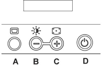
3.2 Control Buttons
Power Button: When pressed, the monitor enters the off mode, and the LED turns blank. Press again to restore normal status.
Brightness Button: The Brightness Button is used to select the Brightness/Contrast adjust functions. Press to switch functions or adjust settings.
Auto Adjust Key: The Auto Adjust Key is used to automatically set the H Position, V Position, Clock and Phase.
Power Indicator:
Green — Power On mode.
Orange — Power Saving mode.
Blank — Power Off Mode.
Control Button
A.Buttons for the OSD menu (On-Screen-display)
B.Brightness Button
C.Auto Adjust Button
D.Power On/Off Button and indicator
6

Dell E193FPc
3.3 Adjusting the Picture
To set the OSD menu, perform the following steps:
Briefly press the SELCT / MENU button to activate the OSD menu.
The main menu appears on the screen with icons for the setting functions.
The first symbol (Exit) is highlighted.
Necessary, press the - or + button to mark another icon (e.g. Positioning). Press the SELECT/MENU button to select the highlighted icon.
The corresponding setting window (here: Positioning) is displayed.
The first symbol (Exit) is highlighted.
If necessary, press the – or + button to mark the desired icon.
Press the SELECT/MENU button to select the highlighted function.
Press the – or + button to adjust the value for the selected function.
Press the SELECT/MENU button to exit the function.
Press the SELECT/MENU button to exit the sub-menu when “Exit” function is highlighted.
All changes are stored automatically. Adjusting the brightness and contrast
7

Dell E193FPc
|
|
Calling the Brightness / Contrast setting window using Brightness button. |
|
|
|
Brightness |
|
Setting the brightness of the display |
|
|
With this function you change the brightness of the background lighting. |
|
|
|
Contrast |
|
Setting the contrast of the display |
|
|
With this function you modify the contrast of bright color tones. |
|
|
|
Adjusting size and position |
||
|
|
|
|
Calling the Positioning setting window |
|
|
|
|
H-Position |
Adjusting the horizontal position |
|
|
With this function you move the picture to the left or to the right. |
|
|
|
|
V-Position |
Adjusting the vertical position |
|
|
With this function you move the picture up or down. |
|
|
|
|
Setting Image |
||
|
|
|
|
Calling the Image setting window |
|
|
|
|
Auto |
Auto adjust will produce best image automatically, The information of “ Auto |
|
Adjust |
Adjust In Progress” will show; |
|
|
|
|
Pixel clock |
Adjusting the pixel clock |
|
|
|
|
Phase |
Adjusting the phase |
|
|
|
|
Setting color temperature and colors
Calling the Color setting window
Selecting the color temperature
The color temperature is measured in K (= Kelvin). You can select from Normal Preset, Blue Preset, Red Preset to User Preset;
Normal preset = Original color of the LCD display, it’s 6500K; Blue preset =5700Kcolour of the LCD display, it’s 9300K; Red preset =9300K color of the LCD display, it’s 5700K; User preset = Setting user-defined colors
In the user preset setting you can change the color ratios of the basic colors (red, green, blue) as required.
8
Dell E193FPc
Setting display of the OSD menu
|
Calling the OSD Set up setting window |
|
|
|
|
Horizontal |
Setting the horizontal position of the OSD menu |
|
Position |
With this function you move the OSD menu to the left or to the right. |
|
|
|
|
Vertical |
Setting the vertical position of the OSD menu |
|
Position |
With this function you move the OSD menu up or down. |
|
|
|
|
OSD |
Setting the display duration of the OSD menu |
|
With this function you select a value from 0 to 60 seconds. |
||
Hold |
||
If the set time expires without a setting being made, the OSD menu is automatically faded |
||
Time |
||
out. |
||
|
||
|
|
|
OSD |
Setting the display of the OSD menu lock or unlock. |
|
Lock |
With this function you select Yes to lock OSD, NO to unlock it. |
|
|
|
Setting Language
Calling the Language setting window
With this function you choose between English (default setting), French, German,
Spanish and Japanese as the language for the OSD menu.
Factory Reset
Activating the factory settings
With this function all settings except Language of OSD are reset to the factory settings without prompting for confirmation.
9

Dell E193FPc
4.Input/Output Specification
4.1Input Signal Connector
Pin No. |
Description |
Pi N No. |
Description |
1. |
Red Video |
9. |
+5V |
|
|
|
|
2. |
Green Video |
10. |
Detector Pin |
|
|
|
|
3. |
Blue Video |
11. |
RXD |
|
|
|
|
4. |
TXD |
12. |
DDC-Serial Data |
|
|
|
|
5. |
DDC-Return |
13. |
H-Sync |
|
|
|
|
6. |
R-Ground |
14. |
V-Sync |
|
|
|
|
7. |
G-Ground |
15. |
DDC-Serial Clock |
8.B-Ground
VGA Connector layout
1 |
5 |
6 |
10 |
11 |
15 |
4.2 Factory Preset Display Modes
VESA MODES
|
|
|
|
|
Horizontal |
Vertical |
|
|||
|
|
|
|
|
|
|
|
|
|
|
|
|
|
|
|
Nominal |
Sync |
Nominal |
Sync |
Nominal |
|
Mode |
Resolution |
Total |
|
Frequency |
Polarit |
Freq. |
Polarity |
Pixel |
||
|
+/- 0.5kHz |
y |
+/- 1 Hz |
|
Clock |
|||||
|
|
|
|
|
|
|||||
|
|
|
|
|
|
|
|
|
|
(MHz) |
|
|
|
|
|
|
|
|
|
|
|
|
640x480@60Hz |
800 x 525 |
|
31.469 |
|
N |
59.940 |
N |
25.175 |
|
|
|
|
|
|
|
|
|
|
|
|
VGA |
640x480@75Hz |
840 x 500 |
|
37.500 |
|
N |
75.00 |
N |
31.500 |
|
|
|
|
|
|
|
|
|
|
|
|
800x600@60Hz |
1056 x 628 |
|
37.879 |
|
P |
60.317 |
P |
40.000 |
||
|
|
|
||||||||
|
|
|
|
|
|
|
|
|
|
|
|
800x600@75Hz |
1056x625 |
|
46.875 |
|
P |
75.000 |
P |
49.500 |
|
|
|
|
|
|
|
|
|
|
|
|
XGA |
1024x768@60Hz |
1344x806 |
|
48.363 |
|
N |
60.004 |
N |
65.000 |
|
|
|
|
|
|
|
|
|
|
|
|
1024x768@75Hz |
1312x800 |
|
60.023 |
|
P |
75.029 |
P |
78.750 |
||
|
|
|
||||||||
|
|
|
|
|
|
|
|
|
|
|
SXGA |
1280x1024@60Hz |
1688x1066 |
|
64.000 |
|
P |
60.000 |
P |
108.00 |
|
|
|
|
|
|
|
|
|
|
|
|
1280x1024@75Hz |
1688x1066 |
|
79.976 |
|
P |
75.025 |
P |
135.00 |
||
|
|
|
||||||||
|
|
|
|
|
|
|
|
|
|
|
|
|
|
|
IBM MODES |
|
|
|
|
||
|
|
|
|
|
|
|
|
|
|
|
|
|
|
|
|
Nominal |
|
|
Nominal |
|
Nominal |
|
|
|
|
|
|
Sync |
Sync |
Pixel |
||
Mode |
Resolution |
|
Total |
|
Frequency |
|
Freq. |
|||
|
|
|
Polarity |
Polarity |
Clock |
|||||
|
|
|
|
|
+/- 0.5kHz |
|
+/- 1 Hz |
|||
|
|
|
|
|
|
|
|
(MHz) |
||
|
|
|
|
|
|
|
|
|
|
|
|
|
|
|
|
|
|
|
|
|
|
DOS |
720x400@70Hz |
|
900 x 449 |
31.469 |
|
N |
70.087 |
P |
28.322 |
|
|
|
|
|
|
|
|
|
|
|
|
10
Dell E193FPc
4.3 Power Supply Requirements
A/C Line voltage range |
100 V ~ 240 V± 10 % |
|
A/C Line frequency range |
50 ± 3Hz, 60 ± 3Hz |
|
Input Voltage transients |
280 volts AC for 10 sec @40 |
|
Current |
0.6A max. at 100V, 0.35A max. at 240 V |
|
Peak surge current |
< 60A peak at 240 VAC and cold starting |
|
< 30A peak at 120VAC and cold starting |
||
|
||
|
|
|
Leakage current |
< 3.5mA |
|
Power line surge |
No advance effects (no loss of information or defect) |
|
with a maximum of 1 half-wave missing per second |
||
|
||
|
|
4.4Panel Specification
4.4.1Display Characteristics For LM190E03-B4 model
For LTM190EX-L01 model
11

Dell E193FPc
4.4.2 Optical Characteristics
For LM190E03-B4 model
Ta= 25°C, VLCD=5.0V, fV=60Hz Dclk=54MHz,
12

Dell E193FPc
For LTM190EX-L01 model
The optical characteristics are measured under stable conditions as follows:
13

Dell E193FPc
5. Block Diagram
5.1 Monitor Exploded View
14

Dell E193FPc
5.2 Software Flow Chart
1
Y
2  3
3
N
4
5 |
N |
|
|
Y |
|
6 |
|
N
7 8
Y
9
|
10 |
N |
11 |
|
|
|
|
||
|
Y |
|
|
|
N |
12 |
|
13 |
N |
|
|
|
||
|
Y |
|
Y |
|
|
14 |
|
15 |
N |
|
|
16 |
||
|
|
|
Y |
|
|
|
|
17 |
|
18 N 19
Y
15
Dell E193FPc
1)MCU Initializes.
2)Is the EEprom blank?
3)Program the EEprom by default values.
4)Get the PWM value of brightness from EEprom.
5)Is the power key pressed?
6)Clear all global flags.
7)Are the AUTO and SELECT keys pressed?
8)Enter factory mode.
9) Save the power key status into EEprom. Turn on the LED and set it to green color. Scalar initializes.
10)In standby mode?
11)Update the lifetime of back light.
12)Check the analog port, are there any signals coming?
13)Does the scalar send out an interrupt request?
14)Wake up the scalar.
15)Are there any signals coming from analog port?
16)Display "No connection Check Signal Cable" message. And go into standby mode after the message disappears.
17)Program the scalar to be able to show the coming mode.
18)Process the OSD display.
19)Read the keyboard. Is the power key pressed?
16

Dell E193FPc
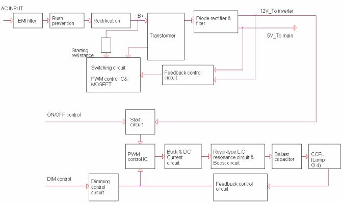
5.3Electrical Block Diagram
5.3.1Main Board
17
Dell E193FPc
5.3.2 Inverter/Power Board
18

Dell E193FPc
6. Mechanical Instruction
Tools: 2 Power screwdrivers (φ=5mm,L=60mm); 1 small cross screwdriver; turnbuckle driver; Setting: Power screwdriver torque A=11 kgF. Cm; torque B=6 kgF. Cm
Fig |
Remark |
1
Remove stand Remove the 4 screws and remove the stand ass’y by torque A
2
|
Remove the rear cover |
|
Pry the monitor up then find out the hooks’ |
|
position, use the tool (like the picture or |
3 |
other card) to insert into the gap of bezel |
and rear cover. |
Turn over the monitor as the Fig and take off the rear cover
19
Dell E193FPc
Cable hook
5 |
|
4 |
Remove bezel: |
|
|||
|
|
Disconnect the Key board connector and |
|
|
|
|
|
|
|
|
remove the bezel |
|
|
|
Note: When installing monitor fixes the |
|
|
|
cable use Black Adhesive Tape and screw |
|
6 |
the cable hook. |
|
Remove the small shield:
Remove the screws by Torque B
Symbol |
TPV Part Number |
Description |
|
|
|
|
|
4 |
095G8014 |
8 21 |
wire harness |
|
|
|
|
5 |
KEPC980KED1 |
Key Board |
|
|
|
|
|
6 |
015G8140 |
2 |
Main Frame |
|
|
|
|
20
Dell E193FPc
Remove the screw and push the small shield as the arrowhead direction by
Torque B or by manual
7
Remove the main frame:
Disconnect the back light connectors
Remove the four screws and remove the main frame by manual or torque = 3kgF.Cm
Symbol |
TPV Part Number |
Description |
|
|
|
7 |
085G 673 1 |
SHIELD-INVERTER |
|
|
|
21
Dell E193FPc
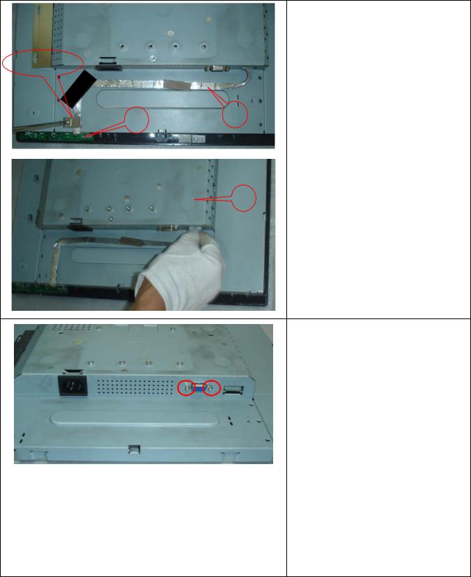
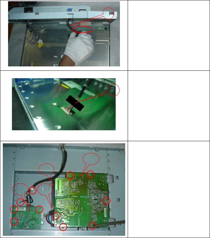
8
Remove the main frame and at the same time disconnect the LVDS connector
9
When installing monitor. Fix the LVDS by Black Adhesive Tape. 10mm should be kept between the tape and the connect end.
|
|
12 |
|
13 |
Remove the Power board and main |
|
|
|
|
|
board |
11 |
10 |
Remove the eight screws by Torque B |
|
|
And take off the Power board and main |
|
|
board. |
22

|
|
Dell E193FPc |
|
|
|
Installing the LVDS cable: |
|
|
|
Connect the LVDS cable with MB, and |
|
|
|
then fix the cable by screwing the cable |
|
B |
|
hook, and the ground end to the |
|
A |
|
mainframe. Make sure the ground line is |
|
C |
|
below signal lines. |
|
|
Ground |
Line C is power supply for the MB. |
|
Ground |
Connect the PB and MB directly; the |
||
|
|||
|
|
||
|
|
cable must not touch the pillar of screw. |
|
D |
|
|
|
|
|
|
|
|
|
The end |
|
|
|
The angle between CCFL line and vertical |
|
|
|
direction should be 30-40 degree. |
|
|
|
|
Symbol |
TPV Part Number |
Description |
Symbol |
TPV Part Number |
Description |
|
|
|
|
|
|
8 |
95G8018 30590/95G8018 30632 |
LVDS |
11 |
CBPC980KLLDR |
Main Board |
|
95G8018 30576 |
|
|
CBPC980KSLDR |
|
|
095G8018 30594 |
|
|
CBPC980KALDR |
|
|
|
|
|
|
|
9 |
052G 1150 C |
Black |
12 |
PWPC1942LGD1 |
Power |
|
|
Adhesive |
|
PWPC1942SED1 |
Board |
|
|
Tape |
|
PWPC1942AUD1 |
|
|
|
|
|
|
|
10 |
095G8014 6 19 |
Wire |
13 |
052G6025 11772 |
Mylar |
|
|
Harness |
|
|
|
|
|
|
|
|
|
23
Dell E193FPc
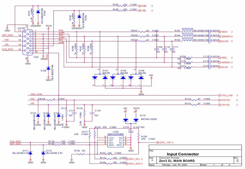
7. Schematic
7.1 Main Board
24
 Loading...