


17" LCD Color Monitor |
Dell E177FPc |
Service
Service
Service
|
|
Horizontal Frequency |
|
|
30 kHz to 81 kHz |
|
TABLE OF CONTENTS |
|
Description |
Page Description |
Page |
Table Of Contents.......…….................……...........…........1 Revision List.…........................………................……......2 ECN History.…........................………................……......3 Important Safety Notice.………….…..................……......4 1.Monitor Specifications..............................………........5 2.LCD Monitor Description…………………………….......6 3.Operation Instructions…………...............……...........7 3.1 General Instructions…………………………………….7 3.2.Control Buttons…………….…..............……...............7 3.3 On Screen Menu/Display (OSD).......….……..........8 3.4 Adjusting the Picture...........…………….........…..10 4.Input/Output Specification............………………......…10
4.1.Input Signal Connector............…………................10 4.2.Factory Preset Display Modes.........................11 4.3.Power Supply Requirements...............................12 4.4.Panel Specification.....………………..................12 4.5.Definition of Pixel.....………………...............……….12
5.Block Diagram…….…...................…………................14
5.1.Monitor Exploded View………………………............14
5.2.Software Flow Chart………..………………....….......24 5.3.Electrical Block Diagram………………..…..….......27 6.Schematic Diagram………..................................….....28
6.1Main Board......………......................................28
6.2 Power Board……..…….……....................................33
7.PCB Layout..……...………….......................................35 7.1.Main Board……………..…........................................35 7.2.Power Board……………........................................37 7.3.Key Board………………….....................................39 8.Maintainability………….......................................40 8.1.Equipments and Tools Requirement..…….…...........40 8.2.Trouble Shooting………………….............................41 9.White-Balance, Luminance adjustment...…………......49 10.ISP Instruction…………….…….................................51 11.Check List……………………………………………...55 12.BOM List………….....................................................58 13.Different Parts List…………..………………………… 93
SAFETY NOTICE
ANY PERSON ATTEMPTING TO SERVICE THIS CHASSIS MUST FAMILIARIZE HIMSELF WITH THE CHASSIS AND BE AWARE OF THE NECESSARY SAFETY PRECAUTIONS TO BE USED WHEN SERVICING ELECTRONIC EQUIPMENT CONTAINING HIGH VOLTAGES.
CAUTION: USE A SEPARATE ISOLATION TRANSFOMER FOR THIS UNIT WHEN SERVICING
1

17" LCD Color Monitor |
Dell E177FPc |
Revision List
Revision |
Release Date |
Revise history |
TPV model |
|
A00 |
May-26-2006 |
Initial Release |
T76CM5HKA2DFNP |
|
|
|
|
T76CM5HKA2DZNP |
|
|
|
|
T76CM9HKA2DFNCP |
|
A01 |
Jun-28-2006 |
Add new Model in Item 13 |
T76GM5HKA2DFNP |
|
|
|
|
T76GM5HKA2DZNP |
|
|
|
|
T76GM9HKA2DFNCP |
|
|
|
|
T76CM9HKA2DZNCP |
|
A02 |
Aug-21-2006 |
Add new Model in Item 13 |
T76CM9HMA2DZNCP |
|
|
|
|
T76GM9HMA2DFNCP |
|
A03 |
Aug-28-2006 |
Add new Model in Item 13 |
T76GM9HBA2DFNCP |
|
A04 |
Sep-11-2006 |
Add new Model in Item 13 |
T76AM9HKA2DFNP |
|
T76AM9HKA2DZNP |
||||
|
|
|
||
|
|
|
T76SM9HKA2DFNP |
|
A05 |
Sep-15-2006 |
Add new Model in Item 13 |
T76SM9HKA2DZNP |
|
|
|
|
T76CM9HJA2DRNCP |
|
A06 |
Sep-21-2006 |
Add new Model in Item 13 |
T76GM9HJA2DLNCP |
|
T76GM9HKA2DZNCP |
||||
|
|
|
||
|
|
|
T76CM9HMA2DFNCP |
|
|
|
|
T76CM9HMA2DLNCP |
|
A07 |
Oct-14-2006 |
Add new Model in Item 13 |
T76GM9HBA2DZNCP |
|
|
|
|
T76GM9HMA2DRNCP |
|
|
|
|
T76CM9HMA2DRNCP |
|
A08 |
Nov-14-2006 |
Add new Model in Item 12 |
T76CM9HJA2DLNCP |
|
|
|
|
T76CM9HBA2DFNCP |
|
|
|
|
T76GM9HJA2DRNCP |
|
|
|
|
T76GM9HMA2DZNCP |
|
|
|
|
T76SM9HBA2DFNCP |
|
A09 |
Nov-14-2006 |
Add new Model in Item 13 |
T76SM9HJA2DRNCP |
|
|
|
|
T76SM9HMA2DFNCP |
|
|
|
|
T76SM9HMA2DLNCP |
|
|
|
|
T76SM9HMA2DRNCP |
|
|
|
|
T76SM9HMA2DZNCP |
|
A10 |
Dec.-08-2006 |
Add new Model in Item 13 |
T76SM9HBA2DZNCP |
|
A11 |
May-14-2007 |
Add new Model in Item 12 |
T76AM9HMFDDDN |
|
|
|
|
T76AM9HMFDDGN |
|
|
|
|
T76KM9HKA2DFN |
|
A12 |
May-20-2007 |
Add new Model in Item 13 |
T76KM9HKA2DFNC |
|
|
|
|
T76SM9HMFDDDN |
|
|
|
|
T76SM9HMFDDGN |
|
A13 |
Jun-17-2007 |
Add new Model in Item 13 |
T76KM9HJA2DLNC |
|
T76KM9HMA2DFNC |
||||
|
|
|
||
A14 |
Dec.-05-2007 |
Add “ECN History” |
|
|
A15 |
Dec.-20--2007 |
Add the CBPC,PWPC Version |
All |
2

17" LCD Color Monitor |
Dell E177FPc |
ECN History
ECN No. |
Change Description |
Service Deposition |
Cut-in date |
MSR |
|
|
|
|
|
ECN-D-EE098 |
Firmware revision change from |
Update the Vista FW on VFF |
2006/12/29 |
A02 |
ECR02756 |
V1C02 to V1C03 |
return MFD before 2007-1-1 |
|
|
|
|
|
|
|
|
|
|
|
|
|
|
|
|
|
|
|
|
|
|
|
|
|
|
|
|
|
|
|
|
|
|
|
|
|
|
|
|
|
|
|
|
|
|
|
|
|
|
|
|
|
|
|
|
|
|
|
|
|
|
|
|
|
|
|
|
|
|
|
|
|
|
|
|
|
|
|
|
|
|
|
|
|
|
|
|
|
|
|
|
|
|
|
|
|
|
|
|
|
|
|
|
|
|
|
|
|
|
|
|
|
|
|
|
|
|
|
|
|
|
|
|
|
|
|
|
|
|
|
|
|
|
|
|
|
|
|
|
|
|
|
|
|
|
|
3

17" LCD Color Monitor |
Dell E177FPc |
Important Safety Notice
Proper service and repair is important to the safe, reliable operation of all AOC Company Equipment. The service procedures recommended by AOC and described in this service manual are effective methods of performing service operations. Some of these service operations require the use of tools specially designed for the purpose. The special tools should be used when and as recommended.
It is important to note that this manual contains various CAUTIONS and NOTICES which should be carefully read in order to minimize the risk of personal injury to service personnel. The possibility exists that improper service methods may damage the equipment. It is also important to understand that these CAUTIONS and NOTICES ARE NOT EXHAUSTIVE. AOC could not possibly know, evaluate and advise the service trade of all conceivable ways in which service might be done or of the possible hazardous consequences of each way. Consequently, AOC has not undertaken any such broad evaluation. Accordingly, a servicer who uses a service procedure or tool which is not recommended by AOC must first satisfy himself thoroughly that neither his safety nor the safe operation of the equipment will be jeopardized by the service method selected.
Hereafter throughout this manual, AOC Company will be referred to as AOC.
WARNING
Use of substitute replacement parts, which do not have the same, specified safety characteristics may create shock, fire, or other hazards.
Under no circumstances should the original design be modified or altered without written permission from Philips. AOC assumes no liability, express or implied, arising out of any unauthorized modification of design.
Servicer assumes all liability.
FOR PRODUCTS CONTAINING LASER:
DANGER-Invisible laser radiation when open. AVOID DIRECT EXPOSURE TO BEAM.
CAUTION-Use of controls or adjustments or performance of procedures other than those specified herein may result in hazardous radiation exposure.
CAUTION -The use of optical instruments with this product will increase eye hazard.
TO ENSURE THE CONTINUED RELIABILITY OF THIS PRODUCT, USE ONLY ORIGINAL MANUFACTURER'S REPLACEMENT PARTS, WHICH ARE LISTED WITH THEIR PART NUMBERS IN THE PARTS LIST SECTION OF THIS SERVICE MANUAL.
Take care during handling the LCD module with backlight unit
-Must mount the module using mounting holes arranged in four corners.
-Do not press on the panel, edge of the frame strongly or electric shock as this will result in damage to the screen. -Do not scratch or press on the panel with any sharp objects, such as pencil or pen as this may result in damage to the panel.
-Protect the module from the ESD as it may damage the electronic circuit (C-MOS). -Make certain that treatment person’s body is grounded through wristband.
-Do not leave the module in high temperature and in areas of high humidity for a long time. -Avoid contact with water as it may a short circuit within the module.
-If the surface of panel becomes dirty, please wipe it off with a soft material. (Cleaning with a dirty or rough cloth may damage the panel.)
4

17" LCD Color Monitor |
Dell E177FPc |
|||
1. Monitor Specifications |
|
|
||
|
|
|
|
|
|
|
Screen type |
Active matrix - TFT LCD |
|
|
|
|
|
|
|
LCD Panel |
Size |
430mm(17.0") |
|
|
|
|
|
|
|
Pixel pitch |
0.264mm(H) x 0.264mm(V) |
|
|
|
|
|
||
|
|
|
|
|
|
|
Response time |
8ms(type) |
|
|
|
|
|
|
|
|
Video |
R, G, B Analog Interface |
|
|
|
|
|
|
|
Input |
Separate Sync |
H/V TTL |
|
|
|
|
|
|
|
H-Frequency |
30kHz – 81kHz |
|
|
|
|
|
||
|
|
|
|
|
|
|
V-Frequency |
56 - 76Hz |
|
|
|
|
|
|
|
Display Colors |
16.2M Colors |
|
|
|
|
|
|
|
|
Dot Clock |
135MHz(Max) |
|
|
|
|
|
|
|
|
Max. Resolution |
1280 x 1024 |
|
|
|
|
|
|
|
|
Plug & Play |
VESA DDC |
|
|
|
|
|
|
|
|
|
ON Mode |
Maximum 40W; Typical 34W |
|
|
EPA ENERGY STAR® |
|
|
|
|
Power Saving |
<=2W |
|
|
|
|
OFF Mode |
<=1W |
|
|
|
|
|
|
|
Input Connector |
D-Sub 15pin |
|
|
|
Input Video Signal |
Analog:0. 7Vp-p(standard) |
|
|
|
75 OHM, Positive |
|
||
|
|
|
|
|
|
Active Display Area |
Horizontal : 337.92mm |
|
|
|
Vertical: 270.336mm |
|
||
|
|
|
|
|
|
|
|
|
|
|
Power Source |
100 V ~ 240 V± 10 %VAC, 50 ± 3Hz, 60 ± 3Hz |
|
|
|
|
|
|
|
|
Environmental |
Operating Temp: 5° to 35°C |
|
|
|
Operating Humidity: 10% to 80% |
|
||
|
Considerations |
|
||
|
Storage Temp.: -20° to 60°C |
|
||
|
|
|
|
|
|
|
|
|
|
|
|
|
Monitor (Stand and Head): 5.2kg |
|
|
|
|
|
|
|
Weight |
Monitor Flat panel only (VESA Mode): 4.0 kg |
|
|
|
|
|
|
|
|
|
|
Weight with packaging: 6.4 kg |
|
|
|
|
|
|
5

17" LCD Color Monitor |
Dell E177FPc |
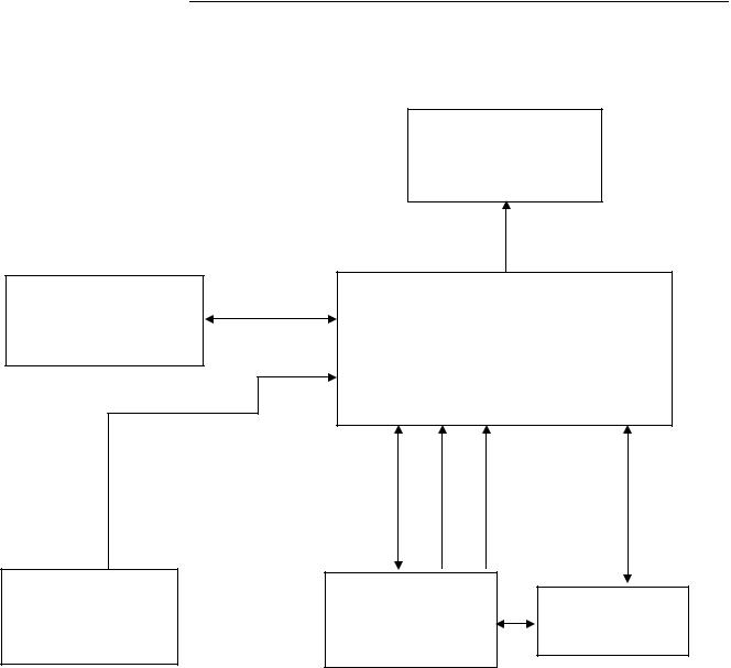
2. LCD Monitor Description
The LCD monitor will contain a main board, PWPC board, keypad board, which house the flat panel control logic, brightness control logic and DDC.
The power board will provide AC to DC Inverter voltage to drive the backlight of panel and the main board chips each voltage.
Monitor Block Diagram
|
CCFL Drive. |
|
|
Flat Panel and |
|
|
|
|||
|
|
|
|
|
|
CCFL backlight |
|
|
|
|
|
|
|
|
|
|
|
|
|
||
|
|
|
|
|
|
|
|
|
|
|
|
|
|
|
|
|
|
|
|
|
|
|
|
|
|
|
|
|
|
|
|
RS232 Connector |
|
|
|
|
|
|
|
|
|
|
|
Power board |
|
|
Main Board |
|
||||||
|
|
|
|
|
For white balance |
|||||
|
|
|
|
|
|
|
|
|
|
|
|
|
|
|
|
|
|
|
|
|
adjustment in factory |
|
|
|
|
|
|
|
|
|||
|
|
|
|
|
|
|
|
|||
|
|
|
|
|
|
|
|
|
|
mode |
|
|
|
|
Keyboard |
|
|
|
|||
|
|
|
|
|
|
|
|
|||
|
|
|
|
|
Video signal, DDC |
|||||
|
|
|
|
|
|
|||||
|
|
|
|
|
|
|||||
AC-IN |
|
|
|
|
|
|
|
|||
|
HOST Computer |
|
|
|
||||||
100-240V |
|
|
|
|
||||||
|
|
|
|
|
|
|
||||
|
|
|
|
|
|
|
||||
6

17" LCD Color Monitor |
Dell E177FPc |
3. Operation instructions
3.1 General Instructions
Press the power button to turn the monitor on or off. The other control buttons are located at front panel of the monitor. By changing these settings, the picture can be adjusted to your personal preferences.
-The power cord should be connected.
-Connect the video cable from the monitor to the video card.
-Press the power button to turn on the monitor, the power indicator will light up.
3.2Control Buttons
1 Menu selection button
2 Brightness Contrast / Down (-) button
3 Auto-Adjust / Up (+) button
4 Power button On/Off button with indicator
A
MENU
The 'MENU' button is used to open the on-screen display (OSD), select function icons, exit from menus and sub-menus, and to exit the OSD. See Accessing the Menu System.
B |
|
|
|
Use this button for direct access to the 'Brightness' and 'Contrast' control |
||
|
|
|
|
menu. |
|
|
|
|
Brightness/Contrast Hot Key |
|
|
|
|
|
|
|
|
|
|
|
|
|
|
|
|
||
B C |
|
|
|
Use these buttons to adjust (decrease/increase ranges) items in the OSD. |
||
|
|
- and + buttons |
|
|
|
|
|
|
|
|
|
|
|
|
|
|
||||
C |
|
|
|
Use this button to activate automatic setup and adjustment. The following |
||
|
|
|
|
dialog will appear on screen as the monitor self-adjusts to the current input: |
||
|
|
|
|
|
|
|
|
|
|
|
|
Auto Adjust In Progress |
|
|
|
Auto Adjust |
|
|
|
|
|
|
|
Auto Adjustment |
button allows the monitor to self-adjust to the |
||
|
|
|
|
|||
|
|
|
|
incoming video signal. After using 'Auto Adjustment', you can further tune |
||
|
|
|
|
your monitor by using the 'Pixel Clock' and 'Phase' controls in the OSD. |
||
|
|
|
|
|
||
|
|
|
||||
D |
|
|
|
The green LED indicates the monitor is on and fully functional. An amber |
||
|
|
|
|
LED indicates DPMS power save mode. |
||
|
|
Power Button & Indicator |
|
The Power button turns the monitor on and off. |
||
|
|
|
|
|
|
|
7
|
17" LCD Color Monitor |
|
|
Dell E177FPc |
||
|
3.3 On Screen Menu/Display (OSD) |
|
|
|
|
|
|
Direct-Access Functions |
|
|
|
|
|
|
|
|
|
|
|
|
|
Function |
|
Adjustment Method |
|
||
|
|
|
|
|
|
|
|
|
|
|
|||
|
Auto adjustment |
|
Use this button to activate automatic setup and |
|
||
|
|
|
adjustment. The following dialog will appear on |
|
||
|
|
|
screen as the monitor self-adjusts to the current |
|
||
|
|
|
input: |
|
||
|
|
|
|
|
|
|
|
|
|
|
Auto Adjust In Progress |
|
|
|
|
|
|
|
|
|
|
|
|
Auto Adjustment button allows the monitor to |
|
||
|
|
|
self-adjust to the incoming video signal. After using |
|
||
|
|
|
'Auto Adjustment', you can further tune your monitor |
|
||
|
|
|
by using the 'Pixel Clock' and 'Phase' controls in the |
|
||
|
|
|
OSD. |
|
||
|
|
|
NOTE: Auto Adjust will not occur if you press |
|
||
|
|
|
the button while there are no active video input |
|
||
|
|
|
signals, or attached cables |
|
||
|
|
|
|
|
|
|
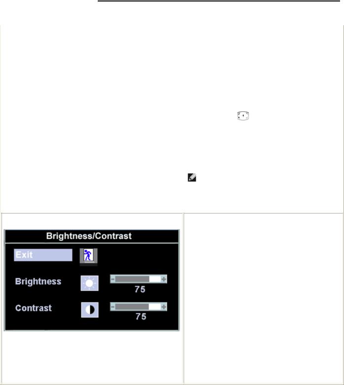
Brightness / Contrast
With the menu off, push  button to display the
'Brightness' and 'Contrast' adjustment menu.
The 'Brightness' function adjusts the luminance of the flat panel.
Adjust 'Brightness' first, then adjust 'Contrast' only if further adjustment is necessary.
"+" increase 'brightness' " - "decrease 'brightness'
The 'Contrast' function adjusts the degree of difference between darkness and lightness on the display screen.
"+" increase the 'contrast' "-" decrease the 'contrast'
8

17" LCD Color Monitor |
Dell E177FPc |
3.4 Adjusting the Picture
1.With the menu off, push the 'MENU' button to open the OSD system and display the main features menu.
A |
Function icons |
B |
Main Menu |
C |
Menu icon |
D |
Sub-Menu name |
E |
Resolution |
|
|
2.Push the - and + buttons to move between the function icons. As you move from one icon to another, the function name is highlighted to reflect the function or group of functions (sub-menus) represented by that icon. See the table below for a complete list of all the functions available for the monitor.
3.Push the 'MENU' button once to activate the highlighted function; Push -/+ to select the desired parameter, push menu to enter the slide bar. Then use the - and + buttons, according to the indicators on the menu, to make your changes.
4.Push the 'Menu' button once to return to the main menu to select another function or push the ‘Menu’ button two or three times to exit from the OSD.
9

17" LCD Color Monitor |
Dell E177FPc |
Icon |
|
Menu Name and |
|
Description |
|
|
Sub-menus |
|
|
|
|
|
|
|
|
|
|
|
|
|
|
EXIT |
|
This is used to exit out of the 'Main menu'. |
|
|
|
|
|
|
|
|
|
|
|
|
Positioning: |
|
'Positioning' moves the viewing area around on the monitor screen. |
|
|
Horizontal |
|
When making changes to either the 'Horizontal' or 'Vertical' settings, no changes will |
|
|
Vertical |
|
occur to the size of the viewing area; the image will simply be shifted in response to |
|
|
|
|
your selection/change. |
|
|
|
|
Minimum is '0' (-). Maximum is '100' (+). |
|
|
|
|
|
|
|
|
Image settings: |
|
|
|
|
|
|
Auto Adjust |
|
Even though your computer system can recognize your new flat panel monitor on |
|
|
|
|
|
|
startup, the 'Auto Adjustment' function will optimize the display settings for use with |
|
|
|
|
|
|
your particular setup. |
|
|
|
|
|
|
NOTE: In most cases, 'Auto Adjust' will produce the best image for your |
|
|
|
|
|
|
configuration; this function can be directly access via Auto Adjustment |
|
|
|
|
|
|
hotkey. |
|
|
|
|
Pixel Clock |
|
The 'Phase' and 'Pixel Clock' adjustments allow you to more closely adjust your monitor |
|
|
|
|
|
|
to your preference. These settings are accessed through the main OSD menu, by |
|
|
|
|
|
|
selecting 'Image Settings'. |
|
|
|
|
|
|
Use the - and + buttons to adjust away interference. Minimum: 0 ~ Maximum: 100 |
|
|
|
|
|
|
|
|
10
17" LCD Color Monitor |
Dell E177FPc |
Phase |
If satisfactory results are not obtained using the 'Phase' adjustment, use the 'Pixel |
|
Clock' adjustment and then use 'Phase' again. |
NOTE: This function may change the width of the display image. Use the 'Horizontal' function of the 'Position' menu to center the display image on the screen.
Color Settings: |
'Color Settings' adjusts the color temperature and saturation. |
Normal Preset |
'Normal Preset' is selected to obtain the default (factory) color settings. |
Blue Preset |
'Blue Preset' is selected to obtain a bluish tint. This color setting is typically used for text |
|
based applications (Spreadsheets, Programming, Text Editors etc.). |
Red Preset |
'Red Preset' is selected to obtain a redder tint. This color setting is typically used for |
|
color intensive applications (Photograph Image Editing, Multimedia, Movies etc.). |
11
17" LCD Color Monitor |
Dell E177FPc |
User Preset
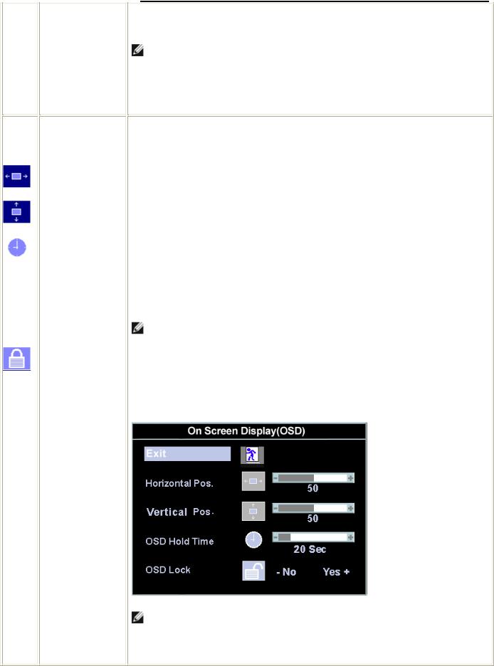
OSD Settings:
Horizontal Position
Vertical Position
OSD Hold Time:
OSD Lock
'User Preset': Use the plus and minus buttons to increase or decrease each of the three colors (R, G, B) independently, in single digit increments, from '0' to '100'.
NOTE: 'Color temperature' is a measure of the 'warmth' of the image colors (red/green/blue). The two available presets ('Blue' and 'Red') favor blue and red accordingly. Select each one to see how each range suits your eye; or utilize the 'User Preset' option to customize the color settings to your exact choice.
Each time the OSD opens, it displays in the same location on the screen. 'OSD Settings' (horizontal/vertical) provides control over this location.
-and + buttons move OSD to the left and right.
-and + buttons move OSD down and up.
The OSD stays active for as long as it is in use.
'OSD Hold Time': Sets the length of time the OSD will remain active after the last time you pressed a button.
Use the - and + buttons to adjust the slider in 5 second increments, from 5 to 60 seconds.
NOTE: Default 'OSD hold time' is 20 seconds.
'OSD Lock': Controls user access to adjustments. When 'Yes' (+) is selected, no user adjustments are allowed. All buttons are locked except the menu button.
All buttons can be locked or unlocked press the 'Menu' button for over 15 seconds. to unlock the OSD 'Menu'.
NOTE: When the OSD is locked, pressing the 'Menu' button will take the user directly to the 'OSD settings' menu, with 'OSD Lock' preselected on entry. Select 'No'(-) to unlock and allow user access to all applicable settings.
12

17" LCD Color Monitor |
Dell E177FPc |
Language:
Factory Reset:
Language sets the OSD to display in one of five languages (English, Español, Français, Deutsch, Japanese).
NOTE: The language chosen affects only the language of the OSD. It has no effect on any software running on the computer.
'Factory Reset' returns the settings to the factory preset values for the selected group of functions. 'Exit' is used to exit out of 'Factory Reset' menu.
For 'All settings', all user adjustable settings are reset at one time except 'Language settings'.
OSD Warning Messages
A warning message may appear on the screen indicating that the monitor is out of sync.
Cannot Display This Video Mode
Optimum resolution 1280 x1024 60Hz
This means that the monitor cannot synchronize with the signal that it is receiving from the computer. Either the signal is too high or too low for the monitor to use. See Specifications for the Horizontal and Vertical frequency ranges addressable by this monitor. Recommended mode is 1280 X 1024 @ 60Hz.
NOTE: The floating 'Dell - self-test Feature Check' dialog will appear on-screen if the monitor cannot sense a video signal.
Occasionally, no warning message appears, but the screen is blank. This could also indicate that the monitor is not synchronizing with the computer. See Troubleshooting for more information.
13

17" LCD Color Monitor |
|
Dell E177FPc |
|||
4. Input/Output Specification |
|
|
|
||
4.1 Input Signal Connector |
|
|
|
||
|
|
|
|
|
|
|
Pin No. |
Description |
Pin No. |
Description |
|
|
|
|
|
|
|
1. |
Red Video |
9. |
Computer 5V/3.3V |
||
|
|
|
|
|
|
2. |
Green Video |
10. |
GND-sync |
||
|
|
|
|
|
|
3. |
Blue Video |
11. |
GND |
||
|
|
|
|
|
|
4. |
GND |
12. |
DDC-Serial Data |
||
|
|
|
|
|
|
5. |
Self-test |
13. |
H-Sync |
||
|
|
|
|
|
|
6. |
R-Ground |
14. |
V-Sync |
||
|
|
|
|
|
|
7. |
G-Ground |
15. |
DDC-Serial Clock |
||
8.B-Ground
VGA Connector layout
1 |
5 |
6 |
10 |
11 |
15 |
4.2 Factory Preset Display Modes
VESA MODES |
|
|
|
|
|
|
|
|
|
|
|
|
|
|
|
|
|
|
|
|
Horizontal |
|
|
Vertical |
|
|
|
|
|
|
|
|
|
|
|
|
|
|
Nominal |
|
Sync |
Nominal |
Sync |
Nominal |
Mode |
Resolution |
Total |
Frequency |
|
Polarit |
|||
|
Freq.+/- 1Hz |
Polarity |
Pixel Clock (MHz) |
|||||
|
|
|
+/- 0.5kHz |
|
y |
|||
|
|
|
|
|
|
|
||
|
|
|
|
|
|
|
|
|
|
640x480@60Hz |
800 x 525 |
31.469 |
|
N |
59.940 |
N |
25.175 |
|
|
|
|
|
|
|
|
|
VGA |
640x480@75Hz |
840 x 500 |
37.500 |
|
N |
75.00 |
N |
31.500 |
|
|
|
|
|
|
|
|
|
800x600@60Hz |
1056 x 628 |
37.879 |
|
P |
60.317 |
P |
40.000 |
|
|
|
|||||||
|
|
|
|
|
|
|
|
|
|
800x600@75Hz |
1056x625 |
46.875 |
|
P |
75.000 |
P |
49.500 |
|
|
|
|
|
|
|
|
|
XGA |
1024x768@60Hz |
1344x806 |
48.363 |
|
N |
60.004 |
N |
65.000 |
|
|
|
|
|
|
|
|
|
1024x768@75Hz |
1312x800 |
60.023 |
|
P |
75.029 |
P |
78.750 |
|
|
|
|||||||
|
|
|
|
|
|
|
|
|
|
1152x864@75Hz |
1600x900 |
67.500 |
|
P |
75.000 |
P |
108.00 |
|
|
|
|
|
|
|
|
|
SXGA |
1280x1024@60Hz |
1688x1066 |
64.000 |
|
P |
60.000 |
P |
108.00 |
|
|
|
|
|
|
|
|
|
|
1280x1024@75Hz |
1688x1066 |
79.976 |
|
P |
75.025 |
P |
135.00 |
|
|
|
|
|
|
|
|
|
IBM MODES |
|
|
|
|
|
|
|
|
|
|
|
|
|
|
|
|
|
|
|
|
Nominal |
|
Sync |
Nominal |
Sync |
Nominal Pixel |
Mode |
Resolution |
Total |
Frequency |
|
Polarit |
Freq. +/- 1 |
||
|
Polarity |
Clock (MHz) |
||||||
|
|
|
+/- 0.5kHz |
|
y |
Hz |
||
|
|
|
|
|
|
|||
|
|
|
|
|
|
|
|
|
DOS |
720x400@70Hz |
900 x 449 |
31.469 |
|
N |
70.087 |
P |
28.322 |
|
|
|
|
|
|
|
|
|
14

17" LCD Color Monitor |
Dell E177FPc |
|||
4.3 Power Supply Requirements |
|
|
||
|
|
|
|
|
|
A/C Line voltage range |
|
100 V ~ 240 V± 10 % |
|
|
|
|
|
|
|
A/C Line frequency range |
|
50 ± 3Hz, 60 ± 3Hz |
|
|
|
|
|
|
|
Input Voltage transients |
|
280 volts AC for 10 sec @40 |
|
|
|
|
|
|
|
Current |
|
0.6A max. at 100V, 0.35A max. at 240 V |
|
|
|
|
|
|
|
Peak surge current |
|
< 60A peak at 240 VAC and cold starting |
|
|
|
< 30A peak at 120VAC and cold starting |
|
|
|
|
|
|
|
|
Leakage current |
|
< 3.5mA |
|
|
Power line surge |
|
No advance effects (no loss of information or defect) |
|
|
|
with a maximum of 1 half-wave missing per second |
|
|
|
|
|
|
|
|
|
|
|
|
15

17" LCD Color Monitor |
Dell E177FPc |
4.4 Panel Specification
4.4.1 Display Characteristics For LM170E01-TLB3 panel
For LM170E01-TLB4 panel
For CLAA170EA07Q Rev.373/3A3 panel
16

17" LCD Color Monitor |
Dell E177FPc |
Optical Characteristics
For LM170E01TLB3/TLB4 panel
17

17" LCD Color Monitor |
Dell E177FPc |
For CLAA170EA07Q Rev.373/3A3 panel
18

17" LCD Color Monitor |
Dell E177FPc |
4.5 Definition Of Pixel Defects
For LM170E01TLB3/TLB4 panel Dot Defect
Bright Dot
Dots (sub-pixels), which appeared brightly in the screen when the LCM displayed with dark pattern.
- R, G or B 1 dot --------------------------------- |
0 Max |
- Adjacent 2 dots -------------------------------- |
0 Max |
- Total amount of Bright dots -------------------- |
0 Max |
- Minimum distance of Bright dots --------------- |
NA |
Dark Dot |
|
Dots (sub-pixels) which appeared darkly in the screen when the LCM displayed with bright pattern.
- 1 dot -------------------------------------------- |
4 Max |
- Adjacent 2 dots -------------------------------- |
2 Max |
- Total amount of Dark dot ---------------------- |
4 Max |
- Minimum distance of Dark dots --------------- |
15mm |
Total amount of Dot Defects -------------------- |
5 Max (Combination) |
Note) a. Every dot herein means Sub-Pixel (Each Red, Green, or Blue Color) b. Bright dot
-Red or Blue dots smaller than half size of sub-pixel are not counted as a defect dots.
-Green dots smaller than 1 / 3 size of sub-pixel are not counted as a defect dots.
c. Dark dots smaller than half size of sub-pixel are not counted as a defect dots.
Polarizer Defects
Where, W: Width
L: Length
D:Average diameter =(a+b)/2
a.Extraneous substances, which can be wiped out, like Finger Print, Particles, are not considered as a defect.
b.Defects which are on the Black Matrix (outside of Active Area) are not considered as a defect.
19

17" LCD Color Monitor |
Dell E177FPc |
Foreign Material
Where, W: Width
L: Length
D: Average diameter =(a+b)/2
Line Defect
All kinds of line defects such as vertical, horizontal or cross are not allowed.
Bezel Appearance
Scratches, minor bents, stain, particles on the Bezel frame are not considered as a defect.
others
Issues, which are not defined in these criteria, shall be discussed with both parties, Customer and Supplier, for better solution.
20
17" LCD Color Monitor |
Dell E177FPc |
For CLAA170EA07Q Rev.373/3A3 panel
21

17" LCD Color Monitor |
Dell E177FPc |
22
17" LCD Color Monitor |
Dell E177FPc |
5.Block Diagram
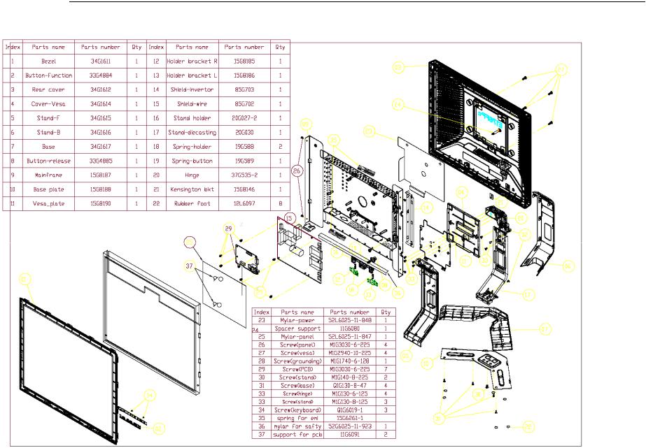
5.1Monitor Exploded View
23
17" LCD Color Monitor |
Dell E177FPc |
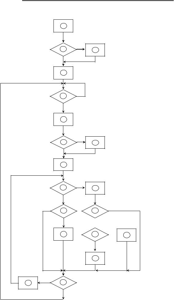
5.2 Software Flow Chart
1
2
4
5 Y
6
7
9
|
10 |
|
Y |
N |
12 |
|
|
|
Y |
|
14 |
Y
3
N
N
N
8
Y
N
11
N
13
 Y
Y
N
15  16
16
Y
17
18 N 19
Y
24

17" LCD Color Monitor |
Dell E177FPc |
1)MCU Initializes.
2)Is the EEprom blank?
3)Program the EEprom by default values.
4)Get the PWM value of brightness from EEprom.
5)Is the power key pressed?
6)Clear all global flags.
7)Are the AUTO and SELECT keys pressed?
8)Enter factory mode.
9) Save the power key status into EEprom. Turn on the LED and set it to green color. Scalar initializes.
10)In standby mode?
11)Update the lifetime of back light.
12)Check the analog port, are there any signals coming?
13)Does the scalar send out an interrupt request?
14)Wake up the scalar.
15)Are there any signals coming from analog port?
16)Display "No connection Check Signal Cable" message. And go into standby mode after the message disappears.
17)Program the scalar to be able to show the coming mode.
18)Process the OSD display.
19)Read the keyboard. Is the power key pressed?
25
17" LCD Color Monitor
5.3 Electrical Block Diagram
5.3.1 Main Board
Flash Memory
SST25VF010A-33- 4C-SAE
(U402)
OSD Control Interface
(CN403)
Dell E177FPc
LCD Interface
(CN101)
Scalar TSUM16AL-LF
(Include MCU, ADC, OSD)
(U401)
|
R |
H |
|
RXD |
|
||
G |
DB15_SDA, |
||
TXD |
|
V |
|
B |
DB15_SCL |
||
|
D-Sub
EEPROM M24C02
Connector
(U404)
(CN405)
26

17" LCD Color Monitor |
Dell E177FPc |
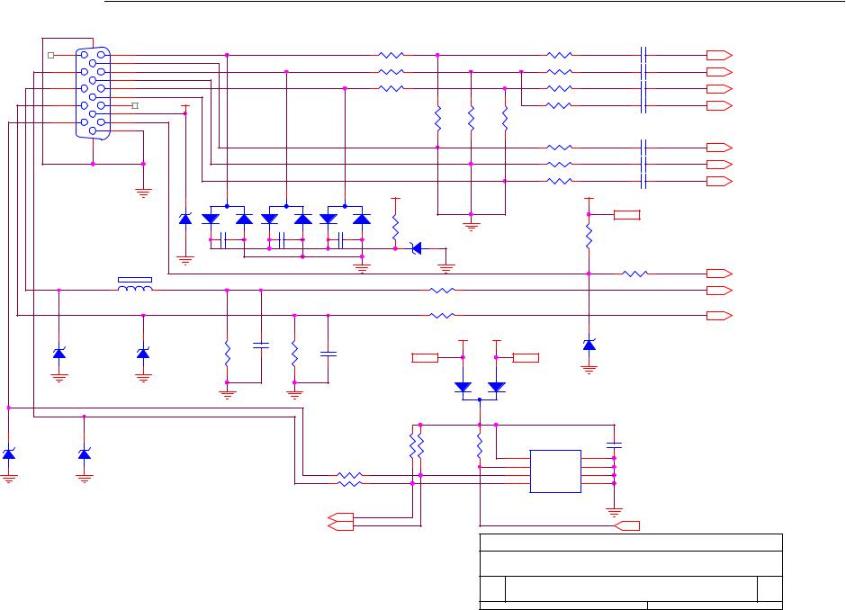
5.3.2 Inverter/Power Board
27

17" LCD Color Monitor |
Dell E177FPc |
6. Schematic Diagram
6.1 Main Board
TSUM16AL SCHEMATIC
|
|
XGA/SXGA |
|
|
LVDS OUTPUT |
|||||||||||||
|
|
|
B3 |
|
|
B4 |
|
|
|
|
|
|
|
|
|
|
|
|
|
|
|
|
|
RIN |
|
RIN |
|
VCC1.8 VCC3.3 +5V |
|||||||||
|
|
|
|
|
|
|
|
|
|
|
|
|
|
|
|
|
||
+5V |
GNDR |
|
GNDR |
|
|
|
|
|
|
|
|
|
|
|
||||
GIN |
|
GIN |
|
|
|
|
|
|
|
|
|
|
|
|||||
|
|
|
|
|
|
|
|
|
|
|
|
|
|
|
|
|
||
|
|
|
|
|
GNDG |
|
GNDG |
VCC1.8 |
|
|
|
|
|
|
|
|
||
|
|
|
|
|
SOG |
|
SOG |
|
|
|
|
|
|
|
|
|
|
|
|
|
|
|
|
|
|
|
|
|
|
|
|
|
|
|
|
||
|
|
|
|
+5V |
BIN |
|
BIN |
Vcc3.3 |
|
|
|
|
|
|
|
|||
|
|
|
|
|
|
|
|
|
||||||||||
PC5V |
GNDB |
|
GNDB |
|
|
|
|
|
|
|
|
|
|
|
||||
|
|
|
|
|
|
|
|
|
|
|
|
|||||||
HSYNC |
|
HSYNC |
+5V |
|
|
|
|
|
|
|
|
|
|
|||||
|
|
|
|
|
|
|
|
|
|
|
|
|
||||||
|
|
|
|
|
VSYNC |
|
VSYNC |
|
|
|
|
|
|
|
|
|
|
|
|
|
|
|
|
DDCA_SDA |
|
DDCA_SDA |
|
|
|
|
|
|
|
|
|
|
|
|
|
|
|
|
|
|
|
|
|
|
|
|
|
|
|
|
||
|
|
|
|
PC5V |
DDCA_SCL |
|
DDCA_SCL |
|
|
|
|
|
|
|
|
|
|
|
VCC3.3 |
DET_VGA |
|
DET_VGA |
|
|
|
|
|
|
|
|
|
|
|
||||
|
|
|
|
|
|
|
|
|
|
|
|
|||||||
|
|
|
|
|
|
|
|
|
|
|
|
|
|
|||||
|
|
|
|
|
|
|
|
|
|
|
|
|
|
|
|
|
|
|
|
|
|
VCC3.3 |
DDC_WP |
DDC_WP |
|
|
|
|
|
|
|
|
|
|
|
|
|
3.INPUT |
|
|
|
|
|
|
|
|
|
|
B5 |
|
|
|
|
|
|
A[0..9] |
A[0..9] |
|
|
|
|
|
|
A[0..9] |
|
|
VCC3.3 |
+5V |
VCC1.8 |
PC5V |
|
B[0..9] |
B[0..9] |
|
|
|
|
B2 |
|
B[0..9] |
VLCD |
|
|
|
|
|
|
|
||
|
|
|
|
on_BACKLIGHT |
on_BACKLIGHT |
|
|
|
|
|
|
on_Panel |
on_Panel |
VLCD |
|
|
|
|
|
|
|
|
|
|
|
|
PC5V |
VCTRL |
VCTRL |
|
|
|
|
|
VCC1.8 |
|
|
|
|
|
|
|
+5V |
Adj_BACKLIGHT |
Adj_BACKLIGHT |
|
|
|
|
|
VCC3.3 |
VLCD |
|
|
|
|
|
|
|
|
|
|
|
|
|
|
|
VLCD |
|
|
|
|
|
|
2.POWER |
4.SCALER |
5.PANEL INTERFACE |
|
|
Title |
AOC TSUM16AL |
|
|
|
|
||
Size |
Document Number |
|
Rev |
A |
TOP |
|
A |
|
|
||
Date: |
Tuesday, May 16, 2006 |
Sheet |
1 of 5 |
28

17" LCD Color Monitor |
Dell E177FPc |
|
|
|
|
|
|
|
|
|
|
|
|
|
+5V |
|
|
|
|
|
|
|
|
|
|
|
|
|
|
|
|
|
|
|
|
|
|
|
|
|
|
|
R701 |
|
|
|
|
|
|
|
|
|
|
|
VCTRL |
4 |
|
|
|
|
|
|
|
|
|
|
|
|
|
|
|
|
|
|
|
|
|
|
|
|
|
|
|
|
|
|
|
|
|
|
|
|
|
|
|
|
|
|
1K 1/16W |
|
|
|
|
|
|
|
|
|
R702 |
|
|
|
|
|
|
|
|
|
|
|
|
|
|
|
|
|
|
|
|
|
|
|
|
|
|
|
|
|
|
|
|
|
|
|
|
|
|
CN701 |
|
|
|
|
|
|
|
|
|
|
|
|
|
|
|
|
51 1/16W |
|
|
|
|
|
|
|
|
GND |
1 |
|
2 |
BL_ON |
|
|
|
R705 |
|
R706 |
NC |
|
|
|
|
|
|
|
|
|
|
|
|
|
|
|
|
GND |
3 |
|
4 |
BL_ADJ |
|
|
|
4.7K 1/16W |
|
|
|
|
|
|
|
|
|
|
|
|
VCC1.8 |
|
|
|
|
|
|
GND |
5 |
|
6 |
|
+5V |
|
C708 |
|
|
|
|
|
|
|
|
|
|
|
C702 |
+ |
|
|
|
|
|
|
+5V |
7 |
|
8 |
GND |
|
|
|
|
|
R707 |
|
Adj_BACKLIGHT |
4 |
|
|
|
|
4.7uF/16V |
VCC1.8 |
4 |
||||
3,4 |
+5V |
|
|
+5V |
9 |
|
10 |
+5V |
|
0.1uF/16V |
|
Q701 |
|
|
|
|
|
|
|
|
|||||||
|
|
GND |
11 |
|
12 |
GND |
|
|
|
PMBS3904 |
4.7K 1/16W |
|
|
|
|
|
|
|
D701 |
|
|
|
|||||
|
|
|
|
|
|
R708 |
|
|
|
|
|
|
|
|
|
|
|
||||||||||
|
|
|
|
|
|
|
|
|
|
|
|
|
|
+5V |
|
|
|
|
|
|
|
|
|
|
|
|
|
|
|
|
|
|
|
|
|
|
10K 1/16W |
|
|
|
|
|
|
|
|
|
C |
LL4148 |
|
|
|
||||
|
|
|
|
|
|
|
|
|
|
|
|
|
|
|
|
|
|
|
|
|
|
|
|
|
|||
|
C709 |
|
|
|
|
CONN |
|
|
|
|
R710 |
NC |
|
|
|
|
|
|
|
|
B |
|
R703 |
|
|
||
|
|
+ |
C710 |
|
|
|
|
|
|
|
|
|
|
|
|
|
|
Q702 |
|
|
|
||||||
|
|
|
|
|
|
|
|
|
|
|
|
|
|
|
|
|
|
|
|
|
|
|
|
|
|||
|
0.1uF/16V |
|
|
100uF/16V |
|
|
|
C711 |
|
|
|
|
|
R711 |
|
|
|
|
D702 |
E |
CHT2907 |
|
2K 1/16W |
|
|
||
|
|
|
|
|
|
|
|
|
NC |
|
|
|
|
|
10K 1/16W |
|
|
|
|
|
|
|
|
|
|||
|
|
|
|
|
|
|
|
|
|
|
|
|
|
|
|
|
|
LL4148 |
|
|
|
|
|
|
|||
|
|
|
|
|
|
|
|
|
Q703 |
|
R712 |
|
|
|
|
|
|
C705 |
|
|
|
|
|
|
|
||
|
|
|
|
|
|
|
|
|
|
|
|
|
on_BACKLIGHT 4 |
|
|
|
|
|
|
|
|
|
|
||||
|
|
|
|
|
|
|
|
|
PMBS3904 |
4.7K 1/16W |
|
|
|
|
|
|
|
|
|
|
|
|
|
|
|||
|
|
|
|
|
|
|
|
|
|
|
|
|
|
|
+ |
|
|
|
|
|
|
|
|
|
|||
|
|
|
|
|
|
|
|
|
|
|
|
|
|
|
|
|
|
|
R704 |
|
|
|
|
|
|
||
|
|
|
|
|
|
|
|
|
|
|
|
|
|
|
|
|
1uF/16V |
|
|
|
|
|
|
|
|||
|
BL_ADJ(DC) |
R705 |
C708 |
R706 |
R701 |
R707 |
Q701 |
|
|
|
|
|
|
|
|
|
|
|
100 1/16W |
|
VCC3.3 |
|
|
|
|||
|
|
|
|
|
|
|
|
|
|
|
|
|
|
|
|
|
|
|
|
||||||||
|
0V ~ 3.3V |
4.7K |
1UF |
0 |
X |
X |
X |
|
|
|
|
|
|
|
|
|
|
|
|
|
|
|
|
|
|
|
|
|
0V ~ 5V |
|
4.7K |
1UF |
X |
1K |
4.7K |
MMBT3904 |
|
|
|
|
|
|
|
|
|
|
|
|
|
|
|
|
VCC3.3 |
3,4 |
|
|
BL_ADJ |
R705 |
C708 |
|
|
|
|
|
|
|
|
|
|
|
|
|
|
|
|
|
|
|
|
|
|
|
|
|
P W M |
47 |
N.C |
|
|
|
|
|
|
|
|
|
|
|
|
|
|
|
|
|
|
|
|
|
|
|
|
|
D C |
4K7 |
1uF |
|
|
|
|
|
|
|
|
|
|
|
+5V |
+5V |
PC5V |
|
|
|
|
|
|
|
|
|
|
|
|
|
|
|
|
|
|
|
|
|
|
|
|
|
|
|
|
|
PC5V |
|
3 |
|
|
|
|
|
|
|
|
|
|
+5V |
|
|
+5V |
VLCD |
|
+5V |
VCC3.3 |
|
|
|
|
R709 |
D703(BAT54) Vf=0.53V (worst cauae) when |
||||||||||
|
|
|
|
|
|
|
|
|
|
VLCD |
5 |
|
|
|
|
|
|
NC |
If=100mA. So when system power off, the |
||||||||
|
|
|
|
|
|
|
|
R714 |
|
|
|
|
3,4 |
|
+5V |
2 |
1 |
|
system loading is about 32mA, it is |
|
|||||||
|
|
|
|
R717 |
|
|
10K 1/16W |
|
|
|
R721 |
R722 |
|
D704 |
|
|
|
safe. |
TO-263 |
|
|
|
|
||||
|
|
|
|
10K 1/16W |
|
|
|
|
|
|
|
D703 |
|
|
|
|
|
|
|||||||||
|
|
|
|
|
|
|
|
|
0 1/16W |
NC |
|
SSM12L |
|
|
|
|
|
|
|
|
|||||||
|
|
|
|
|
|
|
|
R723 |
Q704 |
|
|
|
|
|
NC/BAT54C-GS08 |
|
|
|
|
||||||||
|
|
|
|
|
|
|
|
51K 1/16W |
AO3401L |
|
|
|
|
|
|
|
|
|
|
|
|
|
|
|
|||
|
|
|
|
|
|
|
|
|
|
|
|
|
|
|
|
|
|
U701 |
AIC1084-33PM |
|
VCC3.3 |
|
|
|
|||
|
R725 4.7K 1/16W |
Q706 |
|
3 |
|
|
|
2 |
|
4 |
on_Panel |
|
3 |
VIN |
|
VOUT |
VCC3.3 3,4 |
||
PMBS3904 |
|
|
ADJ |
4 |
|||||
|
|
|
|
|
VOUT |
|
|||
|
|
C715 |
|
|
|
|
|
||
|
|
|
|
|
|
|
|
||
|
|
|
|
|
|
|
|
|
|
|
C718 |
0.1uF/16V |
|
C713 |
|
|
|
+ |
C714 |
|
0.1uF/16V |
+ C717 |
R727 |
0.1uF/16V |
|
1 |
|
C712 |
0.1uF/16V |
|
|
10uF/16V |
10K 1/16W |
|
|
|
100uF/16V |
||
|
|
|
|
|
|
|
|
|
|
H2 |
|
|
|
H3 |
|
|
|
8 7 6 |
|
|
|
8 7 6 |
|
|
9 |
8 7 6 |
5 |
9 |
8 7 6 |
5 |
||
|
9 |
5 |
4 |
|
9 |
5 |
4 |
|
1234 |
|
1234 |
||||
|
|
|
|
||||
|
|
|
TP |
|
|
|
TP |
|
1 2 3 |
|
|
|
1 2 3 |
|
|
FTD7 |
FTD8 |
FTD9 |
|
|
|
||
FD Mark |
FD Mark |
FD Mark |
|
|
|||
9
H1
8 |
7 |
6 |
|
|
5 |
|
|
|
|
|
|
||
8 7 6 |
|
|||||
9 |
|
|
5 |
|
|
|
1234 |
|
4 |
||||
|
|
|
||||
|
TP |
|||||
|
|
|
|
|
||
|
|
|
|
|
||
1 2 3 |
|
|
|
|
||
Title |
|
AOC TSUM16AL |
|
|
|
|
|
||
Size |
Document Number |
|
Rev |
|
Custom |
POWER |
|
A |
|
|
|
|
||
Date: |
|
Tuesday, May 16, 2006 |
Sheet 2 |
of 5 |
29
17" LCD Color Monitor |
Dell E177FPc |
17 |
CN405 |
|
|
|
|
|
|
|
|
|
|
|
|
|
|
|
|
|
|
|
|
|
|
|
|
|
|
11 |
1 |
RED+ |
|
|
|
|
|
|
|
|
|
FB410 |
|
|
|
|
R434 |
|
56 1/16W |
C432 |
0.047uF |
|
|
RIN |
4 |
||
|
6 |
RED- |
|
|
|
|
|
|
|
|
|
0 1/16W |
|
|
|
|
|
|
|
|
|
|
|
||||
|
|
|
|
|
|
|
|
|
|
|
|
|
|
|
|
|
|
|
|
|
|
|
|||||
12 |
2 |
GREEN+ |
|
|
|
|
|
|
|
|
|
FB411 |
|
|
|
|
R435 |
|
56 1/16W |
C433 |
0.047uF |
|
|
GIN |
4 |
||
|
7 |
GREEN- |
|
|
|
|
|
|
|
|
|
0 1/16W |
|
|
|
|
|
|
|
|
|
|
|
||||
|
|
|
|
|
|
|
|
|
|
|
|
|
|
|
|
|
|
|
|
|
|
|
|||||
13 |
3 |
BLUE+ |
|
|
|
|
|
|
|
|
|
FB412 |
|
|
|
|
R436 |
|
56 1/16W |
C434 |
0.047uF |
|
|
BIN |
4 |
||
|
8 |
BLUE- |
|
|
|
|
|
|
|
|
|
0 1/16W |
|
|
|
|
|
|
|
|
|
|
|
||||
|
|
|
|
|
|
|
|
|
|
R439 1/16W75 |
|
1/16W75 |
|
|
|
|
|
|
|
|
|
|
|||||
14 |
4 |
PC5V |
|
|
|
|
|
|
|
|
|
|
|
|
R440 |
R437 |
|
NC |
C435 |
0.001uF NC |
|
SOG |
4 |
||||
|
9 |
PC5V |
|
|
|
|
|
|
|
|
|
|
R438 |
|
|
|
|
|
|
|
|
||||||
|
|
|
|
|
|
|
|
|
|
|
|
|
|
|
|
|
|
|
|
|
|
||||||
|
|
|
|
|
|
|
|
|
|
|
|
|
|
|
|
|
|
|
|
|
|
|
|
||||
15 |
5 |
VGA_CON |
|
|
|
|
|
|
|
|
|
75 1/16W |
|
|
|
|
|
|
|
|
|
|
|
|
|
||
|
10 |
|
|
|
|
|
|
|
|
|
|
|
|
|
|
|
|
|
|
|
|
|
|
|
|||
16 |
DB15 |
|
|
|
|
|
|
|
|
|
|
|
|
|
|
|
|
R441 |
|
100 1/16W |
C436 |
0.047uF |
|
|
GNDR |
4 |
|
|
|
|
|
|
|
|
|
|
|
|
|
|
|
|
|
|
|
|
|
|
|
|
|
|
|||
|
|
|
|
|
|
|
|
|
|
|
|
|
|
|
|
|
R442 |
|
100 1/16W |
C437 |
0.047uF |
|
|
|
|
||
|
|
|
|
|
|
|
|
|
|
|
|
|
|
|
|
|
|
|
|
|
GNDG |
4 |
|||||
|
|
|
|
|
|
|
|
|
|
|
|
|
|
|
|
|
|
|
|
|
|
|
|
|
|
||
|
|
|
|
|
|
|
|
|
|
|
|
|
|
|
|
|
|
R443 |
|
100 1/16W |
C438 |
0.047uF |
|
|
GNDB |
4 |
|
|
|
|
3 |
|
|
3 |
|
|
3 |
|
|
|
|
|
|
|
|
|
|
|
|
|
|
|
|||
|
|
|
D403 |
|
D404 |
|
D405 |
+5V |
|
|
|
|
|
|
|
|
+5V |
|
|
|
|
|
|
||||
|
|
|
|
|
|
|
|
|
|
|
|
|
|
|
|
|
|
|
|
|
|
|
|||||
|
|
D406 |
|
BAV99 |
|
|
|
BAV99 |
|
|
BAV99 |
|
|
|
|
|
|
|
|
|
|
|
|
|
|
|
|
|
|
|
|
|
|
|
|
|
|
|
|
R455 |
|
|
|
|
|
|
|
|
|
+5V |
2,4 |
|
|
|
|
|
|
|
|
|
|
|
|
|
|
|
|
|
|
|
|
|
|
|
|
|
|
|
|
|
|||
|
LL5232B 5.6V 5% |
|
|
|
|
|
|
|
|
|
|
|
|
|
|
|
|
|
R444 |
|
|
|
|
|
|
||
|
|
|
|
|
|
|
|
|
|
1K 1/16W |
|
|
|
|
|
|
|
|
|
|
|
|
|||||
|
|
C439 |
0.1uF/16VC440 |
0.1uF/16VC441 |
0.1uF/16V |
|
|
D413 |
|
|
|
|
|
|
10K 1/16W |
|
|
|
|
||||||||
|
|
2 |
|
1 |
2 |
|
|
1 |
2 |
|
1 |
|
|
LL5232B 5.6V 5% |
|
|
|
|
|
|
|
|
|||||
|
|
|
|
|
|
|
|
|
|
|
|
|
|
|
|
|
|
|
|
|
R445 |
100 1/16W |
|
DET_VGA 4 |
|||
|
|
|
|
|
|
|
|
|
|
|
|
|
|
|
|
|
|
|
|
|
|
|
|
|
|
||
HSI FB409 |
120 OHM BEAD |
|
|
|
|
|
|
|
|
|
|
R446 |
1K 1/16W |
|
|
|
|
|
|
|
|
|
HSYNC |
4 |
|||
|
|
|
|
|
|
|
|
|
|
|
|
|
|
|
|
|
|
|
|
|
|
|
|
|
|
||
VSI |
|
|
|
|
|
|
|
|
|
|
|
|
R447 |
1K 1/16W |
|
|
|
|
|
|
|
|
|
VSYNC |
4 |
||
|
|
|
1/16W |
|
|
22pF1/16W |
|
|
|
|
|
|
|
|
|
|
|
|
|
|
|
|
|
|
|||
LL5232B 5.6V 5% |
LL5232B 5.6V 5% |
|
|
|
|
|
2,4 |
VCC3.3 |
|
VCC3.3 |
PC5V |
PC5V |
|
2 |
|
|
|
|
|
|
|||||||
D408 |
|
D409 |
|
R448 |
|
C442 |
R449 |
C443 |
|
|
|
|
|
|
D410 |
|
|
|
|
|
|
||||||
|
2.2K |
|
|
2.2K |
|
|
|
|
|
|
|
|
|
LL5232B 5.6V 5% |
|
|
|
|
|||||||||
|
|
|
|
|
|
|
|
22pF |
|
|
|
2 |
1 |
|
|
|
|
|
|
|
|
|
|
|
|||
|
|
|
|
|
|
|
|
|
|
|
|
|
|
|
|
|
|
|
|
|
|
|
|
|
|
||
|
|
|
|
|
|
|
|
|
|
|
|
|
|
|
|
|
D407 |
|
|
|
|
|
|
|
|
|
|
|
|
SCL_VGA |
|
|
|
|
|
|
|
|
|
|
|
|
|
BAT54C |
|
|
|
|
|
|
|
|
|
||
|
|
SDA_VGA |
|
|
|
|
|
|
|
|
|
|
|
|
|
|
|
|
|
|
|
|
|
|
|
|
|
|
|
|
|
|
|
|
|
|
|
|
|
|
1/16W |
|
3 |
|
|
|
|
|
|
|
|
|
|
|
|
LL5232B 5.6V 5% |
LL5232B 5.6V 5% |
|
|
|
|
|
|
|
|
10K 1/16W |
|
1/16W |
|
8 |
|
|
|
1 |
0.1uF/16V |
|
|
|
|
||||
D411 |
D412 |
|
|
|
|
|
|
|
|
|
|
R450 |
|
R451R452 |
|
|
U404 |
|
|
|
C444 |
|
|
|
|
|
|
|
|
|
|
|
|
|
|
|
|
|
|
|
|
|
|
|
|
|
|
|
|
|
|
|
|||
|
|
|
|
|
|
|
|
|
|
|
|
|
|
|
|
|
|
|
|
|
|
|
|
|
|
||
|
|
|
|
|
|
|
|
|
|
|
|
|
10K |
|
10K |
|
7 |
VCC |
|
A0 |
2 |
|
|
|
|
|
|
|
|
|
|
|
|
|
|
|
|
|
|
|
|
|
SCL |
|
A2 |
|
|
|
|
|
|
||||
|
|
|
|
|
|
|
|
|
R453 |
100 1/16W |
|
|
|
|
6 |
WP |
|
A1 |
3 |
|
|
|
|
|
|
||
|
|
|
|
|
|
|
|
|
R454 |
100 1/16W |
|
|
|
|
5 |
SDA |
GND |
4 |
|
|
|
|
|
|
|||
|
|
|
|
|
|
|
|
|
|
|
|
|
|
|
|
|
|
|
|
|
|
|
|
|
|||
|
|
|
|
|
|
|
|
|
|
|
|
|
|
|
|
|
|
M24C02WMN6 |
|
|
|
|
|
|
|||
|
|
|
|
|
4 |
|
DDCA_SDA |
|
|
|
|
|
|
|
|
|
|
|
|
|
|
|
|
|
|
||
|
|
|
|
|
4 |
|
DDCA_SCL |
|
|
|
|
|
|
|
|
|
|
|
|
|
DDC_WP |
4 |
|
|
|
||
|
|
|
|
|
|
|
|
|
|
|
|
|
|
|
Title |
|
AOC TSUM16AL |
|
|
|
|
||||||
|
|
|
|
|
|
|
|
|
|
|
|
|
|
|
|
|
|
|
|
|
|
||||||
|
|
|
|
|
|
|
|
|
|
|
|
|
|
|
Size |
Document Number |
|
|
|
|
|
Rev |
|
||||
|
|
|
|
|
|
|
|
|
|
|
|
|
|
|
|
A |
|
|
|
|
INPUT |
|
|
|
|
A |
|
|
|
|
|
|
|
|
|
|
|
|
|
|
|
|
|
|
|
|
|
|
|
|
|
|
|
||
|
|
|
|
|
|
|
|
|
|
|
|
|
|
|
Date: |
Tuesday, May 16, 2006 |
|
Sheet |
3 |
of |
5 |
|
|||||
|
|
|
|
|
|
|
|
|
|
|
|
30 |
|
|
|
|
|
|
|
|
|
|
|
|
|
|
|
 Loading...