


User Guide
Capacity Controller
AK-PC 351
ADAP-KOOL® Refrigeration Control System

Introduction
Application
The controller is used for capacity regulation of compressors
and condensers in small refrigeration applications. A maximum of 4 compressors and one condenser can be regulated. For example:
•One suction group + one condenser group, max. 6 steps total
•One compressor group, max. 4 steps
•One condenser group, max. 4 steps
Advantages
•Energy savings via:
-Optimisation of suction pressure
-Night set back
-Floating condensing pressure
Input and output
There are a limited number of available inputs and outputs. For each signal type, though, the following can be connected:
• Analogue inputs, max. 4 pcs.
Signal from 2 pressure transmitters and 2 temperature sensors
• Digital inputs, max. 8 pcs.
Signal from automatic safety control, external start stop, night signal, general alarm.
• Relay outputs, max. 5 pcs.
Connection of compressors, condenser fans, alarm relay
• Solid state outputs, max. 1 pcs.
Control of bypass on a digital scroll or for controlling unloader on a stream compressor. If the output is not used for this function, it can be used as ordinary relay output
• Analogue outputs, max. 2 pcs.
Speed control of compressors and condenser fans.
Operation
The daily operation can be set up directly on the controller. During set-up, the display images will be adjusted so that only the relevant images are opened for additional setting and end-user operation.
The operation is password protected, and three levels of access can be granted.
The controller contains several languages. Select the preferred language at start-up.
Data communication
The controller has built-in Modbus data communication, and it can be connected to an AK-SM 800 type system device.
2 |
User Guide RS8GZ402 © Danfoss 2017-04 |
AK-PC 351 |
Suction Group
Compressor types
The following types of compressor combinations can be used for regulation:
•Single-step compressors
•Speed controlled compressor together with single-step
•Digital scroll compressor together with single-step
•Stream 4 cylinder compressor together with single-step
•Compressors with an equal number of unloaders.
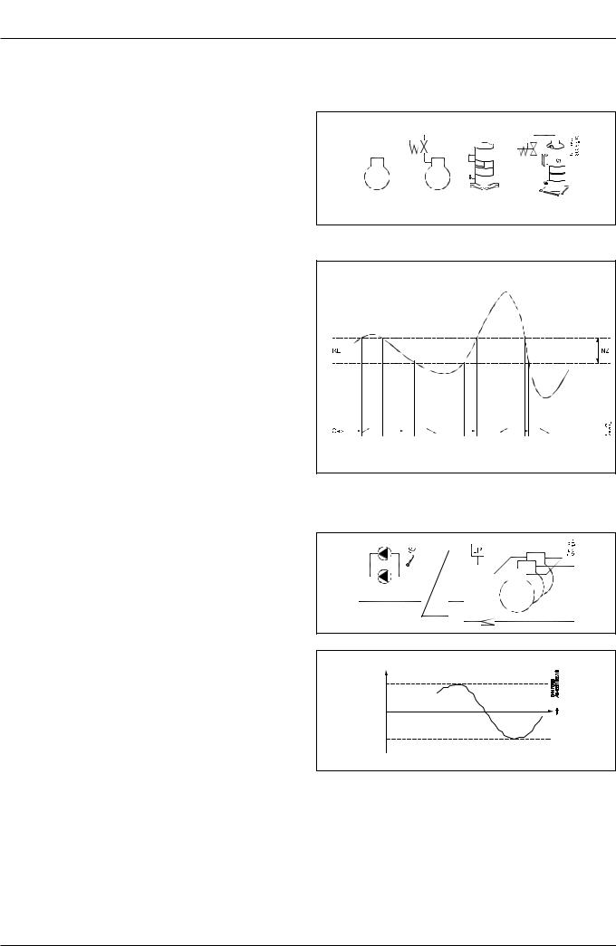
Capacity regulation
The cut-in capacity is controlled by signals from the connected pressure transmitter/temperature sensor and the set reference. Set a neutral zone around the reference .
In the neutral zone the pressure is controlled by the regulating compressor. When it can no longer maintain the pressure within the neutral zone, the controller will cut out or cut in the next compressor in the sequence.
When further capacity is either cut out or cut in, the capacity from the regulating compressor will be modified accordingly to maintain the pressure within the neutral zone (only where the compressor has variable capacity).
–When the pressure is higher than the “reference + a half neutral zone”, cut-in of the next compressor (arrow up) is permitted.
–When the pressure is lower than the “reference - a half neutral zone”, cut-out of a compressor (arrow down) is permitted.
–When the pressure is within the neutral zone, the process will continue with the currently activated compressors.
Control sensor
Normally, a suction group is controlled based on a signal from the Po pressure transmitter.
If control on a brine, the S4 sensor must be the control sensor.
An external, low-pressure switch can be connected to DI7 for frost protection.
The reference
At set or variable reference can be used for regulation. For example, the variable reference can be used for a night time increase or Po optimisation. Enter a set point here so that a contribution from the Po optimisation or night time increase is added. This contribution can raise or lower the reference, as determined by the momentary cooling need.
To limit the reference from values that are too high or too low, set a max. and min. limit.
Po ref.
Max. |
Min. |
AK-PC 351 |
User Guide RS8GZ402 © Danfoss 2017-04 |
3 |
Condenser
Fan control
The fans can be controlled incrementally using the controller’s relays, or they can be speed-controlled via the controller’s analogue output.
Speed control can be via a frequency VLT-type transformer.
If the fans have EC motors, the 0-10 V signal can be used directly.
Control
Regulation is carried out based on a signal from the Pc pressure transmitter or an S7 media temperature sensor. The signal is compared with the regulation reference.
The regulation reference can originate from one or more of the following functions:
•Fixed reference
•Variable reference, which follows the outdoor temperature. When the outdoor temperature drops, the reference will drop by a corresponding amount.
This variable reference requires the installation of an Sc3 outdoor temperature sensor. The sensor must be positioned so that it registers the correct outdoor temperature. In other words, it must be shielded from direct sunlight and located near the airway of the condenser.
This regulation requires setting a min. and max. reference, so that the regulation process is kept within the given limits.
Media temperature
If controlling a media temperature, the control sensor must be set to S7. This temperature sensor must be located in the desired medium.
High-pressure monitoring can occur with an external, high-pres- sure switch on DI8.
Max. ref.
Min. ref.
4 |
User Guide RS8GZ402 © Danfoss 2017-04 |
AK-PC 351 |

Safety functions
Min./max. suction pressure Po
The suction pressure is recorded continuously.
If the measured value falls below the set minimum limit, the compressors will immediately cut out.
If it exceeds the max. value, an alarm will be generated once the time delay has elapsed.
Max. condensing pressure Pc
If the condensing pressure reaches the upper permissible value, the controller will connect all condenser fans to keep the pressure down. At the same time, a portion of the compressor capacity will be disconnected. If the pressure remains near the threshold value, even more compressors will be disconnected.
All compressors will be disconnected immediately if the threshold value is exceeded.
LP switch
On/off signal on a DI7 input
If a signal is received, all compressors will immediately be stopped. When the signal is removed again, the capacity is regulated up again.
HP switch
On/off signal on a DI8 input
If a signal is received, all compressors will immediately be stopped. Fan capacity will increase depending on how much the
Pc measurement exceeds the reference.
When the signal is removed again, the capacity is regulated up again.
Max. discharge gas temperature Sd for digital scroll / stream
Temperature sensor on an AI input.
A signal can be received from a Pt 1000 Ohm sensor on the pressure pipe.
If the temperature nears the set max. temperature, the capacity of the compressor will be increased so that the compressor can cool down itself.
The compressors will be stopped if the temperature reaches up to the set max. temperature value.
Sensor failure
If lack of signal from one of the connected temperature sensors or pressure transmitters is registered an alarm will be given.
•In the event of a Po error (S4 error), regulation will continue with a set capacity in daytime operation (e.g. 50%), and a set capacity in night operation (e.g. 25%), but with a minimum of one step.
•In the event of a Pc error, the condenser capacity that corresponds to how much compressor capacity is connected will cut in. Compressor regulation will remain normal.
•When there is an error on the Sd sensor the safety monitoring of the discharge gas temperature will be discontinued.
•In the event of an error on the outdoor temperature sensor,
Sc3, the permanent setting value will be used as a reference.
NB: A faulty sensor must be OK within 10 minutes before a sensor alarm is cancelled.
General DI alarm
On/off signal on a DI8 input
If the input is used as general alarm input alarm text and delay times can be connected.
Alarm and text will appear when the delay time has elapsed.
AK-PC 351 |
User Guide RS8GZ402 © Danfoss 2017-04 |
5 |

Display overview
End-user overview
The images in this daily user interface will depend on how the set-up is made. They will illustrate what is regulated. For example: One suction group, one condenser group, or a combination. See examples below:
1suction groupe
1condenser group
1suction group and
1condenser group
Press "Enter"
to get to the overview
When an alarm is sent from the controller, you must advance to this
display to see the alarm text.
Select a line and press "Enter"
Status = either 1 suction group or |
1 condenser group |
or |
Both suction group |
|
|
|
and condenser group |
Parameters |
Access to the menus requires pass- |
|
word. |
|
Level 1: Only view (100) |
|
Level 2: Change values (200) |
|
Level 3: Change configuration (300). |
6 |
User Guide RS8GZ402 © Danfoss 2017-04 |
AK-PC 351 |
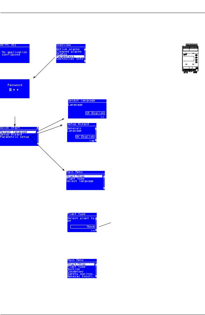
Set-up overview
There are two ways in which the controller can be set up. Select the one that is easiest for you: either “Wizard” or a review of “all parameters”.
Start screen upon delivery
Operating principles
1. Select position using arrow keys
2. Select using “Enter”
3. Use the “X” to return
Press “Enter” |
Hold “Enter” down for 2 sec- |
|
onds to come to password entry |
The default password upon delivery is 300. Use the arrow keys to set the password. End by pressing “Enter”
Wizard
Here you will be led through a series of settings, after which the controller will be ready for start.
Image 1 of 22 is displayed here.
Select a set-up method. End by pressing “Enter”
Main Menu |
|
|
The first setting is the |
The following options are available here: |
|
Plant type |
||
• Comp. + Cond. = suction group and condenser |
||
|
||
|
• Condenser = ondenser only |
|
|
• Compressor = suction group only |
|
|
• None |
|
When the Plant type has |
|
|
been selected, it will al- |
|
|
low several settings to be |
|
|
made. |
|
|
For example: |
|
Continue to the next menus.
All settings are explained on the pages that follow
AK-PC 351 |
User Guide RS8GZ402 © Danfoss 2017-04 |
7 |
 Loading...