


102E7
7-Day electronic mini-programmer
for controlling hot water and heating
(Including Factory Replacement Units FRU)
Danfoss Heating
Installation and User Guide

INDEX
Index
Installation
Product specification |
3 |
Installation |
4-6 |
Wiring |
6-9 |
Replacement |
10-11 |
User |
|
|
|
Your programmer |
12 |
Resetting the unit |
12 |
24hr or AM/PM display |
13 |
Setting the Time and Day |
13 |
Factory preset programmes |
14 |
Changing the preset programmes |
15 |
Setting the programme - 7 day |
16-17 |
Setting the programme - 5/2 day |
18-19 |
Running your programme |
20 |
Temporary user overrides |
21 |
Battery backup |
22 |
Contact details |
24 |
|
|
®
Certification Mark
Danfoss can accept no responsibility for possible errors in catalogues, brochures, and other printed material. All trademarks in this material are property of the respective companies. Danfoss and the Danfoss logotype are trademarks of Danfoss A/S. All rights reserved.
2

Installation Instructions
Please Note:
This product should only be installed by a qualified electrician or competent heating installer, and should be in accordance with the current edition of the IEEE wiring regulations.
Product specification
Specification |
|
|
|
|
|
|
|
Power supply |
230 Vac ± 15%, 50 Hz |
|
|
|
|
|
|
Switching action |
1 x SPST, Type 1B |
|
|
|
|
|
|
Max. Switch rating |
264Vac, 50/60Hz, 3(1)A |
|
|
|
|
|
|
Running/Setting Accuracy |
±1 min./month |
|
|
|
|
cation |
|
Power Reserve |
Minimum 24 hours |
||
|
|||
|
|
|
|
Max. Ambient Temperature |
45°C |
|
|
|
|
Specifi |
|
Design standard |
EN 60730-2-7 |
||
Dimensions, mm (W, H, D) |
102 x 136 x 47 |
|
|
|
|
|
|
Control Pollution Situation |
Degree 2 |
|
|
|
|
|
|
Rated Impulse Voltage |
2.5kV |
|
|
|
|
|
|
Ball Pressure Test |
75°C |
|
|
|
|
|
3

Installation
NB. For FRU units - go straight to point 6 below.
1.Loosen the fixing screw in the base of the unit to release the Wiring Cover.
2.Holding the unit face downwards, press firmly in the centre of the wallplate and slide it apart and lift it from the module.
3.Fix the wallplate and terminal block to the wall, or plaster box, as required. Ensure that the screw heads do not protrude beyond the vertical centre rib of the wallplate, or this will prevent the module correctly locating onto the wallplate.
Screw fixing holes (screwheads MUST NOT protrude above
centre rib) |
Vertical centre rib |
|
Installation
Wallplate & Terminals
4.Surface cables can only enter from below the unit. Cut an appropriate cable aperture in the wiring cover. If the wallplate is mounted on a plaster box, cables can enter from the rear below the terminal block.
4

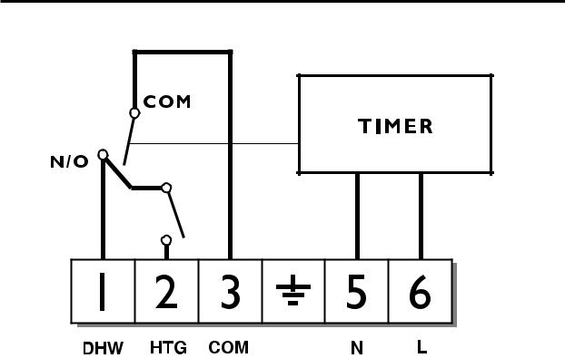
5.Electrical connections are simplified by using a Wiring Centre. However, if this is not used, the wallplate terminal identification is as shown.
Water |
Heating |
|
Mains Supply |
|
||
|
|
COM |
(via 3 amp fuse) |
|
||
ON |
ON |
|
||||
|
|
|
|
|||
|
N |
|
L |
|||
|
|
|
|
|
||
|
|
|
|
|
|
|
1 |
2 |
3 |
|
5 |
|
6 |
|
|
|
|
|
|
|
If the system being controlled is 230Vac then terminals 3 and L must be linked with insulated cable capable of carrying full load current. Whilst the unit does not
require an earth connection, a terminal is provided on the wallplate for earth continuity purposes.
6. |
Referring to the wiring diagrams on page 6-9, connect the |
|
|
unit as shown. |
|
7. |
Find out from the user whether the unit is required to |
|
|
operate in 7-day mode (factory preset) or weekday/ |
|
|
weekend mode (5/2 day). To convert to 5/2 day mode |
|
|
remove the small two-way connector from the pins |
Installation |
|
towards the left of the recess on the rear of the module, |
|
|
|
|
|
then press the button marked R/S under the flap to RESET |
|
|
the unit. |
|
8. |
Ensure all dust and debris are cleared from the area. Plug |
|
|
the module into the wallplate by locating it onto the |
|
|
wallplate and, when flush with it, sliding it down, ensure |
|
|
the hook at the top of the wallplate engages with the slot |
|
|
at the back of the module. |
|
9. |
Before setting the programme, check the unit and circuit. Set |
|
|
the rocker switch to WATER & HEATING. Press the SELECT |
|
|
button until the bar in the display lines up with the word ON. |
|
|
Adjust the remote thermostats to check the system operates |
|
correctly. |
5 |
|
10.Then press the SELECT button until the bar lines up with the word OFF and check the system does not operate.
11.Set the rocker switch to WATER ONLY. Press the SELECT button until the bar in the display lines up with the word ON and check that the water circuit only operates.
12.When the circuit check has been completed, replace the wiring cover and tighten the fixing screw. Cut any cable aperture in the wiring cover which may be necessary to accommodate surface mounted cables.
13.Finally set time of day and programmes required, noting that the unit is supplied with a pre-set programme, as stated on Page 14.
Wiring
Wiring
102, 102E5, 102E7
6
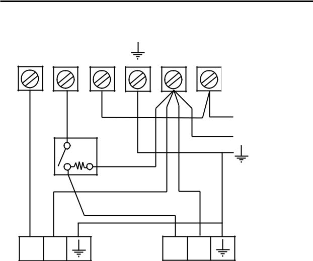
Typical Gravity DHW with Pumped Heating
1 |
2 |
3 |
5 |
|
6 |
|
|
|
|
|
|
|
102E7 |
||
|
|
|
|
|
102E5 |
|
|
|
|
|
|
|
TERMINALSINALS |
||
|
|
LINK |
|
|
L |
|
|
|
|
|
|
|
MAINS |
||
|
COM |
|
|
|
N |
||
|
ROOM |
|
|
SUPPLY |
|||
|
|
|
|
||||
|
|
|
|
|
FUSED |
||
|
|
'STAT |
|
|
|
3 AMP |
|
|
CALL |
N |
|
|
|
|
|
|
|
|
|
|
|
||
L |
N |
BOILER |
L |
N |
PUMP |
||
TERMINALS |
TERMINALS |
||||||
|
|
|
|
||||
Typical domestic gas or oil-fired central heating system with gravity hot water and pumped heating. (If a room thermostat is not used, wire pump live directly to terminal 2 of the 102E7).
Wiring
7
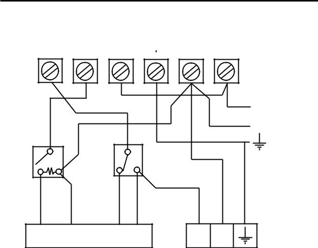
Typical Heating and Hot Water control system using 3-port mid-position valve
1 |
2 |
3 |
|
|
|
|
|
|
5 |
6 |
|
|
|
|
|
|
|||||
|
|
|
|
|
|
|||||
|
|
|
|
|
|
|
|
|
102E7E5 |
||
|
|
|
TERMINALS |
||
|
|
|
LINK |
|
|
|
|
|
L |
|
|
|
|
|
N |
MAINS |
|
ROOM |
|
|
SUPPLY |
||
'STAT |
COM |
CYL. |
COM |
FUSED |
|
3 AMP |
|||||
|
|
'STAT |
|
||
|
|
|
|
||
CALL |
N |
SAT |
CALL |
|
WHITE |
BLUE |
GREY |
RED OR |
|
OR |
|
|||
BROWN |
|
|
ORANGE |
BOILER & |
|
MID-POSITION VALVE |
L N |
||
|
PUMP |
|||
|
|
|
|
TERMINALS |
Wiring
The above control system is available as the Danfoss Randall 102E7 HEATSHARE pack, which also includes the RMT room thermostat, AT cylinder thermostat, HS3 mid-position valve and a WB12 wiring box.
8
 Loading...