


DLP-32G1
Daewoo DLP-32G1, DLP-32G1T, DLP-32G1R, DLP-32G1LPB, DLP-32U1 Service Manual
...
Service Manual
LCD TV
CHASSIS : SL-601P
Model :
S/M NO. : TSL601PEF1
May 2008
DLP-32G1
DLP-32G1P
DLP-32G1R
DLP-32G1T
DLP-32G1W
DLP-32G1LPB
DLP-32U1
DLP-32U1P
DLP-32U1R
DLP-32U1T
DLP-32U1W
DLP-32U1LPB
DLP-32U2
DLP-32U2P
DLP-32U2R
DLP-32U2T
DLP-32U2W
DLP-32U2LPB
DLP-32C5
DLP-32C5P
DLP-32C5PD
DLP-32C7
DLP-32C7P
DLP-32C7PB
BLT-32U10A
(TAGAZ OEM)
DLP-37G1
DLP-37G1P
DLP-37C7
DLP-37C7P
DLP-37C7PB
DLP-42G1
DLP-42G1P
DLP-42C1
DLP-42C1P
DLP-42C5
DLP-42C5P
DLP-42C5PD
DLP-42C7
DLP-42C7P
Contents
1.Safety Precaution 3
2.Product Specification 4
2-1.Product Specification
4
2-2.Available Input Signal 5
3.Block Diagram 6
4.Description of Each Block 7
4-1.Overview 7
4-1-1.SCART1 RGB 8
4-1-2.SCART2_CVBS 9
4-1-3.AV3_S-VIDEO 9
4-1-4.COMPONENT_Y Pb Pr 10
4-1-5.HDMI 11
4-1-6.PC 11
4-1-7.Sound I2S 13
4-1-8.Sound Output 14
4-2.POWER PCB 14
4-2-1.Input Requirements 14
4-2-2.Output Voltage and Current 15
4-2-3.Ripple and Noise 16
4-2-4.Connectors 17
5.SERVICE MODE 19
6.Main PCB Trouble Diagnosis 20
6-1.Main PCB Trouble Diagnosis 20
6-1-1.Common checking process when “No signal or No raster” 20
6-1-2.When No Sound 27
6-1-3.When Control Key does not operate 29
6-1-4.When Remote Controller does not operate 30
6-2.POWER PCB 32
7.Trouble Diagnosis 33
7-1.Facts you must know when Diagnosis or Repairing 33
7-2.Typical Symptoms of PCB problem or bad connection 34
8.Exploded View 35
9.Service Part List 46
10.Circuit Diagram 54
-2-

-3-
1. Safety Precautions
(1) When moving or laying down a LCD Set, please deal with care. Avoid any impact
towards the LCD Set.
(2) Do not leave a broken LCD Set on for a long time. To prevent any further damages,
after check the broken Set’s condition, make sure to turn the power(AC) off.
(3) When opening the BACK COVER, you must turn off power(AC) to prevent any
electric shock.
(4) When loosening screws, check the connecting position and type of the screw. Sort
out the screws and store them separately because screws holding PCBs are
working as electric circuit grounding. Make sure to check if any screw is missing
when assembling.
(5) A LCD Sets contains different kinds of connector cables. When connecting or
disconnecting connector cables, check the direction and position of the cable
beforehand.
(6) When disconnecting connectors unplug the connectors slowly with care.
(7) Connecotrs are designed so that if the number of pins or the direction does not
match, connectors will not fit. When having problem in plugging the connectors,
make sure to check their kind, position and direction.
-4-
2. Product Specification
2-1.PRODUCT SPECIFICATION
Features 32 inch Model 37 inch Model 42 inch Model
LCD Panel
Screen Size 32" 37" 42"
Aspect Ratio 16 : 9 16 : 9 16 : 9
Resolution 1366x768(WXGA) 1366x768(WXGA) 1366x768(WXGA)
Pixel Pitch
170.25um x 510.75um x
RGB
0.200mm x 0.600mm x RGB 0.227mm x 0.681mm x RGB
Contrast Ratio 5000 : 1 5000 : 1 5000 : 1
TV System
Receiving
System
PAL,SECAM, NTSC(AV) PAL,SECAM, NTSC(AV) PAL,SECAM, NTSC(AV)
Stereo
FM MONO / 2-Carrier,
NICAM
FM MONO / 2-Carrier,
NICAM
FM MONO / 2-Carrier,
NICAM
Channel Memory ANALOG : 0~99CH ANALOG : 0~99CH ANALOG : 0~99CH
Input
Connector
RF 75 Ohm Coaxial 75 Ohm Coaxial 75 Ohm Coaxial
S_Video 1 1 1
SCART 2 2 2
Component RCA x 1 RCA x 1 RCA x 1
PC RGB D-Sub x 1 D-Sub x 1 D-Sub x 1
PC Audio 3.5mm Mini-Jack 3.5mm Mini-Jack 3.5mm Mini-Jack
HDMI 2 2 2
Output
Connector
Headphone 3.5mm Mini-Jack 3.5mm Mini-Jack 3.5mm Mini-Jack
Sound Output 9W 9W 9W
Power
Consumption
Max
LPL : 115W
Samsung : 135W
150W 200W
Power Source
110VAC~240VAC,
50~60Hz
110VAC~240VAC,
50~60Hz
110VAC~240VAC,
50~60Hz
Dimension(W x H x D)
G series : 806 x 590 x 260
U series : 806 x 588 x 260
C series : 806 x 628.5 x 240
G series : 940 x 682 x 260
C series : 940 x 720 x 328.7
G series : 1044 x 757 x 345
C series : 1037 x 791 x 329
-5-
Product Specification
2-2.Available Input Signal
2-2-1.HDMI/PC/COMPONENT
2-2-2.VIDEO
Note : '1360(6) x 768' is same with '1280 x 768'(Only different from OSD display)
- PAL, PAL-M, PAL-N
- NTSC, NTSC4.43
- SECAM
Resolution
640 x 480
800 x 600
1024 x 768
1360(6) x 768
(1280 x 768)
720 x 480
720 x 480i
720 x 576i
720 x 576
1280 x 720
1920 x 1080i
V-freg
60Hz
HDMI
O
O
X
72Hz
75Hz
60Hz
72Hz
75Hz
60Hz
70Hz
75Hz
60Hz
75Hz
60Hz
50Hz
50Hz
60Hz
50Hz
60Hz
60Hz
50Hz
O
O
X
O
O
X
O
O
X
O
O
X
O
O
X
O
O
X
O
O
X
O
O
O
O
O
O
O
O
O
O
O
O
O
O
X
X
O
O
X
O
X
X
O
X
X
O
O
X
O
O
X
X
X
PC(D-Sub) Component Standard
VESA Standard
VESA Standard
VESA Standard
VESA Standard
VESA Standard
VESA Standard
-6-
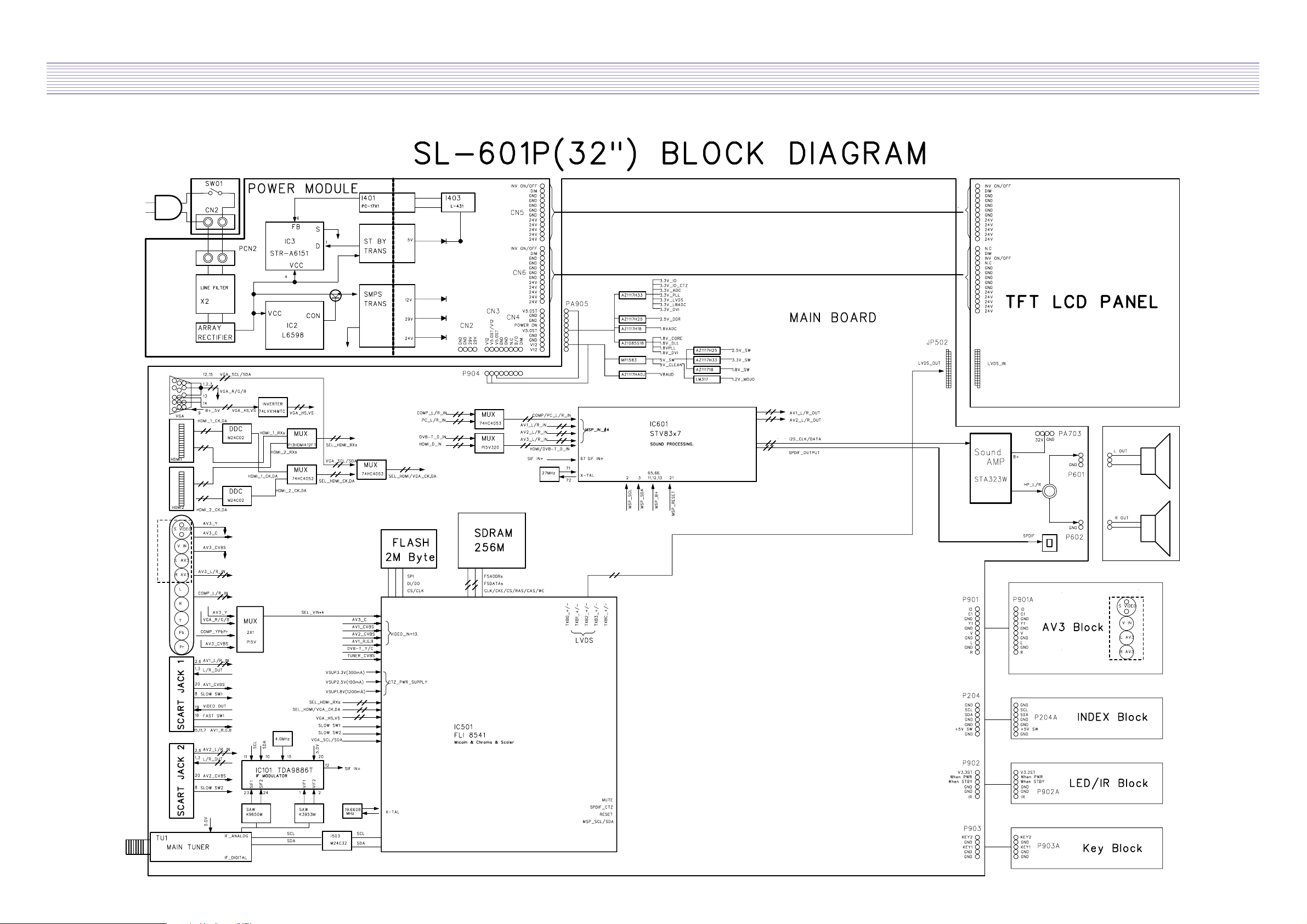
3. Block Diagram
.Block Diagram

-7-
SCART1_RGB
SCART2_CVBS
AV3_SVIDEO
COMPONENT_YPbPr
HDMI1/2
RF
PC
4. Description of Each Block
4-1.Overview
Digital PCB is Multi Media circuit board that can process various input signals such as Video,
Component, PC, HDMI and analog TV signal.
-8-
Description of Each Block
4-1-1. SCART1_RGB
“R signal(input to IC501), LOC : LCA12”
G signal(input to IC501), LOC : LCA11
B signal(input to IC501), LOC : LCA10
-9-
Description of Each Block
4-1-2. SCART2_CVBS
CVBS signal(input to IC501), LOC : CA02
4-1-3. AV3_S-VIDEO
Y signal(input to IC501), LOC : #14 of IC506
Color signal(input to IC501), LOC : RC515
-10-
Description of Each Block
4-1-4. COMPONENT_YPbPr
Y signal(input to IC501), LOC : LCA08
Pb signal(input to IC501), LOC : LCA06
Pr signal(input to IC501), LOC : LCA04
-11-
Description of Each Block
4-1-6. PC
R signal(input to IC501), LOC : LC209
4-1-5. HDMI
HDMI signal(input to IC 501), LOC : RCA31 ~ RCA38, RCA12 ~ RCA19
G signal(input to IC501), LOC : LC207

-12-
Description of Each Block
B signal(input to IC501), LOC : LC205
Horizontal sync(input to IC501), LOC : LC204
Vertical sync9input to IC501), LOC : LC203
-13-
Description of Each Block
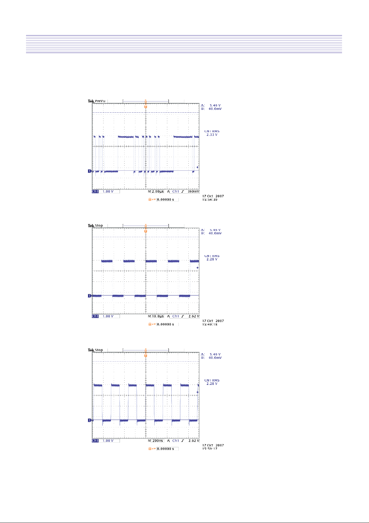
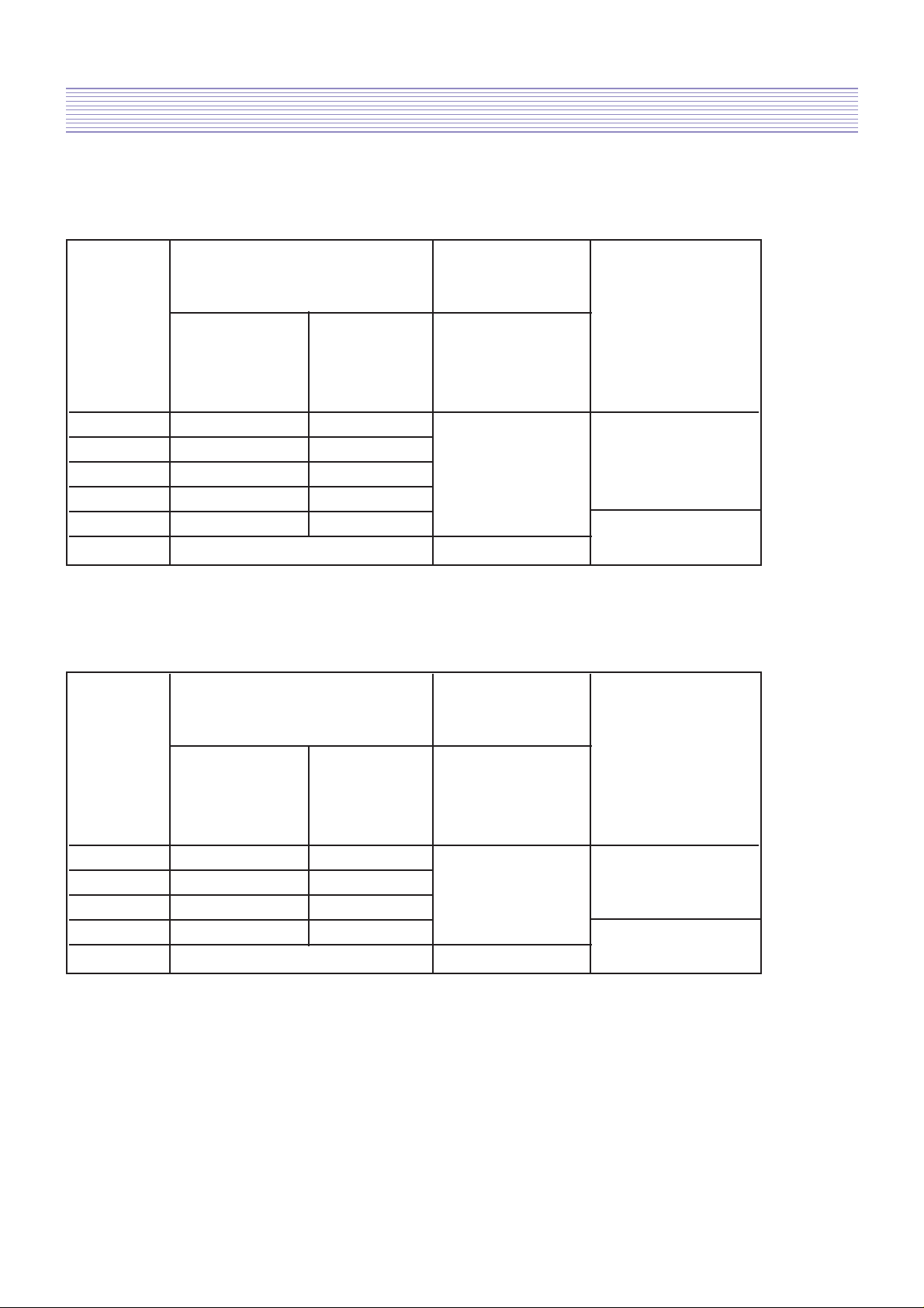
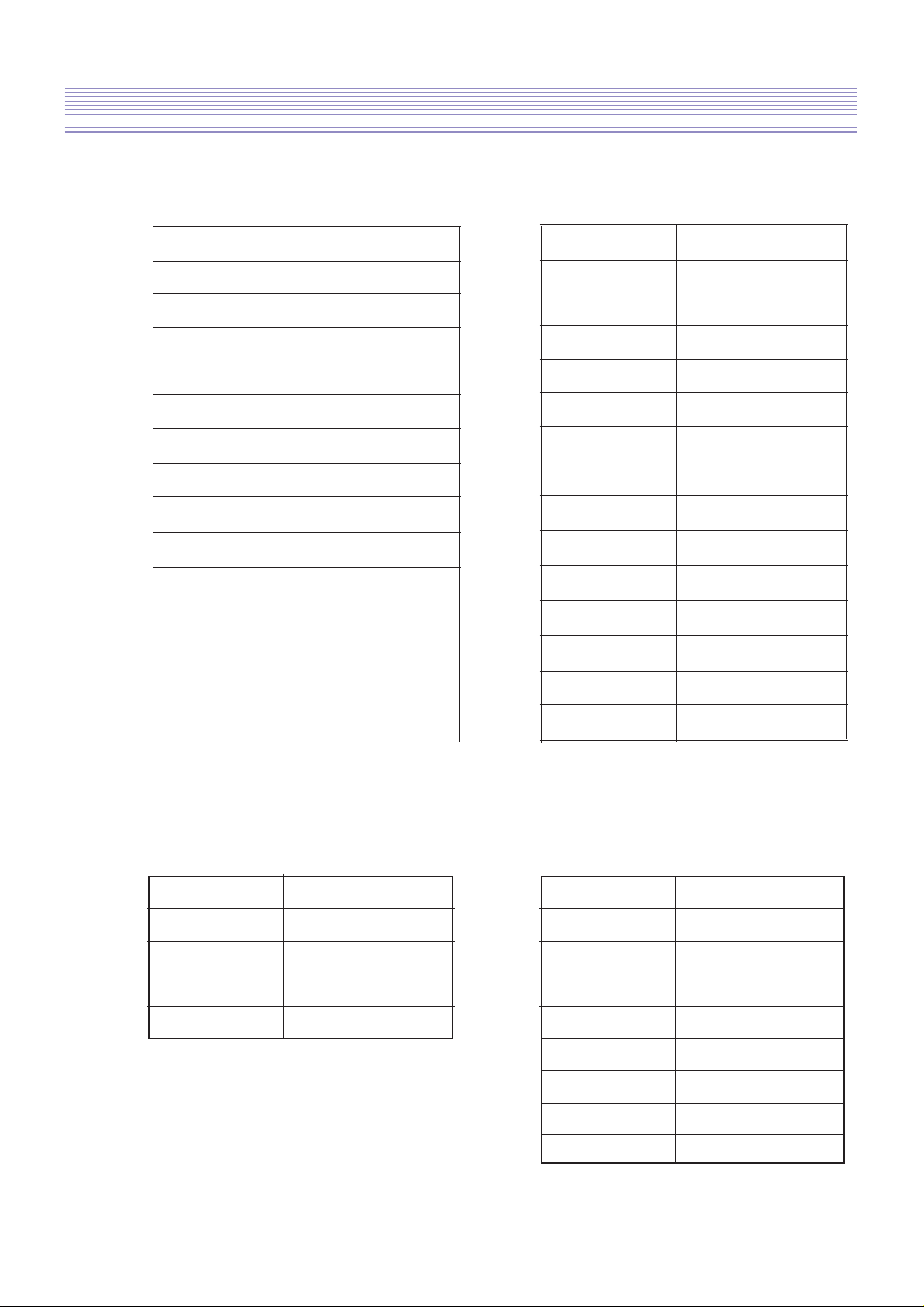
4-1-7. Sound I2S
I2S data(output of IC601), LOC : #30 of IC603
I2S L/R clock(output of IC601), LOC : #31 of IC603
I2S B clock(output of IC601), LOC : #32 of IC603

-14-
Description of Each Block
4-1-8. Sound Output
Speaker Output
4-2. Power PCB
4-2-1. Input Requirements
32” & 37”
42”
Input Voltage Range AC90V ~ 264V
Normal Voltage AC 100V ~ 240V
Normal Frequency 50/60Hz
Input Current < 3.5 Arms at 100 Vac input
< 1.4 Arms at 240 Vac input
Inrush Current 230V 80A peak
Earth Leakage Current 0.5mA MAX(250AC)
Input Voltage Range AC 90V ~ 264V
Normal Voltage AC 110V ~ 240V
Normal Frequency 50/60Hz
Input Current <1.8 Arms at 230 Vac input
Inrush Current 230V 80A peak
Earth Leakage Current 0.5mA MAX(250AC)

-15-
Description of Each Block
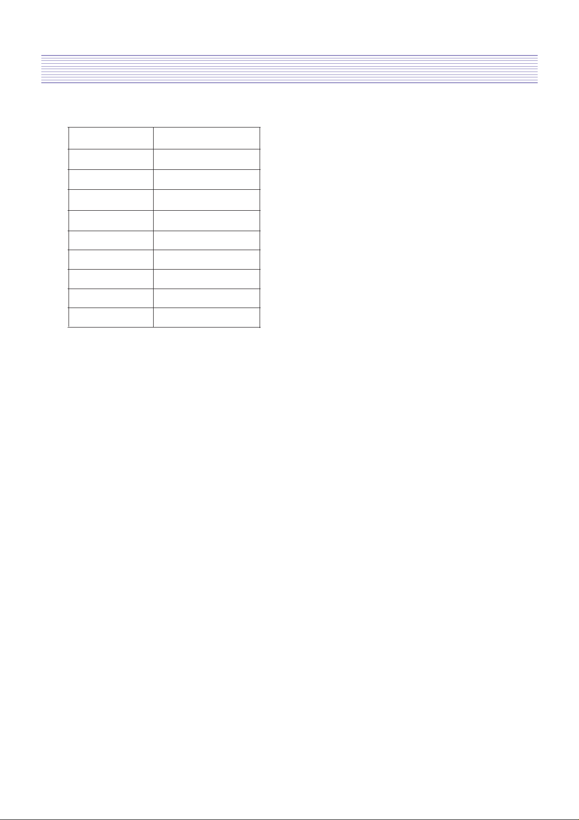
4-2-2. Output Voltage and Current
32” & 37”
42”
Output Munimum Maximum Output Current
Board Voltage Output Output
MIN NOR MAX
Condition
Voltage Voltage
+29Vdc +27.0Vdc +32.0Vdc 0.1A 0.5A 1.0A
+24Vdc +22.3Vdc +25.4Vdc 0.1A 6.0A 7.0A PWR-CTL
DEF +12Vdc +11.00Vdc +12.0Vdc 0.1A 1.5A 2.0A ON
+5Vdc +4.75Vdc +5.25Vdc 0.1A 1.5A 2.5A
ST+5Vdc +4.75Vdc +5.25Vdc 0.1A 0.5A 0.6A PWR-CTL
OFF
Output Munimum Maximum Output Current
Board Voltage Output Output
MIN NOR MAX
Condition
Voltage Voltage
+30Vdc +27.0Vdc +33.0Vdc 0.1A 0.5A 1.0A
+24Vdc +22.3Vdc +25.4Vdc 0.3A 8.0A 9.0A PWR-CTL
DEF +12Vdc +11.00Vdc +12.0Vdc 0.3A 1.2A 2.0A ON
ST+5Vdc +4.75Vdc +5.25Vdc 0.1A 0.2A 0.3A PWR-CTL
OFF
-16-
Description of Each Block
4-2-3. Ripple and Noise
32” & 37”
42”
AC ripple,
Output Voltage Switching ripple
and noise
Output Condition
Name Minimum Maximum
Output Output Continuous
Voltage Voltage
+29V +27.0Vdc +32.0Vdc PWR-CTL
+24V +22.3Vdc +25.4Vdc ON
+12V +11.0Vdc +12.0Vdc 500mVp-p
+5V +4.75Vdc +5.25Vdc MAX LOAD
ST-5V +4.75Vdc +5.25Vdc PWR-CTL
Other Lines Don’t Care OFF
AC ripple,
Output Voltage Switching ripple
and noise
Output Minimum Maximum Condition
Name Output Output
Voltage Voltage Continuous
+30V +27.0Vdc +33.0Vdc PWR-CTL
+24V +22.3Vdc +25.4Vdc 500mVp-p ON
+12V +11.0Vdc +12.0Vdc MAX LOAD
ST-5V +4.75Vdc +5.25Vdc PWR-CTL
Other Lines Don’t Care OFF
-17-
Description of Each Block
4-2-4 Connectors
A. Panel to Power(CN7,CN8) pin spec
B. Power to Main(CN2, CN3, CN4) pin spec
‘New LPL PANEL(WXN Series) have to be
connected on CN8.’
CN7(Old LPL PANEL)
PIN No.
1
2
3
4
5
6
7
8
9
10
11
12
13
14
Output
+24V
+24V
+24V
+24V
+24V
GND
GND
GND
GND
GND
DIMIMING
INV ON/OFF
N/C
GND
PIN No.
1
2
3
4
5
6
7
8
9
10
11
12
13
14
Output
+24V
+24V
+24V
+24V
+24V
GND
GND
GND
GND
GND
INV ON/OFF
CN2 CN3
PIN No.
1
2
3
4
Output
+29V
+29V
GND
GND
CN8(SAMSUNG PANEL)
N/C
DIMIMING
N/C
PIN No.
1
2
3
4
Output
DIMMING
INV ON/OFF
N/C
GND
GND
+5V
+5V
+12V
5
6
7
8
-18-
Description of Each Block
C.CN4
PIN No.
1
2
3
4
Output
+12V
+12V
GND
GND
5
+5V
6
PWR ON/OFF
7
GND
8
GND
9
+5V
 Loading...