


Service Manual
LCD TV
Panel Grade; HD Ready
Buyer Model No.: DLP-37D1
Manufacturer Model No.: LD-3760
DIGITALDEVICE, INC
1
|
Contents |
1. Specifications................................................................................................................................................................................................................................................. |
4 |
1-1. Description. .......................................................................................................................................................................................................................................... |
4 |
1-2. Features................................................................................................................................................................................................................................................ |
4 |
1-3. STRUCTURE AND PRINCIPLE OPERATION OF LCD............................................................................................................................................................................. |
5 |
1-4. General Specification. ............................................................................................................................................................................................................................ |
9 |
1-4-1. Specification. .............................................................................................................................................................................................................................. |
9 |
1-4-2. I/O Description. ......................................................................................................................................................................................................................... |
11 |
1-5. Operation Environmental Conditions....................................................................................................................................................................................................... |
11 |
1-6. Storage Environmental Conditions.......................................................................................................................................................................................................... |
11 |
1-7. Mechanical Test Conditions. .................................................................................................................................................................................................................. |
11 |
2. Block Diagram............................................................................................................................................................................................................................................. |
12 |
2-1. Panel Block Diagram............................................................................................................................................................................................................................ |
12 |
2-2. Connector Layout & Pin Assignment....................................................................................................................................................................................................... |
13 |
2-2-1 PAL & SECAM – SCART. ........................................................................................................................................................................................................... |
13 |
3. Board Assembling. ....................................................................................................................................................................................................................................... |
14 |
3-1. Preparation. ........................................................................................................................................................................................................................................ |
14 |
3-2. Board Assembly Diagram...................................................................................................................................................................................................................... |
15 |
3-2-1 Harness Path Diagram. (PAL/SECAM)........................................................................................................................................................................................... |
15 |
3- 3. Board Sort. ........................................................................................................................................................................................................................................ |
17 |
3-3-1 How to sort Main PCB according to Panel Maker (LG or Samsung). ................................................................................................................................................... |
17 |
3-3-2 How to sort Tuner PCB according to System (PAL, ATSC, 3-System)................................................................ |
..................................................................................18 |
4. Set Assembly................................................................................................................................................................................................................................................ |
19 |
4-1. Assembly Diagram............................................................................................................................................................................................................................... |
19 |
4-1-1. Assemblage of Front Parts. .......................................................................................................................................................................................................... |
19 |
4-1-2. Assemblage of IR. ...................................................................................................................................................................................................................... |
20 |
4-1-3. Sub Panel Assembly.................................................................................................................................................................................................................... |
21 |
|
2 |
|
4-1-4. Assembly of Panel Ass’y.............................................................................................................................................................................................................. |
22 |
|
4-1-5. Assemblage of Board. ................................................................................................................................................................................................................. |
23 |
|
4-1-6. Assemblage of PCB Cover. .......................................................................................................................................................................................................... |
24 |
|
4-1-7. Assemblage of Rear Cover. .......................................................................................................................................................................................................... |
25 |
|
4-1-8. Assemblage of Stand................................................................................................................................................................................................................... |
26 |
4-2. Screw Part Name. ................................................................................................................................................................................................................................ |
27 |
|
4-3. Part List. ............................................................................................................................................................................................................................................ |
29 |
|
5. Trouble Shooting.......................................................................................................................................................................................................................................... |
30 |
|
5-1. Power Failure...................................................................................................................................................................................................................................... |
31 |
|
5-2. |
KEY, LED-IR Control Failure................................................................................................................................................................................................................ |
31 |
5-3. |
Picture Failure..................................................................................................................................................................................................................................... |
32 |
5-4. |
Sound Failure...................................................................................................................................................................................................................................... |
33 |
5-5. Application Failure............................................................................................................................................................................................................................... |
33 |
|
6. Firmware Update Method............................................................................................................................................................................................................................. |
34 |
|
6-1. |
Main Board Firmware Update. ............................................................................................................................................................................................................... |
34 |
3

1. Specifications.
1-1. Description.
The DLP-37D1(37 inch ) is a color active matrix TFT(Thin Film Transistor) LCD(Liquid Crystal Display) that uses amorphous silicon TFT as a switching devices. This model is composed of a TFT LCD panel, a driver circuit and a back light system. The resolution of a 37” contains 1366 x 768 pixels and can display up to 16.7 million colors with wide viewing angle of 170° or higher in all directions.
1-2. Features.
INCH |
37 |
Screen Size(mm) |
37.02 inches(940.3mm) |
Aspect ratio |
16 : 9 |
Resolution |
1366(H) x 768(V) pixels |
Pixel Pitch(mm) |
0.200mm x 0.600mm x RGB |
Pixel Arrangement |
RGB vertical stripe |
Luminance/Brightness |
500 cd/m2 |
Contrast Ratio |
600 : 1 |
Response time(ms) |
8 |
Display Color |
8 bit - 16.7M |
Color Temperature |
|
Viewing Angle |
176(Degrees) |
LCD Size(mm) |
877.0/878.0(H) x 516.8(V) x 55.5(D) |
1-3. STRUCTURE AND PRINCIPLE OPERATION OF LCD.
Basics of LCD Operation
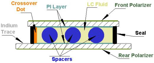
A cross sectional view of a liquid crystal display is shown below in Figure 1. As can be seen in the diagram, the display is simply two pieces of extremely flat glass, over coated with a number of chemical layers, and filled with liquid crystal fluid.
Please notice that this drawing is not made to scale. To give some perspective, the bottom and top glass substrates are typically .043" thick each. The thin film coatings, SiO2, ITO, and PI, are each a few hundred angstroms thick. The space in the middle, marked "LC Fluid", is about 5 microns thick and is adjusted slightly to match the characteristics of the chosen fluid. If this drawing was made to scale, it would be very difficult to see any detail at all between the glass plates.
A liquid crystal display (LCD) is a parallel plate capacitor with a dielectric, in this case the liquid crystal fluid, between the plates. First we select glass coated with a transparent metal coating for the electrodes of the display. The glass is usually made of soda lime, but in some instances it can be a more expensive borosilicate, or because few manufacturers provide borosilicate any more without a fight, aluminasilicate type.
The transparent metal coating can be any thin layer of conductive material, such as gold, silver or tin. In order to keep the cost down and have a reasonable process window with a highly transparent coating, the industry has been using indium-tin oxide (ITO) as the preferred electrode material.
Fig. 1.
5
Photoresist is then put on top of the ITO coating and a photolithographic process is used to image the pattern. The exposed patterns are then developed and the glass is sent through an acid bath where the excess ITO is removed, similar to the way a PC board is made. The remaining photoresist is then stripped away and the patterned segment and common plane electrodes remain on the glass.
The next layer to be applied is the liquid crystal alignment layer. This is usually a polyimide type material and has been chosen for its environmental stability in high moisture and heat. More importantly is its ability to cause the molecules of liquid crystal to align their long axis in the direction in which the polymer has been buffed.
We rub the two halves of the display at right angles to one another and since the liquid crystal molecules like to arrange themselves parallel to one another, we cause a helical structure to be formed between the two electrode faces, see Fig 2 below. This helical structure forms a 90o rotation of the liquid crystal molecules from the top of the display to the bottom.
After the polymer is rubbed, a thermoplastic seal is printed along the perimeter of one piece of glass. This is a resin based material with a high curing temperature, about 200oC, that creates an extremely durable barrier to outside moisture and contamination. Some manufacturers use a UV cured material for this seal as it speeds up the manufacturing process.
We then apply a crossover dot, usually a small spot of silver, to connect the common plane electrode on the top piece of glass to the segment plane which is on the bottom piece of glass. This is somewhat analogous to a plated thru hole on a PC board.
To make the display uniform in appearance, spacers are then applied. These are usually glass or plastic spheres that have the desired diameter to produce a fixed gap between the glass plates. Depending on the liquid crystal used, this gap can be between 4 and 8 microns.
The two halves of the display are then aligned, usually with a three point camera alignment system for accuracy, and brought together. A very thin, uniform, flat and empty bottle has been formed with the thermoplastic seal essentially "gluing" the two pieces of glass together.
A liquid crystal is put inside this bottle by using a vacuum filling technique. The liquid crystal (the dielectric material of our capacitor) is selected for it's various physical properties. The application may call for a liquid crystal fluid that has a very low operating voltage or the display may be used outdoors and require a very wide temperature range. Display manufacturers have developed several liquid crystal mixtures to fulfill most applications.
Once the liquid crystal has been put inside the display and the port opening has been sealed, a polarizer is put on the front of the top glass and a second polarizer is put on the back of the bottom glass to make sure that the light reaching the eye of the observer is oriented along the correct axis.
6

II. Operation of a liquid crystal display.
The liquid crystal molecules are long and thin as shown in Figure 2 on the right. On the bottom glass substrate, the PI layer has been rubbed from back to front, and the molecules are aligned in that direction. Remember, the direction of this orientation determines the viewing angle of the part.
Because the PI layer of the top glass has been rubbed from right to left, the molecules attached to the top piece of glass are oriented perpendicular to the ones at the bottom. This 90o rotation is the "twist" in a twisted nematic display.
Fig. 2
The liquid crystal molecules between the top and bottom glass form a spiral structure that will twist light as it goes through the cell. As can been seen in Figure 3 on the left, a beam of light entering from above passes through the top polarizer along the axis of polarization.
The light beam goes through the cell, and is twisted as it goes in the same direction as the twist of the LC fluid.
The light exits the display, and passes through the polarizer on the bottom glass which is oriented perpendicular to the polarizer on the top.
Fig. 3
7

When a drive signal is applied to the cell electrodes an electric field is set up across the cell. The liquid crystal molecules will "stand up" to align themselves in the direction of the electric field. When the molecules "stand up" the helical structure is disrupted, and the incoming linearly polarized light does not "twist" like it did when the molecules were at rest. The light is instead blocked by the rear polarizer.
Fig. 4
The observer therefore sees a black segment on the clear background. When the electric field is turned off, the molecules relax back to the 90o twist structure, light entering the cell is again twisted 90o and the display returns to a transparent state. This is referred to as a positive image, transmissive viewing mode.
The electro-optic response characteristic of our standard TN cell is asymmetric because only the "turn-on" state can be activated by an electric field. When the RMS voltage goes to zero, the twisted structure, which provides the "twist" of the incident light, is restored by the elastic torques within the LC fluid. We can therefore speed up the "turn-on" time of our display by increasing the drive voltage waveform (over a very limited range), but the "turn-off" time is fixed by the relaxation characteristics of the LC fluid. Nematic liquid crystals exhibit good mechanical shock stability, because they spontaneously return to the uniform alignment after mechanical distortion.
The typical switching times of a TN cell are in the millisecond range, however there are some things we can do to speed things up. This is a topic for long discussions, so if you're interested, please give us a call at 1-440-232-8590 to talk to one of our applications specialists.
8

1-4. General Specification.
1-4-1. Specification.
1-4-1-1. PAL/SECAM.
|
|
HDMI Input & DVI Sound In |
1 |
|
|
|
PC (RGB) |
1 |
|
|
|
Component 1 |
1 |
|
Display Mode |
Input Type |
Component 2 |
1 |
|
AUDIO Line-Out |
1 |
|||
|
|
|||
|
|
SCART Input |
2 |
|
|
|
Power Inlet |
1 |
|
|
|
RS-232C for Service |
1 |
|
|
Video System: PAL/SECAM |
|
|
|
|
Sound System: B/G, D/K, I, L/L’ |
|
|
|
|
FS 181 Program |
|
|
|
TV System |
FVS Tuning (max 100programs) |
|
|
|
Fine Tuning System |
|
|
||
|
|
|
||
|
Auto/Manual Programming/Sorting |
|
|
|
|
1 Tuner (Built-in Tuner) |
|
|
|
|
UHF/VHF/Hyper band |
|
|
|
TV |
Multi-Language OSD |
English,Finland,French,Germany,Spanish,Italian,Portuguese,Dutch,Swedish,Denmark,Norway,Greece,Czech,Hungarian, |
||
Features |
Polish,Russian,Turkish,Arabic,Persian |
|
||
|
|
|||
|
Picture Mode |
TV, Composite, S-Video, Component |
Wide / Panorama / Zoom / 14:9 / 4:3 |
|
|
HDMI, PC |
Wide / Real / 4:3 |
||
|
|
|||
|
Color Temperature |
PC/HDMI/Component |
Normal / Warm1 / Warm2 / Cool1 / Cool2 |
|
|
90˚ Picture Rotation |
NO |
|
|
9

|
Multi-Step Zoom |
NO |
|
|
Sleep Timer |
off ~ 180 minutes |
|
|
Picture in Picture (PIP) with 4 corner position |
||
|
Multi Picture (Twin, PIP, size, Position, Swap) |
||
|
TWIN Window (Picture by Picture) |
|
|
|
Picture Still |
|
|
|
Teletext(No. of pages) |
252 pages |
|
|
Audio Mute |
|
|
|
PC(Analog RGB) |
VGA, SVGA, XGA, SXGA |
|
|
Max. 1280 x 1024 / 60Hz |
||
|
|
||
|
HDMI |
Y/Cb/Cr (Uncompressed) |
|
Input Port |
Max pixel input: 1920 x 1080i |
||
|
|||
|
|
Picture : PAL, NTSC |
|
|
Video Input System |
Audio : PAL,NTSC |
|
|
|
Component - Y.Pb(Cb),Pr(Cr) : 480i ~ 1080i |
|
|
Stereo (A2 / NICAM) / Dual (Mono / Stereo / bilingual) |
||
|
Audio Mode |
Standard / Music / Movie / Speech / Custom |
|
Sound |
Audio Output |
10W Per Channel @ 6 Ohm (Analog) |
|
|
Impedance |
6 Ω(L) + 6 Ω(R) |
|
|
Speaker |
Internal Speaker |
|
Power Source |
Free Voltage |
AC 100~240V 50/60Hz |
|
10

1-4-2. I/O Description.
PAL
1-5. |
Operation Environmental Conditions. |
|
|
|
|
|
Temperature |
0 to 50 °C (with forced-air cooling) |
|||
|
Humidity |
20 to 40 °C |
to 80% RH (without condensation) |
||
1-6. |
Storage Environmental Conditions. |
|
|
|
|
|
Temperature |
-20 to 60 °C |
|
|
|
|
Humidity |
10 to 70% RH (without condensation) |
|||
1-7. |
Mechanical Test Conditions. |
|
|
|
|
|
Vibration (operating) |
4.9m/s2 |
(0.5 |
G), 10 to 100 |
Hz, 3 directions, 10 minutes each |
|
Vibration (non-operating) |
4.9m/s2 |
(0.5 |
G), 10 to 100 |
Hz, 3 directions, 2 hours each |
11
 Loading...