


INTRODUCTION
This manual has been prepared with the assistance of service and engineering specialists to provide you, Daewoo heavy commercial vehicle mechanics, with the information on the electrical equipment of Daewoo heavy duty trucks. We like to assure you that you will be acquainted with more suitable maintenance techniques. It contains a variety of illustrations and diagrams for the electrical equipment to help you easily understand.
Utilizing adequately this manual for you maintenance operations will not only greatly relieve you from unnecessary effort but also enhance maintenance reliability.
Should you have any questions or doubt as to the contents of this manual, do not hesitate to contact us.
Finally, we like to advise you that the specifications and other details on our Daewoo heavy commercial vehicles and are subject to change without prior notice for the purpose of product upgrading, and also we hope that this manual would be of a great help to you in your maintenance operations.
2003. 12
DAEWOO COMMERCIAL VEHICLE CO, LTD
CONTENTS
- DE / DV -
SECTION 1.
GENERAL DESCRIPTIONS .............................................................................................. |
5 |
SECTION 2.
CIRCUIT DIAGRAM BY SYSTEMS............................................................................... |
24 |

1. GENERAL DESCRIPTIONS
SECTION 1
GENERAL DESCRIPTIONS
1. ELECTRIC CIRCUIT DIAGRAM ...................................................................................................... |
6 |
|
1-1. |
HOW TO USE CIRCUIT DIAGRAM |
|
1-2. |
POWER SUPPLY NUMBER |
|
1-3. |
COLOR SYMBOLS FOR WIRING |
|
1-4. |
HOW TO KNOW CONNECTOR PIN NUMBER |
|
2. LOCATIONS OF ELECTRICAL HARNESSES .............................................................................. |
8 |
|
2-1. ROOF / DASH / DOOR HARNESS |
|
|
2-2. FRAME HARNESS (DE/DV) |
|
|
2-3. |
CONNECTOR CONDITION |
|
2-4. |
LOCATIONS OF GROUND CONNECTIONS |
|
2-5. |
FUSE AND RELAY LAYOUT |
|
2-6. |
AUXILIARY FUSE AND RELAY BOX |
|
5

1. GENERAL DESCRIPTIONS
1. ELECTRIC CIRCUIT DIAGRAM
1-1. HOW TO USE CIRCUIT DIAGRAM
A 30
15
15A
15B
58
F31 B
15A
86 30 C
HEAD
LAMP
RELAY
85 87
D
C201
3
HEAD
 LAMP
LAMP
DRIVER ASSIST
G
E
BR
F H
G101
31
CIRCUIT DAIGRAM
LOCATION |
CONTENTS |
|
|
|
|
|
• The power supply line on the circuitry are found in |
|
A |
the upper space of the circuit diagram. |
|
|
• Power supply lines are #30, 15, 15a,15b, 58 |
|
|
|
|
B |
• F31 : Fuse number, 15A : Electric capacity. |
|
|
|
|
C |
• This section shows the parts name and the pin |
|
number. |
||
|
||
|
|
|
|
• This section represents the connector where different |
|
D |
wirings are connected to each other. |
|
C201 indicates the kind of connector, while the #3 |
||
|
||
|
means that it is the third terminal of the connector. |
|
|
|
|
E |
• This section shows the color of the applicable wire. |
|
- BR - : Red stripes on black ground. |
||
|
• This section indicates the location of ground Connection.
F• The bottom line is a battery(-) line or ground(#31). ( G : ground )
•There are a number of cross lines.
A crossing having a dot as in “B A ” means that the
Glines A and B are connected to each other. On the other hand, a crossing having no dot indicates that the lines A and B are separate lines.
H
• This section indicates the body ground Connection. so, there is no wire ground like Gxxx.
1-2. POWER SUPPLY NUMBER
NUMBER |
CONTENTS |
30 • The battery(+) line.
15• Electric power is supplied when the starter switch is turned to the "ON" position before the engine starts.
15A • Electric power is supplied when the starter switch is turned to the "ACC" position.
15B • Electric power is supplied from the starter switch "ON" relay #87.
58 • #58 is switched ON when the head lamp switch is ON.
6
1. GENERAL DESCRIPTIONS
1-3. COLOR SYMBOLS FOR WIRING
• To make it easy to read the circuit diagram, each wiring is given a unique color on the circuit diagram.
EX) |
|
|
|
|
B(black) |
|
R(red) |
|
|
|
Red wiring on black ground |
||||||||
|
|
|
|
|
|
|
|
||||||||||||
|
|
Ground |
|
|
|
|
|
|
|
|
Main color |
|
|
|
|
||||
|
|
|
|
|
|
|
|
|
|
||||||||||
|
|
|
|
|
|
|
|
|
|
|
|||||||||
|
|
SYMBOL |
|
COLOR |
SYMBOL |
|
COLOR |
SYMBOL |
COLOR |
|
|||||||||
|
|
R |
|
|
Red |
|
|
Y |
|
Yellow |
|
L |
Blue |
|
|||||
|
|
B |
|
Black |
|
Lg |
|
Yellowish green |
|
V |
Vilocet |
|
|||||||
|
|
Br |
|
Brown |
|
Gr |
|
Gray |
O |
Orange |
|
||||||||
|
|
W |
|
White |
|
|
G |
|
Green |
|
P |
Pink |
|
||||||
|
|
|
|
|
|
|
|
|
|
|
|
|
|
|
|
|
|
|
|
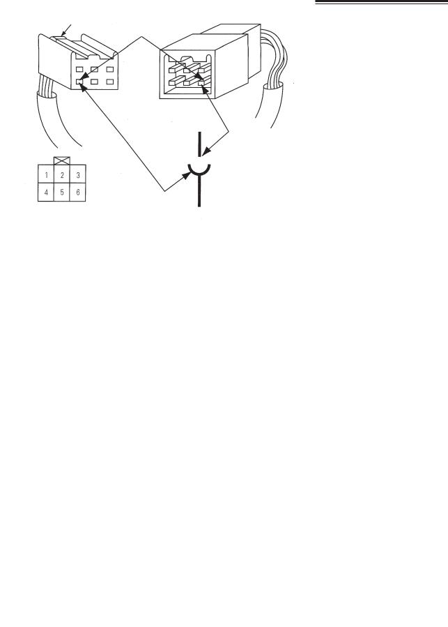
1-4. HOW TO KNOW CONNECTOR PIN NUMBER
1)CONNECTOR PIN FIGURE
Connector pin figure is the total hole number of the connector
2)CONNECTOR PIN NUMBER
EX) NO.4 of the 6 pin connector
LOCKING
NO.4 of the 6-pin connector
MALE CONNECTOR
4
FEMALE CONNECTOR
CXXX
7
1. GENERAL DESCRIPTIONS
2. LOCATIONS OF ELECTRICAL HARNESSES
2-1. ROOF HARNESS/ DASH HARNESS/ DOOR HARNESS
2-1-a. ROOF HARNESS
Mood
Lamp
Air Horn, LH
FRT Speaker, LH
RR Speaker |
H.F.K MIC |
Air Horn, RH
 TR
TR
Clock
Room&Spot Lamp
Large Room Lamp
FRT Speaker, RH
Door switch
Reading
Lamp
RR
Speaker
Cab lock |
|
switch |
Dash Harness |
Dash Harness
Door switch
EL001
8

1. GENERAL DESCRIPTIONS
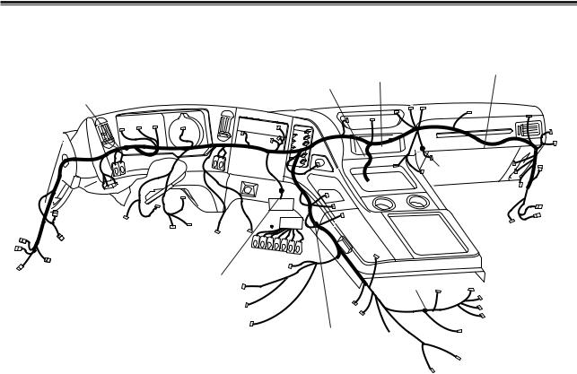
2-1-b. DASH HARNESS (DE/DV)
|
|
|
|
|
|
Customer use Diagnostic |
|
|
|||
|
|
|
|
|
Cassette |
|
|
connector |
Dumping relay |
|
|
|
|
|
|
|
H.F.K Jack |
|
|
Blower |
|
|
|
|
Meter |
|
Tachograph |
Fre&Rec SW |
|
Blower motor |
|
Lift axle relay |
|||
|
Complete |
Speed Meter |
Blower S/W |
A/C SW resistor |
|
Wiper |
Chime bell |
||||
Customer |
|
|
|
|
|
|
|
|
Motor |
One touch |
|
use |
|
|
|
|
|
|
|
|
|
|
|
|
|
|
|
|
|
|
|
|
|
unit |
|
|
|
|
|
|
|
|
|
|
|
|
|
|
|
|
|
|
|
|
|
|
Keyless relay |
Muiti |
|
|
|
|
|
|
|
|
Air heat |
connector |
|||
|
|
|
|
|
|
Cigar |
|
|
|||
|
|
|
|
|
|
unit |
Ignition relay |
|
|||
|
Switch |
|
|
|
Lighter |
|
|||||
|
|
|
|
|
|
Timer |
|
|
|
||
|
|
|
|
|
|
Fuse&Relay |
Q.O.S ECU |
ENG stop relay |
|
||
|
|
|
|
Ignition |
|
(DE12TIS) |
|
||||
Keyless |
|
|
|
|
|
|
|
||||
|
|
S/W |
|
T/M split |
|
|
|
|
|||
entry unit |
|
|
|
|
ZF-T14 Knob |
|
Roof harness |
Door Harness |
|||
Roof harness |
|
|
|
|
|
|
Ashtray ill |
|
C113 |
||
C112 |
|
Split |
Combi |
|
|
|
|
C104-107 |
|||
C111 |
Clutch |
S/W |
|
|
|
|
|
|
|
||
S/W |
|
|
12V outlet |
|
|
|
|||||
|
|
|
|
|
|
|
|||||
|
S/W |
|
|
|
|
|
|
||||
H.F.K MIC |
|
Key hole Stop S/W |
|
Remote |
|
|
|
|
|
||
|
|
|
|
|
|
|
|
||||
|
|
|
Lamp |
|
con kit |
|
|
|
|
|
|
|
|
|
|
|
|
|
|
|
|
||
Dump Control |
|
|
|
Accel S/W Parking S/W |
|
Speed limit unit |
|
|
|||
|
|
|
|
Seat Belt |
|
|
|
|
|||
C101 Door Harness |
|
|
|
|
|
|
|
P.T.OResister ECU-ABS |
|
||
C102 |
|
|
|
Tension Reducer |
|
|
|
|
|||
C103 |
|
|
|
|
|
|
|
|
|
|
|
|
|
|
|
Seat Heater |
Bed Heater |
|
|
|
|
||
|
|
|
|
|
|
Auto grease |
|
|
CPT Customer |
|
|
|
|
|
|
|
|
unit |
DC-DC |
|
|
||
|
|
|
|
|
|
|
|
|
H.F.K Unit |
EL002-1 |
|
|
|
|
|
|
|
|
|
Converter |
|
||
|
|
|
|
|
|
|
|
Noise Filter |
|
||
|
|
|
|
|
|
|
|
|
|
||
ALLISON (AUTO T/M) |
|
|
|
|
|
|
|
|
|
|
|
Cassette |
|
Customer use |
|
Exhaust brake relay |
|||
|
|
|
|
|
|
|
|||
|
|
H.F.K Jack |
|
Blower Diagnostic connector |
|
||||
Meter |
Tachograph |
Fre&Rec SW |
|
motor |
|
|
|
Lift axle relay |
|
Blower S/W |
Blower |
|
|
|
|
|
|||
Complete |
Speed Meter |
A/C SW resistor |
|
|
|
Wiper |
Chime bell |
||
|
|
|
|
||||||
Customer |
|
|
|
|
|
|
|
Motor |
One touch |
use |
|
|
|
|
|
|
|
|
|
|
|
|
|
|
|
|
|
unit |
|
|
|
|
|
Air heat |
|
Oil cooler relay |
Muiti |
||
|
|
|
|
|
connector |
||||
|
|
|
Cigar |
unit |
|
|
|
Keyless relay |
|
|
|
|
|
|
|
Roof harness |
|||
Switch |
|
|
Lighter |
|
TimerECU (DE12TIS) |
||||
|
|
|
Q.O.S |
|
|
Ignition relay |
C113 |
||
|
|
|
|
|
|
|
|
|
|
Keyless |
Ignition |
|
Fuse&Relay |
|
|
|
|
|
|
S/W |
|
Ashtrayill |
|
|
|
|
|
||
entry unit |
|
|
Preselect dowm S/W |
|
|
|
Door Harness |
||
Roof harness |
|
|
|
|
|
||||
|
|
|
VIW-S |
|
|
|
|
||
C112 |
Combi |
|
|
|
|
|
|
C104-107 |
|
|
|
VIM-V Auto T/M |
|
|
|||||
C111 |
S/W |
|
|
|
|
|
|||
|
|
VIM |
|
|
|
|
|
||
|
|
|
|
|
|
|
|
|
|
H.F.K MIC |
Key hole Stop S/W |
|
|
12V outlet |
|
|
|
|
|
Lamp |
|
|
|
|
|
|
|
|
|
|
|
|
|
|
|
|
|
|
|
Dump Control |
Accel S/W Parking S/W |
|
|
|
|
|
|
|
|
|
Seat Belt |
|
Speed limit unit |
|
|
|
|||
|
|
|
|
|
|
||||
C101 Door Harness |
|
|
|
|
Resister |
|
|
||
C102 |
Tension Reducer |
|
|
|
|
|
|||
C103 |
|
|
|
|
Connector |
ECU-ABS |
|
||
|
|
|
|
|
|
|
|
|
|
|
Seat Heater |
Bed Heater |
|
|
|
|
|
|
|
|
|
|
Auto grease |
|
|
|
|
|
|
|
|
|
unit |
DC-DC |
|
|
|
|
|
|
|
|
|
|
|
H.F.K Unit |
|
||
|
|
|
|
Converter |
|
|
EL002-1-1 |
||
|
|
|
|
Noise Filter |
|||||
|
|
|
|
|
|
||||
9

1. GENERAL DESCRIPTIONS
2-1-c. DOOR HARNESS
 Door lock Actuator
Auto Mirror
Power Window Motor
Power Window
Switch
Door Signal Lamp
Dash Harness
EL002-4
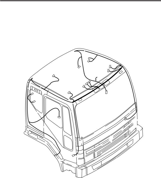
2-2. FRAME HARNESS (DE/DV)
Multi connector
|
Front Combi lamp(RH) |
|
|
|
|
|
|
|
|
||||
|
|
|
|
|
|
|
Ground(110) |
|
|
|
|
||
|
|
|
|
|
|
|
|
Auto mirror |
|
|
|
|
|
|
Head lamp(RH) |
|
|
|
Dual press S/W Cab air sus. M/V |
|
|
||||||
Front |
|
|
|
|
|
|
|
||||||
|
|
|
|
|
Ground |
|
|
|
|
||||
|
|
|
|
|
|
|
|
|
|
|
|
||
Front Combi lamp(LH) |
|
|
|
|
|
|
Sub start S/W |
|
|
|
|||
|
|
Fan |
|
|
|
|
Alternator(DV) |
|
|
|
|||
Head lamp(LH) |
|
|
|
|
|
|
|
Speed limit(DE) |
|
|
|
||
|
|
Washer motor |
|
|
|
|
|
|
|||||
Speed limiter |
|
|
|
|
|
|
Alternator(DE) |
|
|
|
|||
|
Horn |
|
|
|
|
|
|
|
|
||||
|
|
|
|
|
|
|
|
|
|
||||
|
|
|
Compressor |
|
Cab tilt box(DE08/12TIS) |
|
|
||||||
|
|
|
|
|
|
|
Cab tilt box(DV15TIS) |
|
|
||||
|
|
|
|
|
Motor |
|
|
|
|
|
|||
Air compressor |
|
|
|
|
|
Tacho |
P.C.V |
|
|
||||
|
|
|
|
|
Exhaust M/V |
|
|
||||||
(DV15TIS) |
|
|
|
|
|
sensor(DV) |
|
|
|||||
|
|
|
|
|
ENG harness(DE08/12TIS) |
|
|||||||
|
|
ST relay(DV15) |
|
|
|
|
|
Wheel sensor |
|
||||
|
|
|
|
|
|
|
|
|
|
||||
|
|
ST motor(DV15TIS) |
|
|
|
|
Sensor |
P.T.O M/V Auto grease |
|
||||
|
|
|
Air cleaner |
|
|
|
|
ENG(DV15) |
|
Fuel Sensor |
|
||
|
|
|
Air heater relay |
|
|
|
|
Aux fuse box |
|
||||
|
|
|
|
|
|
Ground |
|
P.C.V |
|
||||
|
|
|
|
(DE08/12Tis) |
|
|
|
|
|
||||
|
|
|
|
|
|
|
|
|
|
||||
|
|
|
|
|
ST relay |
|
|
P.C.V |
|
Air master |
Wheel sensor |
||
|
|
|
|
(DE08/12Tis) |
|
|
|
|
Lift axle |
|
|||
|
|
|
|
|
Air tank(FAB) |
(AOH) |
|
||||||
|
|
|
|
|
ST motor |
|
|
||||||
|
|
|
|
|
|
Air master(AOH) |
|
M/V |
RR Combi lamp(RH) |
||||
|
|
|
|
(DE08/12Tis) |
|
||||||||
|
|
|
|
Parking S/W |
|||||||||
|
|
|
|
|
|
|
Back up lamp(RH) |
||||||
|
|
|
|
|
|
|
|
|
Air dryer (FAB) |
P.C.V |
|||
|
|
|
|
|
|
|
|
|
|
||||
|
|
|
|
|
|
|
|
|
|
|
|
Back up buzzer |
Customer use |
|
|
|
|
|
|
|
|
|
|
|
|
|
|
|
|
|
|
|
|
|
|
|
|
Differential |
|
|
License lamp |
|
|
|
|
|
|
|
|
|
|
Wheel sensor |
|
Back up lamp(LH) |
|
|
|
|
|
|
|
|
|
|
|
lock M/V |
|
||
|
|
|
|
|
|
|
|
|
|
|
|
||
RR Combi lamp(LH)
EL005-1
* The location of harness is different by the vehicle type.
10

1. GENERAL DESCRIPTIONS
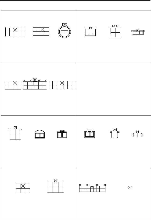
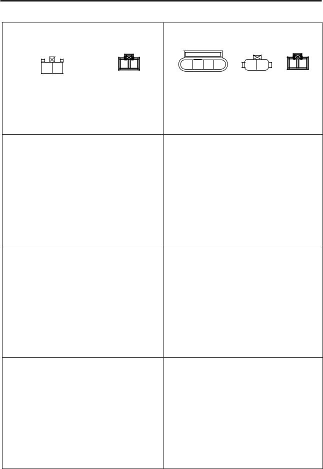
2-3. CONNECTOR CONDITION |
|
|
|
|
|
|
||||
Connector for dash harness and driver's seat door harness |
Connector for dash harness and driver's seat door harness |
|||||||||
1 |
|
4 |
1 |
|
3 |
|
|
2 |
1 |
|
5 |
|
10 |
4 |
|
8 |
|
|
4 |
3 |
|
|
C101(10pin) |
|
C102(8pin) |
|
|
C103(4pin) |
|
|||
|
|
Based on dash harness |
|
|
|
Based on dash harness |
|
|||
Connector for dash harness and assist seat door harness |
Connector for dash harness and assist seat door harness |
|||||||||
1 |
2 |
3 |
|
1 |
2 |
2 |
1 |
|
1 |
2 |
4 |
|
8 |
|
3 |
4 |
4 |
3 |
|
||
|
|
|
|
|
||||||
|
C104(8pin) |
|
C105(4pin) |
C106(4pin) |
C107(2pin) |
|||||
|
|
Based on dash harness |
|
|
|
Based on dash harness |
|
|||
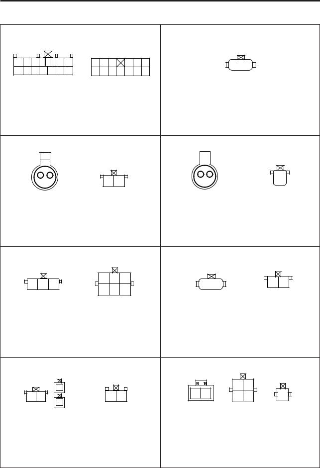
Connector for dash harness and driver's seat roof harness |
Connector for dash harness and assist seat roof harness |
|||||||||
1 |
3 |
1 |
2 |
1 |
3 |
|
|
1 |
4 |
|
4 |
7 |
|
|
5 |
9 |
|
||||
|
|
|
|
|
|
10 |
14 |
|
||
|
|
|
|
|
|
|
|
|
||
C111(7pin) |
C112(2pin) |
|
C114 |
|
|
C113(14pin) |
|
|||
H.F.K MIC |
|
|
|
|||||||
|
|
|
|
|
|
|
|
|
||
|
|
Based on dash harness |
|
|
|
Based on dash harness |
|
|||
|
|
|
|
|
|
|
|
|||
Connector for dash harness and tachograph harness |
Connector for dash harness and switch harness |
|||||||||
|
|
1 |
|
5 |
|
|
1 |
5 |
6 |
10 |
|
|
6 |
|
11 |
|
|
11 |
16 17 |
22 |
|
|
|
C121(11pin) |
|
|
|
|
C131(22pin) |
|
||
|
|
Based on dash harness |
|
|
|
Based on dash harness |
|
|||
|
|
|
|
|
11 |
|
|
|
|
|

1. GENERAL DESCRIPTIONS
Connector for dash harness and frame harness |
Connector for dash harness and frame harness |
|
|
|
|
|
|
|
|
|
|
|
|
|
|
|
|
|
|
|
|
|
|
|
|
|
|
10 |
6 |
|
|
|
5 |
1 |
|
9 |
6 |
|
|
|
5 |
1 |
|
|
|
||||||||
|
|
|
|
|
|
||||||||||||||||||||
22 |
|
17 |
16 |
|
11 |
|
|
|
|
|
|
|
|
|
|
|
|
|
|
|
|||||
|
20 |
|
16 |
15 |
|
10 |
|
||||||||||||||||||
|
|
|
C201(22pin) |
|
|
|
|
|
|
|
|
|
|
|
|
|
|
|
|
|
|||||
|
|
|
|
|
|
|
|
|
C202(20pin) |
|
|
|
|
|
|||||||||||
|
|
|
Based on dash harness |
|
|
|
|
|
|
Based on dash harness |
|
|
|
|
|
||||||||||
|
|
|
|
|
|
|
|
|
|
|
|
|
|
|
|
|
|
|
|
||||||
Connector for dash harness and frame harness |
Connector for dash harness and frame harness |
||||||||||||||||||||||||
|
|
|
|
|
|
|
|
|
|
|
|
|
|
4 |
1 |
1 |
2 |
8 |
5 |
|
|
|
4 |
1 |
|
|
|
8 |
5 |
3 |
4 |
||||
18 |
|
14 |
13 |
|
9 |
|
|
12 |
9 |
||||||||
|
|
|
|
|
|
||||||||||||
|
|
|
C203(18pin) |
|
|
|
|
|
C204(12pin) |
C205(4pin) |
|||||||
|
|
|
|
|
|
|
|
Speed sensor |
|||||||||
|
|
Based on dash harness |
|
|
|
|
|
|
Based on dash harness |
|
|||||||
|
|
|
|
|
|
|
|
|
|
|
|
||||||
Connector for dash harness and frame harness |
Connector for dash harness and frame harness |
||||||||||||||||
2 |
1 |
|
|
1 |
5 |
6 |
10 |
|
2 |
1 |
1 |
||||
4 |
3 |
|
11 |
|
16 17 |
22 |
C206(4pin) |
C207(2pin) |
C208(1pin) |
C209(22pin) |
|
ECM(ABS) |
||||
|
|
|
||
|
Based on dash harness |
|
Based on dash harness |
|
|
|
|
||
|
|
|||
Connector for dash harness and frame harness |
Connector for dash harness and frame harness |
|||
2 |
1 |
1 |
4 |
1 |
3 |
1 |
5 |
6 |
10 |
|
5 |
8 |
4 |
6 |
|||||||
11 |
|
16 17 |
22 |
|||||||
|
|
9 |
12 |
7 |
9 |
|
C210(2pin) |
C211(12pin) |
C212(9pin) |
C213(22pin) |
|
ABS for trailer |
ECM(ABS/ASR) |
|||
|
|
|||
|
Based on dash harness |
|
Based on dash harness |
12
1. GENERAL DESCRIPTIONS
Connector for engine harness and frame harness |
Connector for frame harness and engine harness |
|
|
|
|
|
1 |
4 |
1 |
2 |
|
1 |
|
3 |
|
5 |
8 |
||
|
4 |
|
6 |
|
3 |
4 |
||
|
|
|
9 |
12 |
||||
|
|
|
|
|
||||
C302(6pin) |
C311(12pin) |
C312(4pin) |
||||||
|
Split |
|
|
Speed sensor |
||||
Based on frame harness |
|
Based on frame harness |
|
|||||
|
|
|
|
|
|
|||
Connector for frame harness and trailer harness |
Connector for frame harness and trailer harness |
|||||||
1 |
1 |
2 |
|
|
3 |
4 |
1 |
1 |
|
4 |
3 |
|||
6 |
|
|
|
|
|
|
C401(6pin) |
|
|
|
|
|
|
|
|
|
|
C402(4pin) |
C403(1pin) |
C404(1pin) |
|
|
|
|
|
|
|
|
|
|
|
|
|
|
ABS |
ABS |
|
ABS |
|
|
|
Based on frame harness |
|
Based on frame harness |
|||||||||||||
|
|
|
|
|
|
|
|
|
|
|
|
|
|||||
Connector for frame harness and ABS PCV harness |
Connector for dash harness and instrument harness |
||||||||||||||||
|
|
|
|
|
|
|
|
|
|
|
|
|
|
|
|
|
|
|
|
|
|
|
|
|
|
|
|
|
|
|
|
1 |
8 |
1 |
8 |
|
|
|
|
|
|
|
|
|
|
|
|
|
|
9 |
16 |
9 |
16 |
|
|
|
|
|
|
|
|
|
|
|
|
|
|
|
|
|
B(Black) |
|
1 2 3 |
|
|
|
|
2 1 |
|
|
|
A(White) |
|
|
|||||
|
|
|
|
|
|
|
|
|
|||||||||
|
|
|
|
|
|
|
|
|
|
|
|
1 |
|
|
|
||
P.C.V |
|
C501~504 |
Wheel Speed sensor |
|
|
10 |
|||||||||||
|
|
|
|||||||||||||||
|
11 |
|
|
20 |
|||||||||||||
|
|
|
|
|
|
|
|
|
|
|
|
|
|
|
|
||
|
|
Based on frame harness |
|
C(White) |
|
|
|||||||||||
|
|
|
|
|
|
|
|
|
|
|
|
|
|
|
Based on dash harness |
||
|
|
|
|
|
|
|
|
|
|
|
|
|
|||||
Connector for frame harness and auxiliary fuse box harness |
Connector for frame harness and auxiliary fuse box harness |
||||||||||||||||
1 |
4 |
1 |
1 |
1 |
1 |
5 |
8 |
2 |
|
|
|
|
|
|
|
|
|
C603(1pin) |
C604(1pin) |
C605(1pin) |
|
C601(8pin) |
C602(2pin) |
Trailer ABS Power |
|||
KEY ON Power |
B+ Power |
||||
|
|
: Green |
|
(tractor/Pull Cargo) |
|
|
|
|
: Blue |
||
Based on frame harness |
|
|
|||
|
Based on frame harness |
||||
|
|
|
|||
13

1. GENERAL DESCRIPTIONS
|
|
|
|
|
|
1 |
|
|
1 |
|
|
|
|
8 |
|
|
1 |
|
2 |
|
|
|
|
|
9 |
|
|
|
|
18 |
|
|
|
3 |
|
5 |
|
|
|
2 |
|
|
|
|
|
|
|
|
|
|
|
|
|
|
|
|
|
|
|
|
|
|
|
|
|
|
|
Facia Switch Connector |
|
Customer service/Clutch/ |
|
|
Keyless unit connector |
|
|
|
||||||||
|
|
|
|
|
|
|
|
|
|
|||||||
|
Stop SW/Cigar lighter |
|
|
|
|
|
|
|
|
|
||||||
|
|
|
|
|
|
|
|
|
|
|
|
|
|
|||
|
|
|
|
|
/Seat connector |
|
|
|
|
|
|
|
|
|
|
|
|
|
|
Based on dash harness |
|
|
|
Based on dash harness |
|
|
|||||||
|
|
1 |
2 |
|
1 |
3 |
|
|
|
|
|
|
|
|
|
|
|
|
3 |
4 |
|
4 |
6 |
1 |
|
|
5 |
1 |
3 |
4 |
6 |
1 |
2 |
|
|
|
|
|
|
|
6 |
|
11 |
7 |
|
|
13 |
|||
|
|
|
|
|
|
|
|
|
|
|
|
|||||
Ignition switch |
|
Ignition switch |
|
|
|
|
Combination |
|
Key hole |
|||||||
(Engine stop motor) |
|
(Sub starter) |
Combination |
|
|
|
||||||||||
|
|
|
|
|
|
|
wiper S/W(RH) |
|
|
light S/W(LH) |
|
lamp |
||||
|
|
|
Based on dash harness |
|
|
|
Based on dash harness |
|
|
|
||||||
|
|
|
5 |
|
1 |
Dash |
|
5 |
|
1 |
|
|
|
|
||
|
|
|
11 |
|
6 |
|
|
|
|
|
|
Dash |
||||
|
|
|
|
|
2 |
1 |
11 |
|
6 |
2 |
1 |
|||||
|
|
|
|
|
|
|
|
|
|
|||||||
|
5 |
1 |
5 |
1 |
5 |
1 |
|
|
|
|
|
|
|
|
|
|
"A" |
|
|
"B" |
|
"C" |
Body |
10 |
|
|
|
|
1 |
|
Body |
||
|
|
|
|
|
|
|
|
20 |
|
|
|
|
11 |
|
||
|
8 |
4 |
8 |
4 |
8 |
4 |
|
|
|
|
|
|
|
|
||
|
|
|
|
|
|
|
|
|
|
|
||||||
|
VDO Tachograph connector |
|
CASPO Digital tachograph connector |
|
|
|||||||||||
|
|
|
(behind instrument) |
|
|
|
|
(behind instrument) |
|
|
|
|||||
1 |
3 |
|
1 |
|
2 |
1 |
1 |
|
|
|
|
6 |
|
1 |
|
|
|
|
2 |
|
|
|
|
|
|
|
|
|
|||||
4 |
6 |
|
3 |
|
5 |
3 |
7 |
|
|
|
|
13 |
|
2 |
3 |
|
|
|
4 |
|
|
|
|
|
|
|
|
|
|||||
|
|
|
|
|
|
|
|
One touch unit |
|
DC-DC converter/ |
||||||
Blower switch |
Fre&Rec switch |
|
|
|
ZF-T14 knob/ |
|
||||||||||
Blower resisstor |
|
|
|
|
|
|
||||||||||
|
|
|
|
|
T/M Spliter connector |
|||||||||||
|
|
|
|
|
|
switch |
|
|
|
|
|
|||||
|
|
|
|
|
|
|
|
|
|
|
|
|
|
|
||
|
|
|
Based on dash harness |
|
|
|
Based on dash harness |
|
|
|
||||||
|
|
|
|
|
|
|
|
|
|
|
|
|
||||
|
|
|
|
|
|
|
14 |
|
|
|
|
|
|
|
|
|

1. GENERAL DESCRIPTIONS
|
|
|
|
1 |
|
8 |
1 |
|
|
|
6 |
|
|
|
1 |
|
4 |
|
|
|
|
|
|
|
|
|
|
|
|
|
|
|
|||||||
|
|
|
|
9 |
|
16 |
7 |
|
|
|
12 |
|
|
|
|
|
|||
|
|
|
|
|
|
|
|
|
|
|
|
|
|
|
|||||
|
|
|
|
|
|
|
|
|
|
|
|
|
|
|
|
|
|
||
|
|
|
|
|
Diagnostic connector |
H.F.K unit |
|
|
|
|
H.F.K jack |
||||||||
|
|
|
Based on dash harness |
|
|
|
Based on dash harness |
|
|
|
|||||||||
|
|
|
|
|
|
|
|
|
|
|
|
|
|
|
|
|
|
|
|
|
|
|
|
|
|
|
|
|
|
|
|
|
|
|
|
|
|
|
|
|
|
|
|
|
|
|
|
C1 |
|
|
C2 |
|
C3 |
|
C4 |
||||
|
|
|
|
|
|
|
|
|
1 |
|
|
|
|
|
|
|
|||
|
|
|
|
|
|
|
|
16 |
4 |
1 |
7 |
1 |
13 |
|
1 |
||||
|
|
|
|
|
|
|
|
|
|
|
|
|
|
|
1512 9 6 |
|
|||
|
|
|
|
|
|
|
18 15 12 9 |
6 3 |
|
|
|
9 |
6 3 |
3 |
|||||
|
1 |
2 |
3 |
|
4 |
1 |
4 |
|
6 |
3 |
|||||||||
|
|
|
|
|
|
|
|
|
|
|
|
|
|
|
|
||||
|
|
|
|
|
|
|
|
|
|
|
|
|
|
|
|||||
|
5 |
6 |
7 |
|
8 |
5 |
9 |
ABS/ASR ECM(D-version)connector |
|||||||||||
|
|
|
|
|
|
|
|
|
|
|
|
|
|
||||||
|
|
|
|
|
|
C1 |
|
|
|
|
|
C4 |
|
|
|
||||
|
|
|
|
|
|
|
|
|
|
|
|
|
|
|
|
||||
|
Air heat unit |
Timer Q.O.S unit |
13 |
|
|
1 |
|
|
|
|
16 |
|
1 |
|
|||||
|
|
|
|
|
|
|
|
|
|
|
|
|
|
|
|
|
|
|
|
|
|
|
|
|
|
|
|
15 12 9 |
|
6 3 |
|
|
|
|
18 15 12 9 |
6 3 |
|
||
|
|
|
|
|
|
|
|
|
|
|
|
|
|
|
|
|
|
|
|
|
|
|
|
Based on dash harness |
ABS/ASR ECM(E-Version, D-version basic)connector |
||||||||||||||
|
|
|
|
|
|
|
|
|
|
|
|
|
|
|
|
||||
|
|
|
|
|
|
|
|
|
|
Based on dash harness |
|
|
|
||||||
|
|
|
|
|
|
|
|
|
|
|
|
|
|
|
|
|
|
|
|
87 |
|
|
|
|
a |
b |
c |
d |
e |
f |
|
|
|
|
85 |
|
|
|
86 |
|
|
1 |
2 |
1 2 |
||||||
|
|
|
|
|
|
g |
h |
i j |
k |
l |
m |
|||||
|
|
|
|
|
|
|
|
3 |
5 |
|||||||
|
|
|
|
|
|
|
|
|||||||||
|
|
|
30 |
|
|
|
|
|||||||||
|
|
|
|
|
|
|
|
|
|
|
|
|
|
|||
|
|
|
|
|
|
|
|
|
|
|
|
|
|
|
|
|
|
|
|
|
|
|
|
|
|
|
|
|
|
|
|
|
|
Starter switch "ON"/Keyless |
Chime bell connector |
Wiper motor connector |
Bed-heater |
|||||||||||||
relay connector |
|
|
|
|
|
|
||||||||||
|
|
|
|
|
|
|
|
|
||||||||
(Inside groove box) |
|
|
|
|
|
|
|
|
|
|||||||
|
|
|
|
Based on dash harness |
|
|
|
|
Based on dash harness |
|||||||
1 |
1 |
1 |
1 |
13 |
|
|
|
|
|
1 |
DE12TIS Memory clear |
DE12TIS Diagnostic |
||
26 |
|
|
|
|
|
14 |
connector(Black) |
connector(white) |
||
DE12TIS ECM Frame harness(connector) |
37 |
|
27 |
|||||||
|
|
|||||||||
47 |
|
|
38 |
|||||||
|
|
|
|
|
|
|
|
|
||
|
Based on dash harness |
DE12TIS ECM dash harness(connector) |
||||||||
|
|
|
|
|
|
|
||||
|
|
|
|
|
|
|
Based on dash harness |
|||
15

1. GENERAL DESCRIPTIONS
1 |
4 |
|
|
1 |
3 |
|
1 |
3 |
|
|
1 |
2 |
|
|
5 |
|
8 |
|
4 |
|
6 |
|
|
|
|
||||
|
|
|
|
|
||||||||||
|
|
|
4 |
6 |
|
|
|
|
|
|
||||
|
|
|
|
|
|
|
3 |
4 |
|
|
||||
Wiper intermittent/ |
|
|
|
|
|
|||||||||
|
Key hole lamp unit |
FRT/RR |
Head lamp |
|||||||||||
|
Door lock/ |
|
|
|
|
|
combination lamp |
connector |
||||||
mirror heater unit |
|
|
|
|
|
|
|
|
|
|
|
|
|
|
|
Fuse relay box |
|
|
|
Based on frame harness |
|
|
|
||||||
|
1 |
1 |
2 |
1 |
4 |
|
1 2 |
2 |
3 |
3 |
2 |
|
|||
|
|
|
|
||||
Engine stop motor |
ASR valve connector |
ABS pressure control |
Air dryer |
||||
connector |
|
|
|
|
valve connector |
connector |
|
|
Based on frame harness |
|
|
Based on frame harness |
|||
1 |
2 |
|
|
|
|
|
|
|
|
|
1 |
3 |
1 |
2 |
|
|
|
|
|
|
|
|
|
||||||
1 |
2 |
3 |
1 |
2 |
|
|
||||||||
3 |
4 |
|
|
4 |
8 |
3 |
6 |
|||||||
|
|
|
|
|
|
|
|
|
||||||
Clock |
Room/Spot |
Large room lamp |
Auto mirror |
Mirror heater/ |
||||||||||
connector |
connector |
|
connector |
switch connector |
mirror motor connector |
|||||||||
|
|
Based on roof harness |
|
|
|
|
Based on door harness |
|
||||||
1 |
2 |
1 |
2 |
A |
1 |
|
|
|
|
1 2 |
|||
3 |
4 |
|
|
|
2 |
|
|
|
|
|
|||
Air horn |
Cab lock S/W |
|
Seat belt tension reducer |
Reading/Mood lamp |
||
|
|
|
|
|
/Speaker connector |
|
|
Based on roof harness |
|
|
Based on roof harness |
||
16
1. GENERAL DESCRIPTIONS
|
|
|
|
|
|
|
|
|
|
|
|
|
|
|
|
|
|
|
|
1 |
4 |
1 |
3 |
1 |
3 |
1 |
2 |
1 |
|
|
|
|
2 |
|
4 |
|
3 |
1 |
|
5 |
9 |
4 |
7 |
|
6 |
|
|||
|
4 |
3 |
|
||||||
|
|
|
|
|
|
|
|
Driver seat power |
Assist seat power |
Power window |
Prestroke actuator |
Rack sesnsor NE(Pick-up) sensor |
window switch |
window switch |
motor connector |
& sensor |
|
|
|
|
|
|
|
Based on door harness |
|
DE12TIS Engine |
|
|
|
|
Based on Frame harness |
|
|
|
|
|
|
|
|
|
|
|
|
|
|
|
|
|
|
|
|
|
|
|
|
|
|
|
|
|
|
87 |
|
|
|
|
|
|
|
87 |
|
|
|
|
1 |
3 |
1 |
4 |
1 |
6 |
85 |
|
|
|
86 |
|
|
|
85 |
|
|
|
86 |
|
|
|
|
|
|
|
|
|
|
|
|
|
|
|
|
|
||||||
|
|
30 |
|
|
|
|
|
|
|
30 |
|
|
|
|
||||||
4 |
7 |
5 |
10 |
7 |
13 |
|
|
|
|
|
|
|
|
|
|
|
|
|
||
|
|
|
|
|
|
|
|
|
|
|
|
|
|
|
||||||
|
|
|
|
|
|
|
|
|
|
|
|
|
|
|
||||||
VIW-S |
|
VIW-V |
|
VIM |
Exhaust brake relay |
T/M oil cooler relay |
||||||||||||||
|
Based on dash harness(Auto T/M) |
|
|
|
|
Based on dash harness |
|
|
|
|
|
|||||||||
|
|
|
|
|
|
|
|
|
|
|
|
|
|
|||||||
1 |
2 |
|
|
|
|
2 |
1 |
1 |
|
|
3 |
4 |
2 |
1 |
2 |
1 |
1 |
2 |
|||
|
|
|
|
|
|
|
|
|
||
Auto grease / |
Dual |
Temperature |
Cab tilt motor |
Chime bell |
Cab tilt PBS switch |
|||||
Pump connector |
pressure S/W |
S/W |
|
|
|
|
|
|||
|
Based on frame harness |
|
|
|
|
Cab tilt box |
|
|
||
|
|
|
|
|
Based on frame harness |
|
||||
|
|
|
|
|
|
|
|
|
||
1 |
2 |
1 |
3 |
|
|
|
|
|
|
|
|
|
|
|
|
|
|
|
|
|
|
|
|
|
|
|
|
|
|
|
|
|
4 |
6 |
1 |
|
|
|
|
|
6 |
|
|
1 |
|
|
|
5 |
|
|
|
6 |
|
|
|
|
10 |
||||
3 |
5 |
7 |
|
|
|
|
|
15 |
|
11 |
|
|
|
|
|
|
|
|
|
|
|
|
|
23 |
||||||
Exhaust brake/ |
Auto grease unit |
|
|
PTO Actuator |
|
|
|
|
|
PTO Controler |
|
|
|
|
|
|
||||||||||||||
Preselect down switch |
|
|
|
|
|
|
|
|
|
|
|
|
|
|
|
|
|
|
|
|
|
|
|
|
|
|
|
|
|
|
|
Based on dash harness |
|
|
|
|
|
|
|
Based on dash harness |
|
|
|
|
|
|
|
||||||||||||||
|
|
|
|
|
|
|
|
|
|
|
|
|
|
|
|
|
|
|
|
|
|
|
|
|
|
|
|
|
||
17
1. GENERAL DESCRIPTIONS
|
|
|
|
|
|
|
|
|
|
|
|
|
|
|
|
1 |
|
|
|
|
5 |
1 |
3 |
4 |
6 |
1 |
|
2 |
|
||
|
|
|
|
|
|
||||||||||
6 |
|
|
|
|
12 |
7 |
|
|
13 |
|
|
||||
|
|
|
|
|
|
|
|
|
|
||||||
|
Speed limit unit |
|
|
|
Cassette |
|
Resistor 120 ohm |
|
|||||||
|
|
|
Based on dash harness |
|
|
Based on dash harness |
|
||||||||
|
|
|
|
|
|
|
|
|
|
|
|
|
|||
|
|
|
|
|
|
|
|
|
|
|
|
|
|
|
|
|
|
|
|
|
|
|
|
|
|
|
|
|
|
|
|
1 |
2 |
1 |
1 |
2 |
1 |
|
|
2 |
|
||
|
|
|
|
||
ZF |
|
T14 |
Neutral/ |
Air heater relay |
|
|
Back up lamp |
|
|||
|
|
|
|
||
T/M Split high switch
Based on engine harness
Based on engine harness
1 |
2 |
3 |
1 |
3 |
|
1 |
|
2 |
1 |
2 |
|
|
|
||||||||||
|
|
|
|
|
|||||||
4 |
6 |
|
|
|
|
||||||
|
|
|
|
|
|
|
|
|
|||
Limit switch |
|
|
|
|
Back up/Keyless buzzer |
Back up lamp/ |
|||||
|
Step motor |
|
|||||||||
|
|
|
|
|
|
|
connector |
License lamp |
|||
ESCS actuator connector
Based on frame harness
Based on frame harness
|
3 |
|
|
|
|
1 |
2 |
|
|
|
|
|
1 |
2 |
|
|
|
||
1 |
2 |
1 |
2 |
3 |
4 |
1 |
|||
|
|
||||||||
|
4 |
|
|
A |
|
B |
|
C |
|
|
|
|
|
|
|
||||
Water pump relay |
Preheater relay |
|
|
Switch box |
|
||||
|
|
|
|
|
|
|
|||
Based on frame harness |
Based on frame harness |
|
18
1. GENERAL DESCRIPTIONS
1 2
T/M oil temp switch
2 |
1 |
4 |
1 |
1 |
2 |
T/M oil cooler |
|
Door lock actuator |
|
||
|
|
|
|
||
2 |
1 |
Door turn signal lamp
Based on frame harness |
Based on door harness |
19
1. GENERAL DESCRIPTIONS
2-4. LOCATIONS OF GROUND CONNECTIONS
2-4-a. DASH HARNESS |
G102 |
G100
G101
G104
G106
G105 |
G109 |
|
|
|
G103 |
(+)Power Supply |
(Ground) |
|
|
|
|
|
|
|
|
|
|
EL002-2 |
|||
|
|
|
|
|
|
|
|
|
|
||||||
|
|
|
|
|
|
G100 |
|
|
G101 |
|
|||||
|
|
|
|
|
|
|
|
||||||||
|
|
|
|
|
|
|
|
|
|
|
|
|
|
|
|
|
|
|
|
|
|
|
|
|
|
|
|
|
|
|
|
|
Battery |
|
|
|
|
|
|
|
|
|
|
G102 |
|
||
|
|
|
|
|
|
|
|
|
|
|
|||||
|
|
|
|
|
|
|
|
|
|
|
|
|
|
|
|
|
|
|
|
|
|
|
|
|
|
|
|
|
|
|
|
|
|
|
|
|
|
|
|
|
|
|
|
|
|
G103 |
|
|
|
|
|
|
|
|
|
|
|
|
|
|
|
|
|
|
|
|
|
|
|
|
|
|
|
|
|
|
|
|
|
|
|
|
|
|
|
|
|
|
|
|
|
|
|
|
|
|
|
|
|
|
|
|
|
|
|
|
|
|
|
G104 |
|
|
|
|
|
|
|
|
|
|
|
|
|
|
|
|
|
|
|
|
|
|
|
|
|
|
|
|
|
|
|
|
|
|
|
|
|
|
|
|
|
|
|
|
|
|
|
|
|
|
|
|
|
|
|
|
|
|
|
|
|
|
|
G105 |
|
|
|
|
|
|
|
|
|
|
|
|
|
|
|
|
|
|
|
|
|
|
|
|
|
|
|
|
|
|
|
|
|
|
|
|
|
|
|
|
|
|
|
|
|
|
|
|
|
|
|
|
|
|
|
|
|
|
|
|
|
|
|
G106 |
|
|
|
|
|
|
|
|
|
|
|
|
|
|
|
||
|
|
|
|
|
|
|
|
|
|
|
|
|
|
|
|
|
|
|
|
|
|
|
|
|
|
|
|
|
|
|
|
|
|
|
|
|
|
|
|
|
|
|
|
|
|
G109 |
|
|
|
|
|
|
|
|
|
|
|
|
|
|
|
|
|
|
|
|
|
|
|
|
|
|
|
|
|
|
|
|
|
Ground No |
Location of the ground earth connector wiring |
|
|
G100 |
Near the blower motor |
|
|
G101 |
Near the blower motor |
|
|
G102 |
Near the wiper motor on passenger's side |
|
|
G103 |
Near the bed heater behind the passenger seat |
|
|
G104 |
Near the clutch pedal switch |
|
|
G105 |
Near the switch connector wiring at the right side of the driver's seat |
|
|
G106 |
Near the ECU (DE12TIS) |
|
|
G109 |
Near the PTO unit |
|
|
20

1. GENERAL DESCRIPTIONS
2-4-b. FRAME HARNESS
CAB GROUND
This is located at the right, upper end of the front lid.
It is fastened firmly to the wiper motor housing cover.
FRAME GROUND (DRIVER'S SEAT)
This is located inward the left frame .
It is fasted to the inner frame of the battery
FRAME GROUND (ASSIST SEAT)
This is located inward the right frame : It is fstened to the inner frame of the receiver dryer
AUX. FUSE BOX GROUND
This is located outward the aux fuse box frame.
It is fastened to the outer frame of the aux fuse box.
Battery (-)cable
21

1. GENERAL DESCRIPTIONS
2-5. FUSE AND RELAY LAYOUT
|
|
|
|
|
|
|
|
|
8 7 |
|
|
|
|
|
|
|
|
|
8 7 |
|
|
|
|
|
|
|
|
|
|
8 7 |
||||||||||
|
|
|
|
|
|
|
|
|
|
|
|
|
|
|
|
|
|
|
|
|
|
|
|
|
|
|
|
|
|
|
|
|
|
|
|
|
|
|
|
|
8 5 |
|
|
|
|
|
|
|
|
|
|
8 6 8 5 |
|
|
|
|
|
|
|
|
|
8 6 8 5 |
|
|
|
|
|
|
|
|
|
8 |
6 |
||||||||
|
|
|
|
|
|
|
|
|
|
|
|
|
87a |
|
|
|
87a |
|
|
|
||||||||||||||||||||
|
|
|
|
|
|
|
|
|
|
|
|
|
|
|
|
|
|
|
|
|
|
|
|
|
|
|
|
|
|
|
|
|
|
|
|
|||||
|
|
|
|
|
|
30 |
|
|
|
|
|
|
|
|
|
|
30 |
|
|
|
|
|
|
|
|
|
|
|
|
30 |
|
|
|
|||||||
|
|
|
|
|
|
|
|
|
|
|
|
|
|
|
|
|
|
|
|
|
||||||||||||||||||||
|
|
|
|
|
|
|
|
|
|
|
|
|
|
|
|
|
|
|
|
|
|
|
|
|
|
|
|
|
|
|
|
|
|
|
|
|
|
|
|
|
|
|
Aircon relay |
|
|
|
DBR relay |
Wiper high/low relay |
|
||||||||||||||||||||||||||||||||
|
|
|
|
|
|
|
|
|
8 7 |
|
|
|
|
|
|
|
|
|
8 7 |
|
|
|
|
|
|
|
|
|
|
8 7 |
|
|||||||||
|
|
|
|
|
|
|
|
|
|
|
|
|
|
|
|
|
|
|
|
|
|
|
|
|
|
|
|
|
||||||||||||
|
|
|
|
|
|
|
|
|
|
|
|
|
|
|
|
|
|
|
|
|
|
|
|
|
|
|
|
|
|
|
|
|
|
|
|
|
|
|
|
|
8 5 |
|
|
|
|
|
|
|
|
|
|
8 6 8 5 |
|
|
|
|
|
|
|
|
|
8 6 8 5 |
|
|
|
|
|
|
|
|
|
8 6 |
|||||||||
|
|
|
|
|
|
|
|
|
|
|
|
|
|
|
|
|
|
87a |
|
|
|
|||||||||||||||||||
|
|
|
|
|
|
|
|
|
|
|
|
|
|
|
|
|
|
|
|
|
|
|
|
|
|
|
|
|
|
|
|
|
|
|
|
|
|
|||
|
|
|
|
30 |
|
|
|
|
|
|
|
|
|
|
30 |
|
|
|
|
|
|
|
|
|
|
|
|
30 |
|
|
|
|||||||||
|
|
|
|
|
|
|
|
|
|
|
|
|
|
|
|
|
|
|
|
|
||||||||||||||||||||
|
|
|
|
|
|
|
|
|
|
|
|
|
|
|
|
|
|
|
|
|
|
|
|
|
|
|
|
|
|
|
|
|
|
|
|
|
|
|
|
|
Head lamp low |
relay |
|
Accessory relay |
|
Wiper on/off relay |
|
||||||||||||||||||||||||||||||||||
|
|
|||||||||||||||||||||||||||||||||||||||
|
|
|
|
|
|
|
|
|
8 7 |
|
|
|
|
|
|
|
|
|
8 7 |
|
|
|
|
|
|
|
|
|
|
8 7 |
||||||||||
|
|
|
|
|
|
|
|
|
|
|
|
|
|
|
|
|
|
|
|
|
|
|
|
|
|
|
|
|||||||||||||
|
|
|
|
|
|
|
|
|
|
|
|
|
|
|
|
|
|
|
|
|
|
|
|
|
|
|
|
|
|
|
|
|
|
|
|
|
|
|
|
|
8 5 |
|
|
|
|
|
|
8 6 8 5 |
|
|
|
|
|
|
|
|
|
8 6 8 5 |
|
|
|
|
|
|
|
|
|
8 6 |
|||||||||||||
|
|
|
|
|
|
|
|
|
|
|
|
|
|
|
|
|
|
|
|
|
|
|
|
|||||||||||||||||
|
|
|
|
|
|
|
|
|
|
|
|
|
|
|
|
|
|
|
|
|
|
|
|
|
|
|
|
|
|
|
|
|
|
|
|
|
|
|
|
|
|
|
|
30 |
|
|
|
|
|
|
|
|
|
|
30 |
|
|
|
|
|
|
|
|
|
|
|
|
30 |
|
|
|
||||||||||
|
|
|
|
|
|
|
|
|
|
|
|
|
|
|
|
|
|
|
|
|
||||||||||||||||||||
|
|
|
|
|
|
|
|
|
|
|
|
|
|
|
|
|
|
|
|
|
|
|
|
|
|
|
|
|
|
|
|
|
|
|
|
|
|
|
|
|
|
|
Horn relay |
|
|
|
Converter relay |
|
|
|
|
DE/DV(ECU) |
|||||||||||||||||||||||||||||
|
|
|
|
|
|
|
|
|
8 7 |
|
|
|
|
|
|
|
|
|
8 7 |
|
|
|
|
|
|
|
|
|
|
8 7 |
||||||||||
|
|
|
|
|
|
|
|
|
|
|
|
|
|
|
|
|
|
|
|
|
|
|
|
|
|
|
|
|||||||||||||
|
|
|
|
|
|
|
|
|
|
|
|
|
|
|
|
|
|
|
|
|
|
|
|
|
|
|
|
|
|
|
|
|
|
|
|
|
|
|
|
|
8 5 |
|
|
|
|
|
|
|
|
|
|
8 6 8 5 |
|
|
|
|
|
|
|
|
|
8 6 8 5 |
|
|
|
|
|
|
|
|
|
8 6 |
|||||||||
|
|
|
|
|
|
|
|
|
|
|
|
|
|
|
|
|
|
|
|
|
|
|
|
|||||||||||||||||
|
|
|
|
|
|
|
|
|
|
|
|
|
|
|
|
|
|
|
|
|
|
|
|
|
|
|
|
|
|
|
|
|
|
|
|
|
|
|
|
|
|
|
|
|
|
|
|
|
30 |
|
|
|
|
|
|
|
|
|
|
30 |
|
|
|
|
|
|
|
|
|
|
|
|
30 |
|
|
|
|||||
|
|
|
|
|
|
|
|
|
|
|
|
|
|
|
|
|
|
|
|
|
|
|
|
|
|
|
|
|
|
|
|
|
|
|
|
|
|
|
|
|
Head lamp high relay |
|
Front fog lamp relay |
|
|
Tail lamp relay |
|||||||||||||||||||||||||||||||||||
|
|
|
|
|
|
|
|
|
|
|
|
|
|
|
|
|
|
|
|
|
|
|
|
|
|
|
|
|
|
|
|
|
|
|
|
|
|
|
|
|
|
|
|
|
|
|
|
|
|
|
|
|
|
|
|
|
|
|
|
|
|
|
|
|
|
|
|
|
|
|
|
|
|
|
|
|
|
|
|
|
|
|
|
|
|
|
|
|
|
|
|
|
|
|
|
|
|
|
|
|
|
|
|
|
|
|
|
|
|
|
|
|
|
|
|
|
|
|
|
|
|
|
|
|
|
|
|
|
|
|
|
|
|
|
|
|
|
|
|
|
|
|
|
|
|
|
|
|
|
|
|
|
|
|
|
|
|
|
|
|
|
|
|
10A 15A 20A 30A
1 |
15A |
2 |
10A |
3 |
15A |
4 |
10A |
5 |
10A |
6 |
10A |
7 |
10A |
8 |
15A |
9 |
15A |
10 |
10A |
11 |
20A |
12 |
10A |
23 |
|
|
8 7 |
|
13 |
10A |
24 |
10A |
8 5 |
8 7a 8 6 |
|
14 |
10A |
25 |
|
30 |
||
10A |
5A |
Back up lamp |
||||
15 |
26 |
|||||
16 |
10A |
27 |
5A |
8 5 |
8 7 |
|
|
15A |
|
15A |
8 6 |
||
17 |
28 |
|
30 |
|||
18 |
20A |
29 |
20A |
|
Blinker unit |
|
19 |
10A |
30 |
5A |
|
8 7 |
|
20 |
10A |
31 |
15A |
8 5 |
8 6 |
|
21 |
10A |
32 |
15A |
|
30 |
|
Working relay |
||||||
22 |
10A |
33 |
10A |
|||
|
8 7 |
|||||
|
|
|
|
|
||
|
|
|
|
8 5 |
8 6 |
|
|
|
|
|
|
30 |
|
stop lamp relay
Wiper intermittent control relay Key hole lamp unit Auto door lock mirror heater unit
FuseCapa- |
Description |
Fuse |
Capa- |
Description |
||
No |
city |
No |
city |
|||
|
|
|||||
F1 |
15A |
Ignition switch, Meter, Tachograph |
F18 |
20A |
Air con, Blower motor, Fre & Rec SW |
|
|
|
|
|
|
|
|
F2 |
10A |
Large Room lamp, Door step lamp, Keyhole unit, Diagnosis |
F19 |
10A |
Cab tilt, Cab lock SW |
|
|
|
|
|
|
|
|
F3 |
15A |
DC-DC converter |
F20 |
10A |
Preheater U, Key hole lamp, Seat belt |
|
|
|
|
|
|
|
|
F4 |
10A |
Clock(B+),Cassette(B+),Noise Fitter |
F21 |
10A |
Cassette, clock, Hands free kit unit |
|
|
|
|
|
|
|
|
F5 |
10A |
Engine stop motor, Key box |
F22 |
10A |
Bed heater, Cigar, Seat heater |
|
|
|
|
|
|
|
|
F6 |
15A |
ABS C1-8(ABS/ASR:10A, ABS:15A) |
F23 |
|
T/M oil cooler(Auto T/M), Customer service |
|
|
|
|
|
|
|
|
F7 |
10A |
ABS C1-9 |
F24 |
|
Customer service |
|
|
|
|
|
|
|
|
F8 |
15A |
Blinker unit |
F25 |
10A |
Auto grease unit |
|
|
|
|
|
|
|
|
F9 |
15A |
Door lock,Horn,Keyless,Keyhole lamp,Auto T/M(E-module) |
F26 |
5A |
ABS C1-7, DBR Relay |
|
|
|
|
|
|
|
|
F10 |
10A |
Fog lamp relay |
F27 |
5A |
Trailer ABS(IGN+) |
|
|
|
|
|
|
|
|
F11 |
20A |
Dual one touch unit |
F28 |
15A |
Wiper system, Combi SW |
|
|
|
|
|
|
|
|
F12 |
10A |
Power window switch, Mirror heater unit/switch |
F29 |
20A |
DE12TIS Power R #30 |
|
|
|
|
|
|
|
|
F13 |
10A |
PTO, Diff lock(L/R), Split, Dump control, Lift axle, ELM |
F30 |
5A |
ECM memory clear C, Prest R, ECM Power |
|
|
|
|
|
|
|
|
F14 |
15A |
Differential lock(F/R), ZF-T14 Knob, Lock brake SW, Buzzer unit |
|
|
R #85 Air heater R(DE12TIS) |
|
|
|
|
|
|
|
|
F15 |
10A |
Stop lamp, Auxiliary fuse box |
F31 |
15A |
Head lamp high R #30/85 |
|
|
|
|
|
|
|
|
F16 |
10A |
Reverse R/S, Water pump switch |
F32 |
15A |
Head lamp low R #30/85 |
|
|
|
|
|
|
|
|
F17 |
15A |
Working lamp switch/relay |
F33 |
10A |
Tail lamp R #30/85 |
|
|
|
|
|
|
|
|
22
1. GENERAL DESCRIPTIONS
2-6. AUXILIARY FUSE AND RELAY BOX
Fan motor relay
8 7
85 |
|
|
|
86 |
|
|
|
|
|
30
|
Parking lamp relay |
6 |
5 |
4 |
3 |
2 |
1 |
30A |
86 |
||||||
7 |
|
|
|
|
|
|
|
30A |
30 8 7 85 |
|
|
|
|
|
|
8 |
Rear fog lamp relay |
|
|
|
|
|
|
|
85 |
|
|
|
|
|
|
15A |
|
|
|
|
|
|
|
9 |
86 8 730 |
|
|
|
|
|
|
|
|
50A |
50A |
20A |
30A |
|
FuseCapa- |
Description |
Fuse |
Capa- |
|
Description |
|
No |
city |
No |
city |
|
||
|
|
|
||||
1 |
|
|
6 |
|
|
|
|
|
|
|
|
|
|
2 |
30(A) |
The room fuse #31 - #33 B+(light) |
7 |
30(A) |
Cab tilt box B+ |
|
|
|
|
|
|
|
|
3 |
20(A) |
Trailer ABS B+ |
8 |
30(A) |
Mixer switch box B+ |
|
|
|
|
|
|
|
|
4 |
50(A) |
Starter switch "IG" relay #30 |
9 |
15(A) |
Condenser fan motor relay #30 |
|
|
|
|
|
|
|
|
5 |
50(A) |
The room fuse #1 - #11,23,24 B+ |
|
|
|
|
|
|
Accessary Relay #30 |
|
|
|
|
|
|
|
|
|
|
|
2-7. THE OTHERS RELAY
1.IG relay
2.Keyless relay
3.Engine stop relay
4.Lift axle relay
5.Dumping relay
er
23

2. CIRCUIT DIAGRAM BY SYSTEMS CONTENTS
SECTION 2
CIRCUIT DIAGRAMS BY SYSTEMS
1. STARTER MOTOR AND STARTER SWITCH "ACC" CIRCUIT DIAGRAM......................... |
26 |
2.CHARGING AND STARTER SWITCH "ON" /ENGINE STOP MOTOR CIRCUIT DIAGRAM28
3. |
LIGHT CIRCUIT DIAGRAM ....................................................................................................... |
30 |
4. |
HEATING SYSTEM CIRCUIT DIAGRAM ................................................................................. |
32 |
5. |
12V CONVERTER, CIGAR LIGHTER, BED HEATER, SEAT HEATER CIRCUIT DIAGRAM ............ |
34 |
6. |
BACK UP LAMP CIRCUIT DIAGRAM ..................................................................................... |
36 |
7. |
CAB TILT (MECHANIC), CHIME BELL CIRCUIT DIAGRAM ................................................. |
38 |
8. |
CAB TILT (HYDRAULIC), CHIME BELL CIRCUIT DIAGRAM ............................................... |
40 |
9. |
P.T.O, FOG LAMP CIRCUIT DIAGRAM .................................................................................. |
42 |
10. |
STOP LAMP, TRAILER STOP LAMP CIRCUIT DIAGRAM ................................................... |
44 |
11. |
CLEARANCE, LICENSE PLATE, ASHTRAY, AIR HORN LAMP CIRCUIT DIAGRAM ....... |
46 |
12. |
PARKING LAMP CIRCUIT DIAGRAM ..................................................................................... |
48 |
13. |
SEAT BELT TENSION REDUCER, STEP LAMP, LARGE ROOM LAMP, READING/ |
|
|
MOOD LAMP CIRCUIT DIAGRAM ........................................................................................... |
50 |
14. |
KEY HOLE ILLUMINATION LAMP, ROOM & SPOT LAMP CIRCUIT DIAGRAM ............... |
52 |
15. |
TURN SIGNAL LAMP, HAZARD WARNING LAMP CIRCUIT DIAGRAM............................. |
54 |
16. |
CORNERING LAMP, AUTO GREASE CIRCUIT DIAGRAM .................................................. |
56 |
17. |
CASSETTE, DIGITAL CLOCK CIRCUIT DIAGRAM ............................................................... |
58 |
18. |
DOOR LOCKING DEVICE, HORN CIRCUIT DIAGRAM......................................................... |
60 |
19. |
KEYLESS ENTRY SYSTEM CIRCUIT DIAGRAM ................................................................... |
62 |
20. |
EXHAUST BRAKE, DBR CIRCUIT DIAGRAM ........................................................................ |
64 |
21. |
SPLIT SYSTEM(ZF T/M, T-14 T/M) CIRCUIT DIAGRAM....................................................... |
66 |
22. |
POWER WINDOW CIRCUIT DIAGRAM ................................................................................... |
68 |
23. |
WIPER CIRCUIT DIAGRAM ...................................................................................................... |
70 |
24. |
AUTO MIRROR AND MIRROR HEATER CIRCUIT DIAGRAM .............................................. |
72 |
25. |
TACHOGRAPH CIRCUIT DIAGRAM (VDO, CASPO)............................................................. |
74 |
26. |
HEATER, AIR CONDITIONER CIRCUIT DIAGRAM ............................................................... |
76 |
27. |
SPEED LIMITER CIRCUIT DIAGRAM...................................................................................... |
78 |
28. |
LOCK BRAKE, DIFFERENTIAL LOCK CIRCUIT DIAGRAM |
|
|
(EXCEPT HUB REDUCTION) .................................................................................................... |
80 |
29. |
DIFFERENTIAL LOCK(HUB REDUCTION) CIRCUIT DIAGRAM .......................................... |
82 |
24

2. CIRCUIT DIAGRAM BYCONTENTSYSTEMS
30. |
WATER PUMP-MIXER DRUM CIRCUIT DIAGRAM................................................................ |
84 |
31. |
WORKING LAMP, AIR DRYER HEATER CIRCUIT DIAGRAM .............................................. |
86 |
32. |
TRAILER CONNECTOR CIRCUIT DIAGRAM ......................................................................... |
88 |
33. |
LIFT AXLE CIRCUIT DIAGRAM .......................................................................................................... |
90 |
34. |
ABS/ASR ELECTRIC CIRCUIT DIAGRAM(D-VERSION) ....................................................... |
92 |
|
34-1. ABS/ASR PRESSURE CONTROL VALVE, WHEEL SPEED SENSOR CIRCUIT DIAGRAM |
|
|
(4 SENSOR / 4 CHANNEL) ............................................................................................. |
94 |
|
34-2. ABS/ASR PRESSURE CONTROL VALVE, WHEEL SPEED SENSOR CIRCUIT DIAGRAM |
|
|
(4 SENSOR / 3 CHANNEL) ............................................................................................. |
96 |
35. |
ABS ELECTRIC CIRCUIT DIAGRAM(D-VERSION BASIC) ................................................... |
98 |
|
35-1. ABS PRESSURE CONTROL VALVE, WHEEL SPEED SENSOR CIRCUIT DIAGRAM . 100 |
|
36. |
TRAILER ABS CIRCUIT DIAGRAM ....................................................................................... |
102 |
37. |
ABS BLINKCODE DESCRIPTION .......................................................................................... |
104 |
38. |
SERVICE ELECTRIC EQUIPMENTS FOR USER CIRCUIT DIAGRAM ............................... |
110 |
39. |
DE12TIS ECM POWER, RACK SENSOR, RPM SENSOR CIRCUIT DIAGRAM ................ |
112 |
40. |
DE12TIS DIAGNOSTIC, PREST SENSOR AND ACTUATOR CIRCUIT DIAGRAM ........... |
114 |
41. |
INSTRUMENT SYSTEM CIRCUIT DIAGRAM ........................................................................ |
116 |
|
41-1. INSTRUMENT SYSTEM FOR DE ENGINE CIRDUIT DIAGRAM................................ |
116 |
|
41-2. INSTRUMENT SYSTEM FOR DV ENGINE CIRDUIT DIAGRAM................................ |
118 |
|
41-3. INDICATOR LAMP OF INSTRUMENT CIRCUIT DIAGRAM |
|
|
(PREHEAT, LIFT AXLE, CAB TILT ETC) .................................................................... |
120 |
|
41-4. INDICATOR LAMP OF INSTRUMENT CIRCUIT DIAGRAM |
|
|
(PTO LAMP, DIFFERENTIAL LOCK LAMP ETC) ...................................................... |
122 |
|
41-5. SWITCH AND WARNING LAMP CIRCUIT DIAGRAM ............................................... |
123 |
|
41-5-1. SWITCH AND WARNING LAMP CIRCUIT DIAGRAM(FOR A.O.H).............. |
124 |
|
41-5-2. SWITCH AND WARNING LAMP CIRCUIT DIAGRAM(FOR F.A.B) .............. |
125 |
|
41-5-3. SWITCH AND WARNING LAMP CIRCUIT DIAGRAM ................................... |
126 |
42. |
HANDS FREE KIT CIRCUIT DIAGRAM................................................................................. |
128 |
43. |
ENGINE SPEED CONTROL SYSTEM (ESCS)...................................................................... |
130 |
|
43-1. ENGINE SPEED CONTROL SYSTEM(ESCS) ............................................................. |
132 |
44. |
OIL COOLER CIRCUIT DIAGRAM(ALLISON AUTO TRANSMISSION) .............................. |
134 |
|
44-1. AUTO TRANSMISSION OIL COOLER CIRCUIT DIAGRAM ....................................... |
134 |
|
44-2. AUTO TRANSMISSION OIL COOLER CIRCUIT DIAGRAM ....................................... |
136 |
25

2.CIRCUIT DIAGRAM BY SYSTEMS
1.STARTER MOTOR AND STARTER SWITCH "ACC" CIRCUIT DIAGRAM
|
|
|
|
|
|
|
30(Fuse box #1-#11) |
|
|
|
|
|
|
||
|
|
|
|
|
|
|
15a (Fuse box #21-#22) |
|
|
|
F1 |
|
|||
|
|
|
|
|
|||
|
|
|
|
|
|
1.Tachograph |
|
|
15A |
|
|||||
|
|
2. Instrument panel A-4 |
|||||
|
|
|
|
|
|
||
|
|
|
|
|
|
|
|
|
|
|
|
|
|
|
|
|
|
|
1. Converter relay WR |
|
|
1. Preheat unit #3 |
|
|
|
2. Keyless unit |
|
|
|
|
|
|
|
|
2. DE12TIS-ECM#40 |
|
|
|
|
1 |
|
Starter switch |
|
|
|
|
LOCK |
ACC ON R |
ST |
|
C207 |
|
|
ACC |
|
|
|
|
|
ON |
|
|
|
|
2 |
|
|
|
|
|
|
|
|
|
|
|
|
|
|
|
|
R |
|
|
|
|
|
|
START |
|
|
LO |
R |
|
|
|
|
|
|
W |
R |
LR |
2 |
5 |
4 |
|
|
|
|
|
|
|
LO |
|
|
|
|
|
|
|
|
C201 |
|
|
|
|
|
BW |
|
|
5 |
|
|
|
LR |
|
|
|
|
|
C604 |
|
|
|
|
LO |
|||
1 |
|
|
|
|
|
|
||
|
|
30 |
85 |
|
C201 4 |
1 |
2 |
|
|
|
|
|
|
||||
|
|
|
|
Starter switch |
Sub starter switch |
|
||
Af5 |
|
|
|
"ACC" relay |
|
|
|
|
|
|
|
(Fuse box) |
|
|
C311 |
||
|
Auxiliary |
|
|
|
|
|||
50A |
87 |
86 |
|
|
|
10 |
||
|
fuse box |
|
|
|
|
|
||
W |
|
|
|
|
|
|
|
2 |
|
|
|
|
|
|
|
|
|
|
|
|
|
|
|
|
1 |
Transmission |
|
|
|
|
|
1. Start switch"ON" relay #85 |
|
neutral switch |
|
|
|
|
|
|
2. Instrument panel C-10, B-2 |
|
|
|
|
|
|
|
|
3. Tachograph |
|
|
C311 |
|
|
Alternator |
|
|
4. Chime bell #7 |
|
|
|
|
|
|
|
|
|
9 |
||
|
|
R |
|
5. Alternator "R" |
|
|
||
|
|
#B |
|
|
|
|||
|
|
|
|
|
|
|||
|
|
|
|
6. Speed limiter |
|
|
|
|
Battery |
|
|
|
|
|
|
||
|
|
|
|
|
|
|
||
|
|
|
|
|
|
|
GL |
|
|
|
|
|
M |
Starter |
|
|
|
|
|
|
B |
motor |
|
|
|
|
|
|
|
|
|
|
|
|
Starter |
|
|
|
|
|
|
|
|
relay |
G101
31
26

2. CIRCUIT DIAGRAM BY SYSTEMS
1) CONNECTOR AND PIN NUMBER
10 |
6 |
|
|
|
5 |
1 |
|
|
|
|
|||||
22 |
|
17 |
16 |
|
11 |
||
C201, 22pin
Dash - Frame harness (Based on dash harness)
1 |
C604, 1pin
Frame - Aux fuse box (Based on frame harness)
|
|
1 |
4 |
|
2 |
1 |
5 |
8 |
|
9 |
12 |
|||
|
|
C207, 2pin |
C311, 12pin |
||||||||
Dash - Frame harness |
Frame - Engine harness |
||||||||
(Based on dash harness) |
(Based on frame harness) |
||||||||
|
|
|
|
|
|
|
|
|
|
1 |
3 |
|
|
|
87 |
|
|
|
|
4 |
6 |
|
85 |
|
|
|
86 |
|
|
|
|
|
|
|
|
|
|
||
|
|
|
30 |
|
|
|
|
||
|
|
|
|
|
|
|
|
|
|
|
|
|
|
|
|
|
|
|
|
Starter switch |
"ACC" Relay |
||||||||
(Based on dash harness) |
(Fuse relay box) |
||||||||
27

2.CIRCUIT DIAGRAM BY SYSTEMS
2.CHARGING AND STARTER SWITCH "ON"/ ENGINE STOP MOTOR CIRCUIT DIAGRAM
|
|
|
|
|
|
|
|
|
|
30(Fuse box#1-#11) |
|
|
|
|
R |
|
|
|
|
|
15b(Fuse box#12-#20, |
|
|
|
|
|
|
|
|
R |
#23-#30) |
|
|
|
|
|
F1 |
|
|
|
|
|
|
|
|
|
|
|
1.Tachograph |
|
|
F5 |
||
|
|
|
|
15A |
|
|
|
|
||
|
|
|
|
2. Instrument panel A-4 |
10A |
|
||||
|
|
|
|
|
|
|
|
|
||
|
|
|
|
WR |
|
|
|
|
|
|
|
|
|
|
1 |
|
Starter switch |
|
LY3 |
1. Sub starter |
|
|
|
|
LOCK |
ACC ON R |
ST |
|
|
|
switch |
|
|
|
|
|
|
2. Instrument |
|||||
C207 |
|
|
ACC |
|
|
|
|
|
|
panel C-10,B-2 |
C208 |
|
ON |
|
|
|
|
|
3. Tachograph |
||
2 |
|
|
|
|
|
|
4. Chime bell |
|||
1 |
|
|
|
|
|
|
||||
|
|
|
|
|
|
|
||||
|
|
|
R |
|
|
|
|
|
5. Speed limiter |
|
|
|
|
START |
|
|
|
|
|
|
|
R |
W |
W |
W |
|
5 |
1 |
4 |
|
|
|
|
|
|
|
BW |
|
|
|
|
|
LY |
|
|
|
|
|
|
|
|
Instrument A-7 |
||
|
|
|
|
|
|
|
|
charge warning lamp |
||
C604 |
C603 |
|
|
|
|
RL |
|
|
|
|
|
|
|
|
|
|
|
|
|
||
1 |
1 |
|
|
|
|
|
|
|
|
|
|
30 |
85 |
|
|
|
|
Af5 |
Af4 |
Starter switch |
|
|
|
|
"ON" relay |
|
C201 |
|
|||
50A |
50A |
(Inside the stowage) |
C202 |
|||
|
|
|
14 |
10 |
||
|
87 |
86 |
|
|
|
|
|
|
|
|
|
||
Aux |
|
|
|
|
WL |
|
|
|
|
|
|
|
|
fuse boxW |
B |
G |
L |
|
|
|
W |
|
|
|
|||
|
|
|
|
|
|
|
R |
C202 |
|
1 |
|
|
E Alternator |
|
|
Starter |
1 |
|
motor(B+) |
|
|
M Engine |
LY |
|
Battery |
stop |
|
|
motor |
|
2 |
3 |
|
B
B B
G102 |
G104 |
|
31 Ground |
28

2. CIRCUIT DIAGRAM BY SYSTEMS
1) CONNECTOR AND PIN NUMBER
10 |
6 |
5 |
1 |
9 |
6 |
5 |
1 |
22 |
|
17 16 |
11 |
20 |
|
16 15 |
10 |
C201, 22pin |
C202, 20pin |
Dash - Frame harness |
Dash - Frame harness |
(Based on dash harness) |
(Based on dash harness) |
2 |
1 |
1 |
1 |
1 |
|
|
|
|
C207, 2pin |
C208, 1pin |
C603, 1pin |
C604, 1pin |
Dash - Frame harness |
Dash - Frame harness |
Frame - Aux fuse box |
Frame - Aux fuse box |
(Based on dash harness) |
(Based on dash harness) |
(Based on frame harness) |
(Based on frame harness) |
|
|
|
|
|
|
|
|
|
|
|
|
|
|
|
|
|
|
|
|
|
87 |
|
|
|
|
|
|
|
|
1 |
|
|
85 |
|
|
|
86 |
|
|
1 |
2 |
|
|
|
|
|
|
|
|
|
|
|
|
|
|
|
|
|
|
|
|
|
|
|
|
|
|
||
2 |
3 |
|
|
|
|
30 |
|
|
|
|
3 |
4 |
|
|
|
|
|
|
|
|
|
|
|
|
|
|
|
|
|
|
|
Starter S/W |
|
|
|||||||
Engine stop motor |
|
|
|||||||||||
"ON" relay |
Starter switch |
||||||||||||
(Based on frame harness) |
(Inside the stowage) |
(Based on dash harness) |
|||||||||||
29

2. CIRCUIT DIAGRAM BY SYSTEMS
3. LIGHT CIRCUIT DIAGRAM
L
C206
2
L
C601
2
Af2
30A
Aux. Fuse box
Battery
30
58
L |
|
L |
|
L |
|||
|
|
|
|
||||
F33 |
|
F32 |
|
F31 |
|||
GR |
|
|
|
|
|
|
|
15A |
15A |
||||||
10A |
|||||||
|
|
|
|
|
Instrument A-16 |
|
YR |
GY |
|
LW |
(Head lamp high |
|
|
indicator lamp) |
|||
Tail lamp 30 |
85 |
85 |
30 |
85 |
30 |
relay |
Head |
|
Head |
|
|
|
|
|
RB |
||
|
lamp |
|
lamp |
|
|
|
low |
|
high |
|
|
|
relay |
|
relay |
86 |
87 |
87 |
86 |
86 |
87 |
||
|
|
|
RY |
R |
RB |
|
|
LR |
|
||
GR |
RB |
|
|
|
C202 |
C202 |
7 |
6 |
Light switch 2 |
|
|
|
OFF |
|
|
|
Lignt 1 |
|
|
|
Lignt 2 |
LR |
R |
|
1 |
|||
|
|
||
|
3 |
2 |
|
|
PASS |
Head lamp |
|
|
Low |
||
|
S/W |
||
|
High |
|
|
|
|
1 |
|
|
RY |
RY |
RB |
RB |
|
|
|
Driver's |
Assist |
Driver's |
Assist |
|
|
|
seat |
seat |
seat |
|
seat |
|
|
|
Head |
|
|
Head |
B |
|
|
lamp |
|
|
lamp |
B |
B |
low B |
|
B |
High B |
|
|
|
|||||
G104 |
G104 |
|
|
|
|
|
31
30

2. CIRCUIT DIAGRAM BY SYSTEMS
1) CONNECTOR AND PIN NUMBER
|
|
|
|
|
|
|
|
|
|
1 |
2 |
9 |
6 |
|
|
|
5 |
1 |
|
||||
|
|
|
|
||||||||
|
|
|
|
|
|
||||||
20 |
|
16 |
15 |
|
10 |
3 |
4 |
||||
|
|
|
|
|
|
|
|
|
|
||
|
C202, 20pin |
|
|
|
|
C206, 4pin |
|
|
|||
|
Dash - Frame harness |
|
|
Dash - Frame harness |
|
|
|||||
|
(Based on dash harness) |
|
(Based on frame harness) |
|
|
||||||
1 |
4 |
|
|
|
|
|
|
|
|
|
|
|
1 |
2 |
|
|
|
87 |
|
|
|||
5 |
8 |
|
|
|
|
|
|
||||
|
|
|
|
|
|
|
|||||
|
|
|
85 |
|
86 |
|
|||||
|
|
|
|
|
|
|
|||||
|
|
|
3 |
4 |
|
|
|
|
|||
|
|
|
|
|
|
|
|
|
|||
C601, 8pin |
|
|
|
|
30 |
|
|
||||
|
|
|
|
|
|
|
|
||||
|
|
|
|
|
|
|
|
|
|||
|
|
|
|
Tail lamp relay |
|||||||
Frame - Aux fuse box harness |
Head-Lamp high/low |
||||||||||
Head lamp high |
|||||||||||
(Based on frame harness) |
|||||||||||
(Based on frame harness) |
|
/low relay |
|||||||||
|
|
|
|||||||||
|
|
|
|
|
|
(Fuse relay box) |
|||||
|
1 |
5 |
1 |
3 |
4 |
6 |
|
|
|
|
|
|
6 |
11 |
7 |
|
|
13 |
|
|
|
|
|
Light/head lamp combi S/W (Based on dash harness)
31
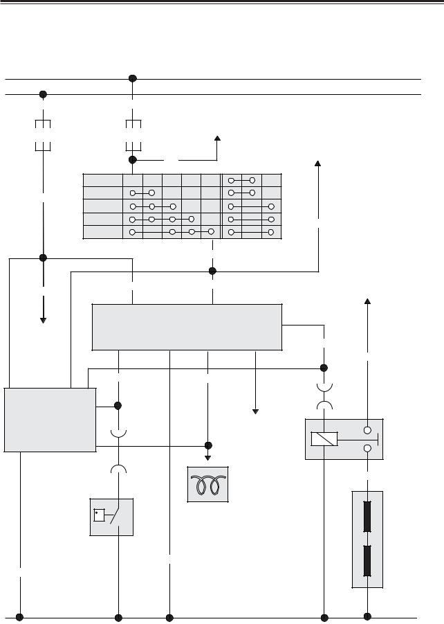
2.CIRCUIT DIAGRAM BY SYSTEMS
4.HEATING SYSTEM CIRCUIT DIAGRAM
|
|
|
|
|
|
|
|
|
30 |
|
|
|
|
|
|
|
|
|
15b |
|
W |
|
|
R |
|
|
|
|
|
|
F20 |
|
|
F1 |
1. Tachograph |
|
|
||
|
|
|
|
|
|
|
|
||
|
10A |
|
|
15A |
|
2. Instrument A-4 |
|
|
|
|
|
|
|
|
|
|
|
||
|
|
|
|
|
|
|
|
1. Transmission neautrol S/W |
|
|
|
|
|
|
WR |
|
|
2. DE12TIS ECM #40 |
|
|
|
|
|
1 |
|
|
|
|
|
|
|
|
|
|
|
|
|
|
|
|
|
LOCK |
B |
ACC ON |
R |
ST |
|
|
|
|
RB |
|
ACC |
|
|
|
|
|
|
|
|
ON |
|
|
|
|
|
|
|
|
|
|
|
|
|
|
|
|
|
|
|
|
P |
|
|
|
|
LO |
|
|
|
START |
|
|
|
|
|||
|
|
|
|
|
|
|
|||
|
|
|
|
|
|
|
4 |
|
|
|
|
|
|
|
|
|
LO |
|
|
|
RB |
|
|
RB |
|
|
LO |
|
Starter |
|
|
|
6 |
|
|
4 |
|
motor B+ |
|
|
|
|
|
|
|
|
|
||
|
|
|
|
B+ |
|
|
ST |
|
|
|
|
|
Engine preheater unit |
Preheater control unit |
|
|
|||
|
1. Seat belt |
|
|
|
DV ENGINE |
5 |
|
||
|
2. Key hole |
|
|
|
|
|
|
GrW |
|
|
lamp unit |
|
|
3 |
|
|
|
|
|
|
|
|
|
8 |
|
7 |
|
Cable |
|
|
|
|
|
|
|
|
|
|
|
1 |
3 |
4 |
OB |
|
|
GR |
C203 |
|
|
|
|
|
|
|
11 |
|
|||
|
|
|
|
|
|
|
|
|
|
|
|
|
|
|
|
|
|
C311 |
|
|
TIMER Q.O.S |
|
2 |
|
|
|
|
11 |
|
|
|
|
|
|
Alternator |
|
|||
|
|
|
C203 |
|
|
|
|||
|
(DE12~12TI) |
|
|
|
|
|
|||
|
|
|
|
|
"L" terminal |
Engine |
|||
|
|
|
|
12 |
|
|
|
|
|
|
|
|
|
|
|
|
|
|
preheater |
|
5 |
|
9 |
|
|
|
|
|
control relay |
|
|
C311 |
|
|
|
|
|
||
|
|
|
|
|
|
|
|
||
|
|
|
|
12 |
|
|
|
|
Cable |
|
|
|
|
|
|
|
|
|
|
|
|
|
|
|
|
Instrument |
|
|
|
|
Coolant |
|
C |
|
|
|
|
||
|
|
|
(preheater indicator |
|
|
||||
|
Temperature |
|
|
|
|
|
lamp) |
|
|
|
|
|
|
|
|
|
|
Engine |
|
|
|
|
|
|
|
|
|
|
|
|
|
|
|
|
|
|
|
|
pre-heater |
|
|
|
|
|
|
|
|
|
|
|
|
|
|
|
|
|
|
|
heater oil |
|
|
|
|
|
B |
|
|
|
|
|
B |
|
|
|
|
|
|
|
|
|
G102 |
|
|
|
G102 |
|
|
31 |
|
|
|
|
|
|
|
|
|
|
|
|
|
|
|
|
|
|
32 |
|
|
 Loading...