


pbh160_bu_1609929F02_t.fm Seite 1 Dienstag, 5. Oktober 2004 11:25 11
Bedienungsanleitung Operating instructions Instructions d’utilisation Instrucciones de servicio Manual de instruções Istruzioni d’uso Gebruiksaanwijzing Betjeningsvejledning Bruksanvisning Brukerveiledningen Käyttöohje
δηγία ειρισµ ύ
Kullan∂m k∂lavuzu
Deutsch
English
Français
Español
Português
Italiano
Nederlands
Dansk
Svenska
Norsk
Suomi
Eλληvικά
Türkçe
* Des idées en action.
PBH 160 RE PBH 180 RE PBH 1800 RE PBH 200 RE PBH 200 FRE
pbh160_bu_1609929F02_t.fm Seite 2 Dienstag, 5. Oktober 2004 11:25 11
A |
6 |
|
B |
|
|
|
|
|
16
C |
|
|
D |
|
|
|
|
5
a
b
3
E |
|
|
F |
|
|
|
|
3
18
17
19
pbh160_bu_1609929F02_t.fm Seite 3 Dienstag, 5. Oktober 2004 11:25 11
G |
|
|
H |
|
|
3 |
|
|
|
21
|
20 |
I |
K |
13
14
L |
|
|
M |
|
|
|
|
8
22 12
t 15

pbh160_bu_1609929F02_t.fm Seite 4 Dienstag, 5. Oktober 2004 11:25 11
N |
|
|
O |
|
|
|
|
9
P |
|
|
R |
|
|
|
|
|
|
S
pbh160_bu_1609929F02_t.fm Seite 5 Dienstag, 5. Oktober 2004 11:25 11
1
2 6
5
4
3
|
|
|
10 |
|
|
14 13 |
12 11 |
8 |
7 |
15 |
|
9 |
|
|
|
|
|
|
PBH 200 FRE
PBH 160 RE/
PBH 180 RE/
PBH 1800 RE/
PBH 200 RE
pbh160_bu_1609929F02_t.fm Seite 1 Dienstag, 5. Oktober 2004 11:25 11
Gerätekennwerte
Bohrhammer |
|
PBH 160 RE |
PBH 180 RE |
PBH 200 RE |
PBH 200 FRE |
|
|
|
PBH 1800 RE |
|
|
|
|
|
|
|
|
Sachnummer |
|
0 603 376 86. |
0 603 376 8.. |
0 603 376 7.. |
0 603 376 76. |
Wechselbohrfutter |
|
– |
– |
– |
● |
|
|
|
|
|
|
Drehzahlsteuerung |
|
● |
● |
● |
● |
Drehzahlvorwahl |
|
● |
● |
● |
● |
|
|
|
|
|
|
Rechts-/Linkslauf |
|
● |
● |
● |
● |
Nennaufnahmeleistung |
[W] |
500 |
510 |
530 |
550 |
|
|
|
|
|
|
Schlagzahl |
[min-1] |
0 ... 4800 |
0 ... 4800 |
0 ... 4800 |
0 ... 4800 |
Einzelschlagstärke |
[J] |
1,3 |
1,3 |
1,4 |
1,5 |
|
|
|
|
|
|
Nenndrehzahl |
[min-1] |
0 ... 1100 |
0 ... 1100 |
0 ... 1100 |
0 ... 1100 |
Werkzeugaufnahme SDS-plus |
|
● |
● |
● |
● |
|
|
|
|
|
|
Ø Spindelhals |
[mm] |
43 (Euro-Norm) |
43 (Euro-Norm) |
43 (Euro-Norm) |
43 (Euro-Norm) |
Bohrdurchmesser (max.): |
|
|
|
|
|
Beton |
[mm] |
16 |
18 |
20 |
20 |
Holz |
[mm] |
30 |
30 |
30 |
30 |
Stahl |
[mm] |
13 |
13 |
13 |
13 |
|
|
|
|
|
|
Gewicht entsprechend EPTA- |
|
|
|
|
|
Procedure 01/2003 |
[kg] |
2,0 |
2,0 |
2,0 |
2,1 |
Schutzklasse |
|
/ II |
/ II |
/ II |
/ II |
Angaben gelten für Nennspannungen [U] 230/240 V. Bei niedrigeren Spannungen und in länderspezifischen Ausführungen können diese Angaben variieren.
Bitte die Sachnummer auf dem Typenschild Ihres Gerätes beachten, die Handelsbezeichnungen einzelner Geräte können variieren.
Geräusch-/Vibrationsinformation
Messwerte ermittelt entsprechend EN 60745.
Der A-bewertete Geräuschpegel des Gerätes beträgt typischerweise:
Schalldruckpegel: 1 , Schallleistungspegel: 2 . Messunsicherheit K = 3 dB.
Gehörschutz tragen!
Die bewertete Beschleunigung beträgt typischerweise
3 . |
|
|
|
|
|
|
|
|
2 |
|
3 |
|
|
1 |
|
||
|
|
|
|
|
|
PBH 160 RE |
85 dB(A) |
96 dB(A) |
|
9 m/s2 |
|
PBH 180 |
RE |
85 dB(A) |
96 dB(A) |
|
9 m/s2 |
PBH 1800 RE |
85 dB(A) |
96 dB(A) |
|
9 m/s2 |
|
PBH 200 |
RE |
91 dB(A) |
102 dB(A) |
|
11 m/s2 |
PBH 200 |
FRE |
91 dB(A) |
102 dB(A) |
|
11 m/s2 |
Bestimmungsgemäßer Gebrauch
Das Gerät ist bestimmt zum Hammerbohren in Beton, Ziegel und Gestein. Es ist ebenso geeignet zum Bohren ohne Schlag in Holz, Metall, Keramik und Kunststoff.
Geräte mit elektronischer Regelung und Rechts-/ Linkslauf sind auch geeignet zum Schrauben und Gewindeschneiden.
1 609 929 F02 • (04.10) T |
Deutsch–1 |

pbh160_bu_1609929F02_t.fm Seite 2 Dienstag, 5. Oktober 2004 11:25 11
Geräteelemente
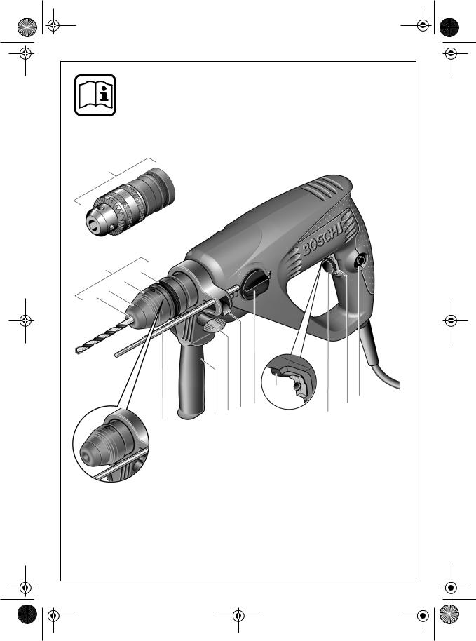
Bitte klappen Sie die Ausklappseite mit der Darstellung des Gerätes auf, und lassen Sie diese Seite aufgeklappt, während Sie die Bedienungsanleitung lesen.
Die Nummerierung der Geräteelemente bezieht sich auf die Darstellung des Gerätes auf der Grafikseite.
113-mm-Zahnkranz-Wechselbohrfutter
2SDS-plus-Wechselbohrfutter
3Werkzeugaufnahme (SDS-plus)
4Staubschutzkappe
5Verriegelungshülse
6Wechselbohrfutter-Verriegelungsring
7Feststellknopf
8Ein-Aus-Schalter
9Drehzahlregler
10Rechts-Linkslauf-Schalter
11Betriebsarten-Wahlschalter
12Taste Tiefenanschlag
13Flügelschraube Zusatzgriff
14Zusatzgriff
15Tiefenanschlag
16Bohrfutteraufnahme
17Bohrfutter*
18SDS-plus-Bohrfutterschaft*
19Bohrfutter montiert*
20SDS-plus-Adapter*
21Bohrfutterschlüssel*
22Skalenwert Tiefenanschlag
*Abgebildetes oder beschriebenes Zubehör gehört teilweise nicht zum Lieferumfang.
Zu Ihrer Sicherheit
Sämtliche Anweisungen sind zu lesen. Fehler bei der Einhaltung der nachstehend aufgeführten Anweisungen können elektrischen Schlag, Brand und/oder schwere Verletzungen verursachen.
BEWAHREN SIE DIESE ANWEI-
SUNGEN GUT AUF.
Zusätzlich müssen die allgemeinen Sicherheitshinweise im beigefügten Heft befolgt werden.
■Tragen Sie Gehörschutz. Die Einwirkung von Lärm kann Gehörverlust bewirken.
■Benutzen Sie das Gerät nicht mit beschädigtem Kabel. Berühren Sie das beschädigte Kabel nicht und ziehen Sie den Netzstecker, wenn das Kabel während des Arbeitens beschädigt wird. Beschädigte Kabel erhöhen das Risiko eines elektrischen Schlages.
■Schließen Sie Geräte, die im Freien verwendet werden, über einen Fehlerstrom(FI)-Schutz- schalter an.
■Verwenden Sie geeignete Suchgeräte, um verborgene Versorgungsleitungen aufzuspüren, oder ziehen Sie die örtliche Versorgungsgesellschaft hinzu. Kontakt mit Elektroleitungen kann zu Feuer und elektrischem Schlag führen. Beschädigung einer Gasleitung kann zur Explosion führen. Eindringen in eine Wasserleitung verursacht Sachbeschädigung oder kann einen elektrischen Schlag verursachen.
■Benutzen Sie die mit dem Elektrowerkzeug mitgelieferten Zusatzgriffe. Der Verlust der Kontrolle über die Maschine kann zu Verletzungen führen.
■Sichern Sie das Werkstück. Ein mit Spannvorrichtungen oder Schraubstock festgehaltenes Werkstück ist sicherer gehalten als mit Ihrer Hand.
■Bearbeiten Sie kein asbesthaltiges Material.
Asbest gilt als krebserregend.
■Halten Sie das Gerät beim Arbeiten fest mit beiden Händen und sorgen Sie für einen sicheren Stand. Das Gerät wird mit zwei Händen sicherer geführt.
■Warten Sie, bis das Gerät zum Stillstand gekommen ist, bevor Sie es ablegen. Das Einsatzwerkzeug kann sich verhaken und zum Verlust der Kontrolle über das Gerät führen.
1 609 929 F02 • (04.10) T |
Deutsch–2 |
pbh160_bu_1609929F02_t.fm Seite 3 Dienstag, 5. Oktober 2004 11:25 11
Bohrfutter wechseln (PBH 200 FRE)
Das SDS-plus-Wechselbohrfutter kann leicht am Bohrhammer gegen das mitgelieferte ZahnkranzWechselbohrfutter ausgetauscht werden.
Hammerbohren ist nur mit SDS-plus-Werkzeugen möglich, die in das SDS-plus-Wechselbohrfutter eingesetzt werden.
Bohren und Schrauben sind auch mit Werkzeugen ohne SDS-plus (z.B. Rundschaftbohrer, Schrauberbits) möglich, die in das Zahnkranz-Wechselbohrfutter eingespannt werden.
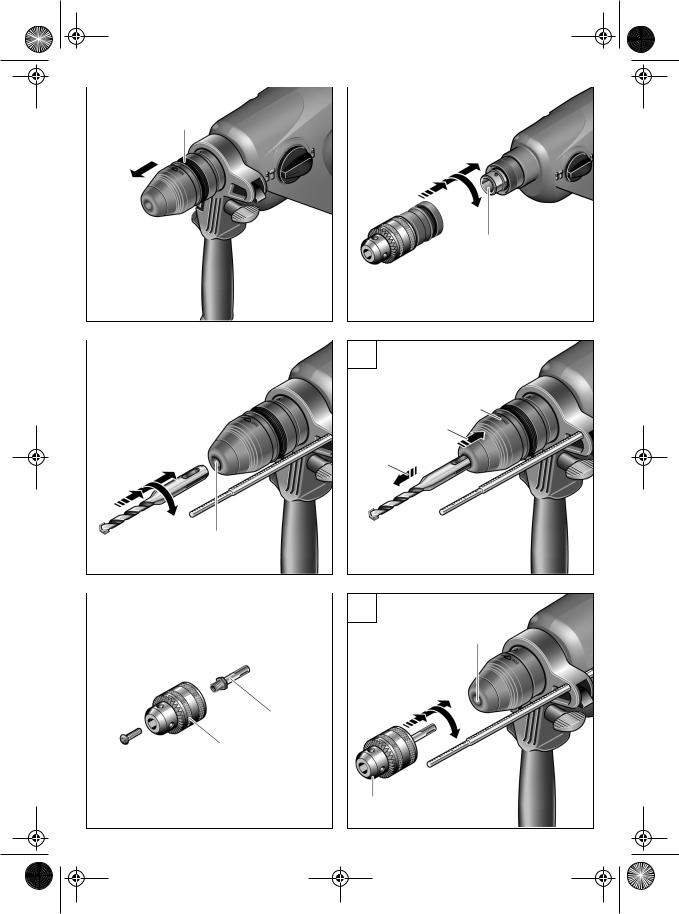
Wechselbohrfutter abnehmen (Bild A )
■Verletzungsgefahr! Vor dem Abnehmen des Wechselbohrfutters unbedingt Werkzeuge oder Bits entfernen.
Verriegelungsring 6 des SDS-plus-Wechselbohrfutters umgreifen und kräftig in Pfeilrichtung ziehen. Das Wechselbohrfutter löst sich.
Wechselbohrfutter aufsetzen (Bild B )
Zahnkranz-Wechselbohrfutter mit der ganzen Hand umgreifen. Drehend auf die Bohrfutteraufnahme aufsetzen, bis das Einrasten deutlich zu hören ist. Das Wechselbohrfutter verriegelt selbsttätig.
Verriegelung durch Ziehen am Wechselbohrfutter prüfen.
Den umgekehrten Austausch entsprechend vornehmen.
Wartung des Wechselbohrfutters
Die Verbindungsteile staubfrei halten. Schmierung ist nicht notwendig.
Werkzeug wechseln (Bild C–I)
Beim Wechseln der Werkzeuge darauf achten, dass die Staubschutzkappe 4 nicht beschädigt wird.
SDS-plus-Werkzeuge
Das SDS-plus-Werkzeug ist systembedingt frei beweglich. Dadurch entsteht beim Leerlauf eine Rundlaufabweichung, die sich beim Bohren selbsttätig zentriert. Dies hat keine Auswirkungen auf die Genauigkeit des Bohrlochs.
Einsetzen (Bild C )
Werkzeug vor dem Einsetzen reinigen und leicht fetten.
Das staubfreie Werkzeug in die Werkzeugaufnahme 3 drehend bis zum Einrasten einschieben.
Das Werkzeug verriegelt sich selbsttätig. Verriegelung durch Ziehen am Werkzeug prüfen.
Entnehmen (Bild D )
Verriegelungshülse 5 nach hinten ziehen (a), halten, und das Werkzeug entnehmen (b).
Werkzeuge ohne SDS-plus
Werkzeuge ohne SDS-plus nicht zum Hammerbohren oder Meißeln verwenden!
PBH 160 RE/180 RE/1800 RE/200 RE
Um mit Werkzeugen ohne SDS-plus (z.B. Bohrer mit zylindrischem Schaft) arbeiten zu können, muss ein Bohrfutter 17 mit SDS-plus-Bohrfutterschaft 18 (Zubehör) in die Werkzeugaufnahme eingesetzt werden (Bild E ).
Das staubfrei zusammengebaute Bohrfutter in die Werkzeugaufnahme 3 drehend bis zum Einrasten einschieben (Bild F ).
Das Werkzeug verriegelt sich selbsttätig. Verriegelung durch Ziehen am Werkzeug prüfen.
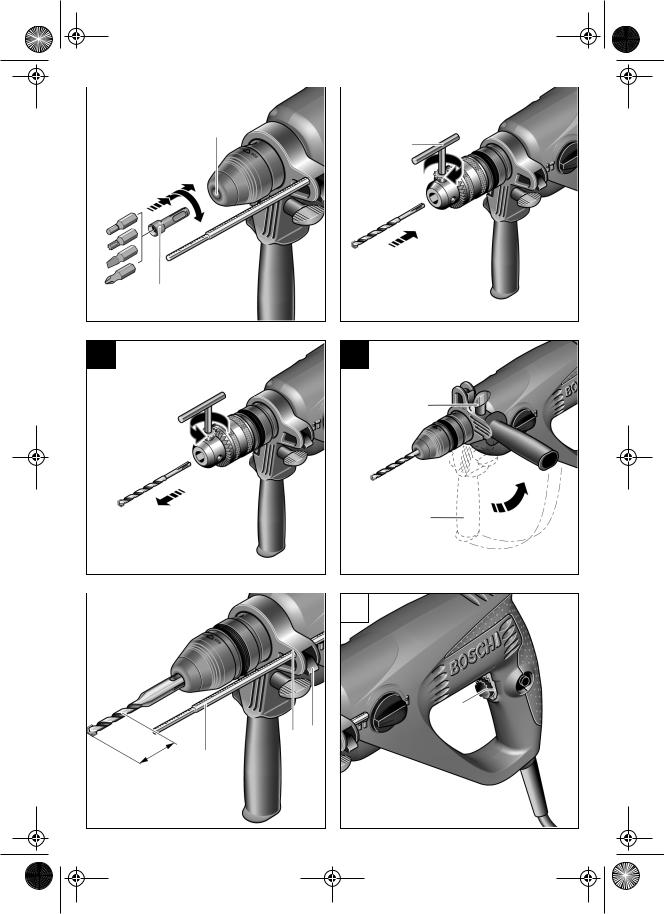
Schrauberbits (Bild G )
Für Schrauberbits SDS-plus-Adapter 20 (Zubehör) verwenden.
PBH 200 FRE
Werkzeug einsetzen (Bild H )
Hülse des Zahnkranz-Wechselbohrfutters drehen, bis die Werkzeugaufnahme weit genug geöffnet ist. Werkzeug einsetzen und mit Bohrfutterschlüssel 21 gleichmäßig in allen drei Bohrungen spannen.
Für Schrauberbits handelsüblichen Bithalter einsetzen. Schrauberbits in Bithalter stecken. Nur zum Schraubenkopf passende Schrauberbits verwenden. Schrauberbits können auch ohne Bithalter eingesetzt werden.
Werkzeug entnehmen (Bild I )
Zum Entnehmen eines Werkzeuges aus dem Zahn- kranz-Wechselbohrfutter Hülse in Pfeilrichtung drehen, bis das Werkzeug entnommen werden kann.
System-Zubehör
Zugehörige Einsatzwerkzeuge siehe Bosch-Katalog. Eine Zubehörauflistung finden Sie am Ende dieser Anleitung.
Inbetriebnahme
Netzspannung beachten!
Die Spannung der Stromquelle muss mit den Angaben auf dem Typenschild des Gerätes übereinstimmen. Mit 230 V gekennzeichnete Geräte können auch an 220 V betrieben werden.
Ein-Aus-Schalten
Zur Inbetriebnahme des Gerätes den Ein-Aus- Schalter 8 drücken.
Zum Feststellen den Ein-Aus-Schalter 8 in gedrücktem Zustand mit dem Feststellknopf 7 arretieren.
Zum Ausschalten des Gerätes den Ein-Aus-Schalter 8 loslassen bzw. drücken und loslassen.
1 609 929 F02 • (04.10) T |
Deutsch–3 |
pbh160_bu_1609929F02_t.fm Seite 4 Dienstag, 5. Oktober 2004 11:25 11
Arbeitshinweise (Bild K–N)
■Setzen Sie das Elektrowerkzeug nur ausgeschaltet auf die Mutter/Schraube auf.
Zusatzgriff (Bild K )
■Das Gerät darf aus Sicherheitsgründen nur mit dem Zusatzgriff 14 verwendet werden.
Durch Schwenken des Zusatzgriffes 14 wird eine ermüdungsfreiere und dadurch sichere Körperhaltung erreicht.
Flügelschraube 13 am Zusatzgriff 14 lockern. Griff schwenken. Flügelschraube wieder festziehen.
Überlastkupplung
Klemmt oder hakt das Einsatzwerkzeug, wird der Antrieb zur Bohrspindel unterbrochen. Halten Sie, wegen der dabei auftretenden Kräfte, das Elektrowerkzeug immer mit beiden Händen gut fest und nehmen Sie einen festen Stand ein.
Tiefenanschlag (Bild  )
)
Mit dem Tiefenanschlag 15 kann die Bohrtiefe t eingestellt werden. Taste 12 drücken und Tiefenanschlag bis zur Höhe der Bohrerspitze herausziehen. Skalenwert 22 ablesen, gewünschte Bohrtiefe t davon abziehen und berechneten Skalenwert einstellen.
Staubabsaugung/Saugfix
■Treffen Sie Schutzmaßnahmen, wenn beim Arbeiten gesundheitsschädliche, brennbare oder explosive Stäube entstehen können. Zum Beispiel: Manche Stäube gelten als krebserregend. Verwenden Sie eine Staub-/Späneabsaugung und tragen Sie eine Staubschutzmaske.
■Halten Sie Ihren Arbeitsplatz sauber. Materialmischungen sind besonders gefährlich. Leichtmetallstaub kann brennen oder explodieren.
Das Gerät kann direkt an der Steckdose eines Bosch Allzwecksaugers mit Fernstarteinrichtung angeschlossen werden. Dieser wird beim Einschalten des Gerätes automatisch gestartet.
Saugfix (Zubehör) montieren und Staubsauger anschließen.
Bis zur vorbestimmten Bohrtiefe federt der Saugfix zurück. Dadurch wird der Saugfix-Kopf immer dicht an der Oberfläche gehalten.
Drehzahl einstellen (Bild  )
)
Durch zuoder abnehmenden Druck auf den Ein-Aus- Schalter 8 kann die Drehzahl während des Betriebs stufenlos gesteuert werden.
Vorteile:
–langsames Anbohren, z.B. auf glatten Flächen wie Fliesen,
–kein Abrutschen des Bohrers beim Anbohren,
–kein Aussplittern des Bohrlochs.
Drehzahl vorwählen (Bild  )
)
Mit dem Drehzahlregler 9 kann die gewünschte Höchstdrehzahl vorgewählt werden.
Durch die Begrenzung kann der Ein-Aus-Schalter nur noch bis zur eingestellten Höchstdrehzahl durchgezogen werden.
Die Drehzahl muss je nach Betriebsart, zu bearbeitendem Material und entsprechend dem Bohrdurchmesser ausgewählt werden.
Richtwerte dazu siehe Betriebsarten.
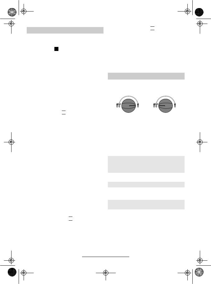
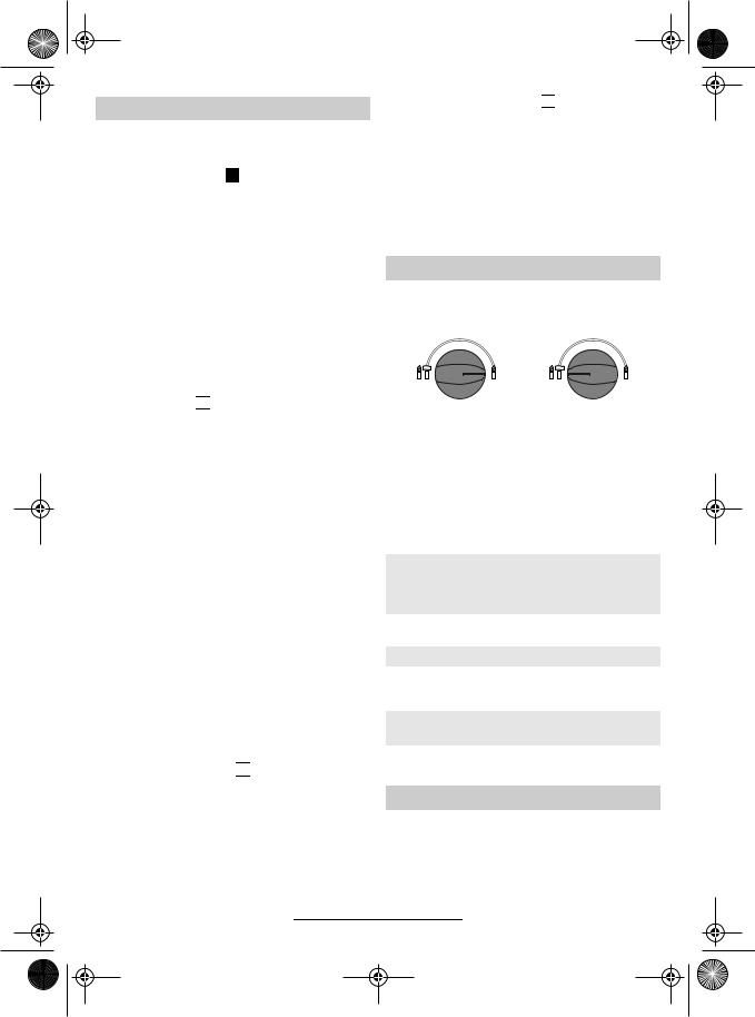
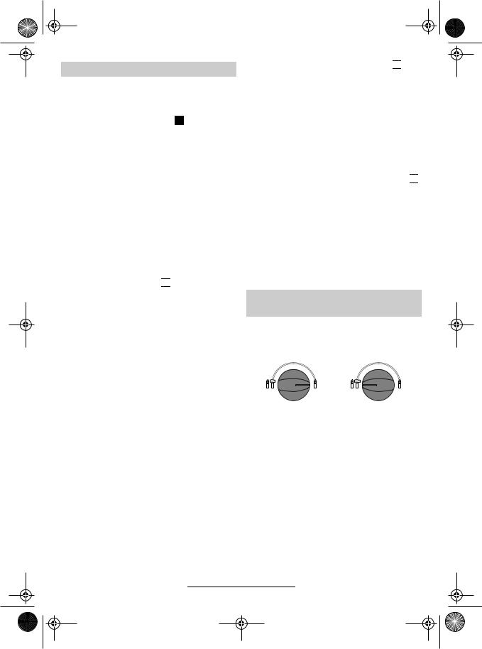
Betriebsarten (Bild O–S)
Am Betriebsarten-Wahlschalter 11 wird der Getriebezustand für den jeweiligen Anwendungsfall eingestellt:
Bohren Hammerbohren
Der Betriebsarten-Wahlschalter darf nur im Stillstand betätigt werden.
Werkzeuge ohne SDS-plus nicht zum Hammerbohren oder Meißeln verwenden!
Die folgende Tabelle zeigt, wie der BetriebsartenWahlschalter 11, der Rechts-Linkslauf-Schalter 10 sowie der Drehzahlregler 9 für die verschiedenen Betriebsarten einzustellen sind (Bilder siehe Klappseite):
Betriebsart |
Typ PBH |
160 RE/
180 RE/
200 FRE
1800 RE/
200 RE
Hammerbohren
in Beton oder Stein
Bohren in Stahl oder Holz
Schrauben
Rechtslauf
Linkslauf
Meißeln
nur mit MV 200 (Zubehör)
Bild |
O |
Bild |
O |
Bild |
|
Bild |
|
P |
P |
||
Bild |
|
Bild |
|
R |
R |
||
Bild |
S |
Bild |
S |
Bild |
|
– |
|
O |
|
1 609 929 F02 • (04.10) T |
Deutsch–4 |

pbh160_bu_1609929F02_t.fm Seite 5 Dienstag, 5. Oktober 2004 11:25 11
Wartung und Reinigung
■Vor allen Arbeiten am Gerät Netzstecker ziehen.
■Halten Sie das Gerät und die Lüftungsschlitze des Gerätes stets sauber, um gut und sicher zu arbeiten.
Werkzeugaufnahme täglich säubern.
Staubschutzkappe auswechseln
Beschädigte Staubschutzkappe rechtzeitig auswechseln, da Staub, der in die Werkzeugaufnahme eindringt, zu Funktionsstörungen führt.
Es wird empfohlen, dies von einem Kundendienst vornehmen zu lassen.
Sollte das Gerät trotz sorgfältiger Herstellund Prüfverfahren einmal ausfallen, ist die Reparatur von einer autorisierten Kundendienststelle für Bosch-Elektro- werkzeuge ausführen zu lassen.
Bei allen Rückfragen und Ersatzteilbestellungen bitte unbedingt die 10-stellige Sachnummer laut Typenschild des Gerätes angeben.
Service und Kundenberater
Explosionszeichnungen und Informationen zu Ersatzteilen finden Sie unter: www.bosch-pt.com.
www.powertool-portal.de, das Internetportal für Heimwerker und Gartenfreunde
www.dha.de, das komplette Service-Angebot der Deutschen Heimwerker Akademie
Deutschland
Robert Bosch GmbH
Servicezentrum Elektrowerkzeuge
Zur Luhne 2
37589 Kalefeld
Service:. . . . . . . . . . . . . . . . . . . 01 80/3 35 54 99
Fax . . . . . . . . . . . . . . . . . . . + 49 (0) 55 53/20 22 37
Kundenberater: . . . . . . . . . . . . . 01 80/3 33 57 99
Österreich
ABE Service GmbH Jochen-Rindt-Straße 1 1232 Wien
Service:. . . . . . . . . . . . . . . . . . +43 (0)1/61 03 80 Fax . . . . . . . . . . . . . . . . . . . . . +43 (0)1/61 03 84 91Kundenberater: . . . . . . . . +43 (0)1/7 97 22 30 66 E-Mail: abe@abe-service.co.at
Schweiz
Service:. . . . . . . . . . . . . . . . . +41 (0)1/847 16 16
Fax . . . . . . . . . . . . . . . . . . . . . . +41 (0)1/847 16 57
Kundenberater . . . . . . . . . . . . . . 0 800 55 11 55
Umweltschutz |
|
Konformitätserklärung |
|
|
|
Rohstoffrückgewinnung statt Müllentsorgung
Gerät, Zubehör und Verpackung sollten einer umweltgerechten Wiederverwertung zugeführt werden.
Diese Anleitung ist aus chlorfrei gefertigtem RecyclingPapier hergestellt.
Zum sortenreinen Recycling sind Kunststoffteile gekennzeichnet.
In Deutschland können nicht mehr gebrauchsfähige Geräte zum Recycling beim Handel abgegeben oder (ausreichend frankiert) direkt eingeschickt werden an:
Recyclingzentrum Elektrowerkzeuge
Osteroder Landstr. 3
37589 Kalefeld
Wir erklären in alleiniger Verantwortung, dass dieses Produkt mit den folgenden Normen oder normativen Dokumenten übereinstimmt:
EN 60745 gemäß den Bestimmungen der Richtlinien 89/336/EWG, 98/37/EG.
Dr. Egbert Schneider |
Dr. Eckerhard Strötgen |
Senior Vice President |
Head of Product |
Engineering |
Certification |
|
|
|
|
Robert Bosch GmbH, Geschäftsbereich Elektrowerkzeuge
Änderungen vorbehalten
1 609 929 F02 • (04.10) T |
Deutsch–5 |
pbh160_bu_1609929F02_t.fm Seite 1 Dienstag, 5. Oktober 2004 11:25 11
Product Specifications
Rotary Hammer |
|
PBH 160 RE |
PBH 180 RE |
PBH 200 RE |
PBH 200 FRE |
|
|
|
PBH 1800 RE |
|
|
|
|
|
|
|
|
Article number |
|
0 603 376 86. |
0 603 376 8.. |
0 603 376 7.. |
0 603 376 76. |
Exchangeable drill chuck |
|
– |
– |
– |
● |
|
|
|
|
|
|
Speed control |
|
● |
● |
● |
● |
Speed preselection |
|
● |
● |
● |
● |
|
|
|
|
|
|
Right/Left rotation |
|
● |
● |
● |
● |
Rated input power |
[W] |
500 |
510 |
530 |
550 |
|
|
|
|
|
|
Impact rate |
[per min] |
0 ... 4800 |
0 ... 4800 |
0 ... 4800 |
0 ... 4800 |
Impact energy per stroke |
[J] |
1.3 |
1.3 |
1.4 |
1.5 |
|
|
|
|
|
|
Nominal speed |
[RPM] |
0 ... 1100 |
0 ... 1100 |
0 ... 1100 |
0 ... 1100 |
Tool holder SDS-plus |
|
● |
● |
● |
● |
|
|
|
|
|
|
Spindle collar diameter |
[mm] |
43 |
43 |
43 |
43 |
|
|
(Euro-Standard) |
(Euro-Standard) |
(Euro-Standard) |
(Euro-Standard) |
Maximum drill diameter: |
|
|
|
|
|
Concrete |
[mm] |
16 |
18 |
20 |
20 |
Wood |
[mm] |
30 |
30 |
30 |
30 |
Steel |
[mm] |
13 |
13 |
13 |
13 |
|
|
|
|
|
|
Weight in accordance with |
|
|
|
|
|
EPTA-Procedure 01/2003 |
[kg] |
2.0 |
2.0 |
2.0 |
2.1 |
Protection class |
|
/ II |
/ II |
/ II |
/ II |
The specifications apply for the rated voltage of [U] 230/240 V. For lower voltages and with models for specific countries, the specifications can vary.
Please refer to the article number on the nameplate of your machine since the trade designation of individual machines can vary.
Noise/Vibration Information
Measured values determined according to EN 60745.
Typically, the A-weighted noise levels of the tool are: Sound pressure level: 1 , Sound power level: 2 . Measuring inaccuracy K = 3 dB.
Wear ear protection!
The typical weighted acceleration is 3 .
|
|
1 |
2 |
3 |
PBH 160 |
RE |
85 dB(A) |
96 dB(A) |
9 m/s2 |
PBH 180 |
RE |
85 dB(A) |
96 dB(A) |
9 m/s2 |
PBH 1800 RE |
85 dB(A) |
96 dB(A) |
9 m/s2 |
|
PBH 200 |
RE |
91 dB(A) |
102 dB(A) |
11 m/s2 |
PBH 200 |
FRE |
91 dB(A) |
102 dB(A) |
11 m/s2 |
Intended Use
The machine is intended for hammer drilling in concrete, brick and stone. It is also suitable for drilling without impact in wood, metal, ceramic and plastic.
Machines with electronic control and right/left rotation are also suitable for screw driving and thread cutting.
1 609 929 F02 • (04.10) T |
English–1 |
pbh160_bu_1609929F02_t.fm Seite 2 Dienstag, 5. Oktober 2004 11:25 11
Product Elements
Please open the foldout page with the illustration of the tool and leave it open while you read these operating instructions.
The numbering of the machine elements refers to the illustration of the machine on the graphic page.
1Ring gear exchangeable drill chuck, 13 mm
2SDS-plus exchangeable drill chuck
3Tool holder (SDS-plus)
4Dust protection cap
5Locking sleeve
6Exchangeable drill chuck locking ring
7Locking button
8On/off switch
9Speed control
10Right/left rotation switch
11Operational mode selection switch
12Depth stop button
13Auxiliary handle wing screw
14Auxiliary handle
15Depth stop
16Drill chuck holder
17Drill chuck*
18SDS-plus drill chuck shaft*
19Assembled drill chuck*
20SDS-plus adapter*
21Drill chuck key*
22Depth stop scale value
*Not all the accessories illustrated or described are included in standard delivery.
For Your Safety
Read all instructions. Failure to follow all instructions listed below may result in electric shock, fire and/or serious injury.
SAVE THESE INSTRUCTIONS.
In addition, the general safety notes in the enclosed booklet must be observed.
■Wear hearing protection. The noise can cause loss of hearing.
■Do not use the machine with a damaged cable. If the cable is damaged while working, do not touch the damaged cable but pull the mains plug. A damaged cable increases the risk of an electrical shock.
■For machines used outdoors, connect to the mains using a fault current (FI) protection switch.
■Use suitable detectors to find hidden utility lines or call the local utility company for assistance. Contact with electric lines can lead to fire or electrical shock. Damaging a gas line can result in an explosion. Penetrating a water pipe will cause property damage or an electrical shock.
■Always use the auxiliary handle provided with the machine. The loss of control over the machine can result in injuries.
■Secure the work piece. A work piece clamped with clamping devices or in a vice is held more securely than by hand.
■Do not work with materials containing asbestos. Asbestos is considered carcinogenic.
■Hold the machine firmly with both hands while working and provide for secure footing. The machine is more securely guided with both hands.
■Wait until the machine has come to a standstill before placing it down. The insertion tool can become caught and lead to loss of control over the machine.
1 609 929 F02 • (04.10) T |
English–2 |
pbh160_bu_1609929F02_t.fm Seite 3 Dienstag, 5. Oktober 2004 11:25 11
Changing the Drill Chuck
(PBH 200 FRE)
The SDS-plus exchangeable drill chuck can easily be replaced on the rotary hammer with the ring gear exchangeable drill chuck provided.
Hammer drilling is possible only with SDS-plus tools that are inserted in the SDS-plus exchangeable drill chuck.
Drilling and screwdriving are also possible with tools without SDS-plus (e.g., round shaft drills, screwdriver bits) that are clamped in the ring gear exchangeable drill chuck.
Removing the Exchangeable Drill Chuck
(Fig. A )
■Danger of injury! Before removing the exchangeable drill chuck, always remove the tool or bit.
Grasp the locking ring 6 of the SDS-plus exchangeable drill chuck and pull forcefully in the direction of the arrow. The exchangeable drill chuck comes off.
Attaching the Exchangeable Drill Chuck
(Fig. B )
Take hold of the ring gear exchangeable drill chuck with the whole hand. Place it with a twisting motion on the chuck holder until it can clearly be heard to latch. The exchangeable drill chuck locks itself.
Check locking by pulling on the exchangeable drill chuck.
Make exchanges in the reverse order in a corresponding manner.
Maintenance of the Exchangeable Drill Chucks
Keep the connecting parts free of dust. Lubrication is not necessary.
Tools without SDS-plus
Do not use tools without SDS-plus for hammer drilling or chiselling!
PBH 160 RE/180 RE/1800 RE/200 RE
To work with tools without SDS-plus (e.g., drills with cylindrical shafts), a drill chuck 17 with a SDS-plus chuck shaft 18 (optional accessory) must be inserted into the tool holder (Fig. E ).
Insert the dust-free, assembled chuck into the tool holder 3 with twisting until it latches (Fig. F ).
The chuck locks itself. Check the locking by pulling on the chuck.
Srewdriver Bits (Fig. G )
For screwdriver bits, use the SDS-plus adapter 20 (optional accessory).
PBH 200 FRE
Tool Insertion (Fig. H )
Turn the collar of the ring gear exchangeable drill chuck until the tool holder is opened wide enough. Insert the tool and clamp with the drill chuck key 21 uniformly in all three holes.
For screwdriver bits, insert a commercially available bit holder. Insert the screwdriver bits into the bit holder. Use only screwdriver bits that fit the screw heads. Screwdriver bits may also be inserted without a bit holder.
Tool Removal (Fig. I )
To remove a tool from the ring gear exchangeable drill chuck, turn the collar in the direction of the arrow until the tool can be removed.
System Accessories
Refer to the Bosch Catalogue for insertion tools.
A list of accessories can be found at the end of these instructions.
Tool Changing (Fig. C–I)
Take care that the dust protection cap 4 is not damaged when changing tools.
SDS-plus Tools
The SDS-plus tool is designed to be freely movable. This causes eccentricity when the machine is off-load. However, the drill automatically centres itself during operation. This does not affect drilling precision.
Inserting (Fig. C )
Clean and lightly oil the tool before inserting.
Insert the dust-free tool into the tool holder 3 with twisting until it latches.
The tool locks itself. Check the locking by pulling on the tool.
Removing (Fig. D )
Pull the locking sleeve 5 to the rear (a) and hold while removing the tool (b).
Putting into Operation
Ensure that the mains voltage is correct!
The voltage of the power source must agree with the value given on the nameplate of the machine. Machines designated for 230 V can also be operated with 220 V.
Switching On/Off
To switch on the machine, press the on/off switch 8.
Lock the depressed on/off switch 8 by pressing the lock-on button 7.
To switch off the machine, release the on/off switch 8 or press and then release it.
1 609 929 F02 • (04.10) T |
English–3 |
pbh160_bu_1609929F02_t.fm Seite 4 Dienstag, 5. Oktober 2004 11:25 11
Working Instructions (Fig. K–N)
■Place the machine on the nut/screw only when it is switched off.
Auxiliary Handle (Fig. K )
■For safety reasons, the machine should be used only with the auxiliary handle 14.
By rotating the auxiliary handle 14 to a comfortable position, a fatigue-free and therefore safe working position can be achieved.
Loosen the winged screw 13 on the auxiliary handle 14. Swing the grip to a new position. Retighten the winged screw.
Overload Clutch
If the insertion tool becomes caught or jammed, the drive to the drill spindle is interrupted. As a result of the forces that occur, always hold the machine firmly with both hands and provide for a sure footing.
Depth Stop (Fig.  )
)
With the depth stop 15, the drilling depth t can be set. Press the button 12 and pull out the depth stop to the tip of the drill. Read the value from the scale 22, subtract the desired drilling depth t and set the resulting value on the depth stop scale.
Dust Vacuuming/Vacuuming Attachment
■Take protective measures when dust is produced while working that is detrimental to health, combustible or explosive. For example: Some dusts are considered to be carcinogenic. Use dust/chip extraction and wear a protective mask.
■Keep your workplace clean. Material mixtures are especially dangerous. Light metal dust can burn or explode.
The machine can be connected directly to the socket of a Bosch all-purpose vacuum cleaner with remote starting. The vacuum cleaner starts automatically when the machine is switched on.
Mount the vacuuming attachment (optional accessory) and connect the vacuum cleaner.
The vacuuming attachment is spring loaded up to the preselected drilling depth. In this manner, the vacuuming attachment head is always held close to the surface.
Setting the Speed (Fig.  )
)
By increasing or decreasing the pressure on the on/off switch 8, the speed can be continuously controlled during operation.
Advantages:
–Slow starting of holes, e.g., on smooth surfaces or tiles
–No sliding off of the drill when starting the hole
–No splintering of the hole.
Speed Pre-Selection (Fig.  )
)
With the speed regulator 9, the required highest speed can be pre-set.
As a result of this limitation, the on/off switch can be pressed only to the pre-set highest speed.
The speed must be selected according to the operating mode, the material to be worked and the diameter of the drill.
See Operating Modes for recommended values.
Operating Modes (Fig. O–S)
The operation of the gearbox for each application is set with the mode selection switch 11:
Drilling |
Hammer Drilling |
The operating mode selector switch may be actuated only at a standstill.
Do not use tools without SDS-plus for hammer drilling or chiselling!
The following table shows how the operating mode selector switch 11, the right/left rotation switch 10 as well as the speed regulator 9 are to be set for the various operating modes (See fold-out page for figures):
Operating Mode |
Type PBH |
160 RE/
180 RE/
200 FRE
1800 RE/
200 RE
Hammer drilling in concrete or stone
Drilling in steel or wood
Screw driving
Right rotation
Left rotation
Chiselling only with MV 200 (optional accessory)
Fig. |
O |
Fig. |
O |
Fig. |
|
Fig. |
|
P |
P |
||
Fig. |
|
Fig. |
|
R |
R |
||
Fig. |
S |
Fig. |
S |
Fig. |
|
– |
|
O |
|||
Maintenance and Cleaning
■Before any work on the machine itself, pull the mains plug.
■Always keep the machine and the ventilation slots clean for proper and safe working.
Clean the tool holder daily.
1 609 929 F02 • (04.10) T |
English–4 |
pbh160_bu_1609929F02_t.fm Seite 5 Dienstag, 5. Oktober 2004 11:25 11
Replacing the Dust Protection Cap
Damaged dust protection caps should be replaced as soon as possible since dust that enters the tool holder can cause malfunctions.
It is recommended that this be performed by customer service.
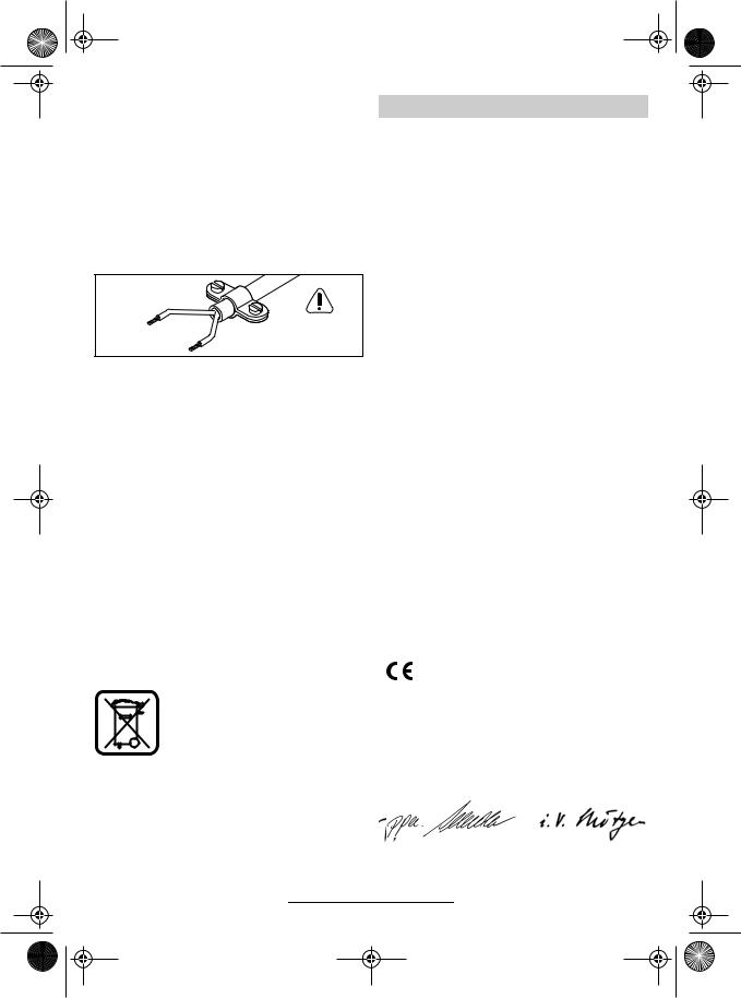
WARNING
Important instructions for connecting a new 3- pin plug to the 2-wire cable.
The wires in the cable are coloured according to the following code:
Strain relief
Live = brown
|
To be fitted |
|
by qualified |
Neutral = blue |
professionals only |
|
Do not connect the blue or brown wire to the earth terminal of the plug.
Important: If the plug on the cable of this machine must be replaced, dispose of the old plug to prevent misuse.
If the machine should fail despite the care taken in manufacture and testing, repair should be carried out by an authorised customer services agent for Bosch power-tools.
For all inquiries and replacement parts ordering, always include the 10-place article number on the nameplate of the machine.
Service and Customer Advice
Exploded views and information on spare parts can be found under: www.bosch-pt.com.
Great Britain
Robert Bosch Ltd. (B.S.C.) P.O. Box 98
Broadwater Park
North Orbital Road
Denham-Uxbridge Middlesex UB 9 5HJ
Service . . . . . . . . . . . . . . +44 (0) 18 95/83 87 82Advice line. . . . . . . . . . . . +44 (0) 18 95/83 87 91 Fax . . . . . . . . . . . . . . . . . . . +44 (0) 18 95/83 87 89
Ireland
Beaver Distribution Ltd.
Greenhills Road
Tallaght-Dublin 24
Service . . . . . . . . . . . . . . . . + 353 (0)1/414 9400
Fax . . . . . . . . . . . . . . . . . . . . . + 353 (0)1/459 8030
Australia
Robert Bosch Australia L.t.d. RBAU/SBT2
1555 Centre Road
P.O. Box 66 Clayton
3168 Clayton/Victoria
. . . . . . . . . . . . . . . . . . . . . +61 (0)1/800 804 777 Fax . . . . . . . . . . . . . . . . . . . . +61 (0)1/800 819 520 www.bosch.com.au
E-Mail: CustomerSupportSPT@au.bosch.com
New Zealand
Robert Bosch Limited 14-16 Constellation Drive Mairangi Bay
Auckland New Zealand
. . . . . . . . . . . . . . . . . . . . . . . +64 (0)9/47 86 158 Fax . . . . . . . . . . . . . . . . . . . . . . +64 (0)9/47 82 914
Environmental Protection |
|
Declaration of Conformity |
|
|
|
Recycle raw materials instead of disposing as waste.
The machine, accessories and packaging should be submitted for environment-friendly recycling.
These instructions are printed on recycled paper manufactured without chlorine.
The plastic components are labelled for categorised recycling.
We declare under our sole responsibility that this product is in conformity with the following standards or standardization documents:
EN 60745 according to the provisions of the directives 89/336/EEC, 98/37/EC.
Dr. Egbert Schneider |
Dr. Eckerhard Strötgen |
Senior Vice President |
Head of Product |
Engineering |
Certification |
|
|
|
|
Robert Bosch GmbH, Geschäftsbereich Elektrowerkzeuge
Specifications subject to change without notice
1 609 929 F02 • (04.10) T |
English–5 |
pbh160_bu_1609929F02_t.fm Seite 1 Dienstag, 5. Oktober 2004 11:25 11
Caractéristiques techniques
Marteau perforateur |
|
PBH 160 RE |
PBH 180 RE |
PBH 200 RE |
PBH 200 FRE |
|
|
|
PBH 1800 RE |
|
|
|
|
|
|
|
|
N° d’article |
|
0 603 376 86. |
0 603 376 8.. |
0 603 376 7.. |
0 603 376 76. |
Mandrin interchangeable |
|
– |
– |
– |
● |
|
|
|
|
|
|
Régulation de la vitesse |
|
● |
● |
● |
● |
Sélection de la vitesse |
|
● |
● |
● |
● |
|
|
|
|
|
|
Inversion du sens de rotation |
|
● |
● |
● |
● |
Puissance absorbée |
[W] |
500 |
510 |
530 |
550 |
|
|
|
|
|
|
Fréquence de frappe |
[min-1] |
0 ... 4800 |
0 ... 4800 |
0 ... 4800 |
0 ... 4800 |
Travail par coup |
[J] |
1,3 |
1,3 |
1,4 |
1,5 |
|
|
|
|
|
|
Vitesse nominale |
[min-1] |
0 ... 1100 |
0 ... 1100 |
0 ... 1100 |
0 ... 1100 |
Porte-outil SDS-plus |
|
● |
● |
● |
● |
|
|
|
|
|
|
Ø Collet de broche |
[mm] |
43 (Euro-Norm) |
43 (Euro-Norm) |
43 (Euro-Norm) |
43 (Euro-Norm) |
Diamètre (max.) : |
|
|
|
|
|
Béton |
[mm] |
16 |
18 |
20 |
20 |
Bois |
[mm] |
30 |
30 |
30 |
30 |
Acier |
[mm] |
13 |
13 |
13 |
13 |
|
|
|
|
|
|
Poids suivant |
|
|
|
|
|
EPTA-Procedure 01/2003 |
[kg] |
2,0 |
2,0 |
2,0 |
2,1 |
Classe de protection |
|
/ II |
/ II |
/ II |
/ II |
Ces indications sont valables pour des tensions nominales de [U] 230/240 V. Ces indications peuvent varier pour des tensions plus basses ainsi que pour des versions spécifiques à certains pays.
Faire attention au numéro d’article se trouvant sur la plaque signalétique de l’appareil. Les désignations commerciales des différents appareils peuvent varier.
Bruits et vibrations
Valeurs de mesures obtenues conformément à la norme européenne 60745.
Les mesures réelles (A) des niveaux acoustiques de l’appareil sont :
Niveau de pression acoustique : 1 , Niveau de puissance acoustique : 2 . Incertitude de mesure K = 3 dB.
Se munir d’une protection acoustique !
L’accélération réelle mesurée est 3 .
|
|
1 |
2 |
3 |
PBH 160 |
RE |
85 dB(A) |
96 dB(A) |
9 m/s2 |
PBH 180 |
RE |
85 dB(A) |
96 dB(A) |
9 m/s2 |
PBH 1800 RE |
85 dB(A) |
96 dB(A) |
9 m/s2 |
|
PBH 200 |
RE |
91 dB(A) |
102 dB(A) |
11 m/s2 |
PBH 200 |
FRE |
91 dB(A) |
102 dB(A) |
11 m/s2 |
Utilisation conforme
L’appareil est conçu pour les travaux de perçage en frappe dans le béton, la brique ou la pierre. Il est également approprié pour le perçage sans frappe dans le bois, le métal, la céramique et les matières plastiques. Les appareils avec réglage électronique et rotation à droite/à gauche sont également appropriés pour le vissage et le filetage.
1 609 929 F02 • (04.10) T |
Français–1 |

pbh160_bu_1609929F02_t.fm Seite 2 Dienstag, 5. Oktober 2004 11:25 11
Eléments de l’appareil
Dépliez le volet sur lequel l’appareil est représenté de manière graphique. Laissez le volet déplié pendant la lecture de la présente notice d’utilisation.
La numérotation des éléments de l’appareil se rapporte aux figures représentant l’appareil sur la page des graphiques.
1Mandrin 13 mm à clé
2Mandrin interchangeable SDS-plus
3Porte-outil (SDS-plus)
4Capuchon anti-poussières
5Douille de verrouillage
6Bague de verrouillage du mandrin interchangeable
7Bouton de marche permanente
8Interrupteur Marche/Arrêt
9Molette de réglage de la vitesse
10Commutateur de sens de rotation droite/gauche
11Sélecteur de mode de fonctionnement
12Touche pour butée de profondeur
13Vis à ailettes de la poignée supplémentaire
14Poignée supplémentaire
15Butée de profondeur
16Fixation du mandrin de perçage
17Mandrin*
18Queue pour mandrin SDS-plus*
19Mandrin monté*
20Adaptateur SDS-plus*
21Clé de mandrin*
22Valeur sur la graduation de la butée de profondeur
*Les accessoires reproduits ou décrits ne sont pas tous compris dans le contenu de l’emballage.
■Porter une protection acoustique. Une forte exposition au bruit peut provoquer une perte d’audition.
■Ne jamais utiliser un appareil dont le câble est endommagé. Ne pas toucher à un câble endommagé et retirer la fiche du câble d’alimentation de la prise du courant, au cas où le câble serait endommagé lors du travail. Un câble endommagé augmente le risque d’un choc électrique.
■Brancher les appareils qui sont utilisés à l’extérieur sur un disjoncteur différentiel.
■Utiliser des détecteurs appropriés afin de localiser la présence de conduites électriques ou bien s’adresser à la société locale de distribution. Un contact avec des lignes électriques peut provoquer un incendie et une décharge électrique. Le fait d’endommager une conduite de gaz peut entraîner une explosion. Le fait d’endommager une conduite d’eau peut entraîner des dégâts matériels ou causer une décharge électrique.
■Utiliser les poignées supplémentaires fournies avec l’outil électroportatif. Le fait de perdre le contrôle de l’appareil peut entraîner de blessures.
■Bloquer la pièce à travailler. Une pièce à travailler serrée par des dispositifs de serrage ou dans un étau est fixée de manière plus sûre que lorsqu’elle est immobilisée à la main.
■Ne pas travailler de matériaux contenant de l’amiante. L’amiante est considérée comme étant cancérigène.
■Toujours bien tenir l’appareil des deux mains et veiller à toujours garder une position de travail stable. Avec les deux mains, l’appareil est guidé de manière plus sûre.
■Avant de déposer l’appareil, attendre que ce- lui-ci soit complètement à l’arrêt. L’outil de travail risque de se coincer, ce qui entraîne une perte de contrôle de l’appareil.
Pour votre sécurité
Lire toutes les indications. Le non-respect des instructions indiquées ci-après peut entraîner un choc électrique, un incendie et/ou de graves blessures sur les personnes.
GARDER PRECIEUSEMENT CES INSTRUCTIONS DE SECURITE.
Respecter en plus les indications générales de sécurité se trouvant dans le cahier ci-joint.
Remplacement du mandrin (PBH 200 FRE)
Le mandrin SDS-plus monté sur le perforateur peut très aisément être remplacé par le mandrin à clé fourni. Le percage en frappe n’est possible qu’avec des outils SDS-plus qui sont montés dans le mandrin SDS-plus. Percer et visser est également possible avec les outils sans SDS-plus (foret à tige cylindrique, embouts de tournevis, par exemple) qui sont montés dans le mandrin SDS-plus.
1 609 929 F02 • (04.10) T |
Français–2 |
pbh160_bu_1609929F02_t.fm Seite 3 Dienstag, 5. Oktober 2004 11:25 11
Démontage du mandrin interchangeable |
faut mettre en place sur le porte-outil un mandrin 17 |
|||||||||
(Fig. |
|
) |
avec une queue de mandrin SDS-plus pour mandrin |
|||||||
A |
||||||||||
|
18 (accessoire) (Fig. |
|
). |
|
|
|||||
■ Risques de blessures corporelles. Avant de dé- |
E |
|||||||||
monter le mandrin interchangeable, toujours au préa- |
En lui imprimant un léger mouvement de rotation sur |
|||||||||
lable retirer l’embout de vissage ou l’outil en place. |
son axe, engager le mandrin monté sur la queue de |
|||||||||
Saisir la bague de verrouillage 6 du mandrin interchan- |
fixation SDS-plus (l’ensemble étant exempt de pous- |
|||||||||
geable SDS-plus. Avec énergie, la faire tourner dans le |
sières) dans la fixation d’outil 3, jusqu’à ce qu’il enclen- |
|||||||||
sens de la flèche. Le mandrin interchangeable se dé- |
che (Fig. |
F |
). |
|
|
|||||
bloque. |
Le verrouillage de l’outil s’effectue de manière auto- |
|||||||||
|
|
|
matique. Contrôler qu’il est bien verrouillé en position |
|||||||
Mise en place du mandrin interchangeable |
de travail en tirant dessus. |
|||||||||
(Fig. |
|
) |
|
|
|
|
|
|
|
|
B |
Embouts de vissage (Fig. |
|
) |
|||||||
G |
||||||||||
|
|
|
||||||||
Saisir le mandrin à clé à pleine main. Le mettre en place au niveau de la fixation du mandrin du marteau-per- forateur en lui imprimant un mouvement de rotation, jusqu’à entendre distinctement le bruit caractéristique indiquant qu’il est enclenché. Le mandrin interchangeable se verrouille automatiquement.
Contrôler le verrouillage en tirant sur le mandrin automatique.
Procéder à l’échange inverse de la même manière.
Maintenance du mandrin interchangeable
Les pièces de liaison doivent rester exemptes de poussières. Aucun graissage n’est nécessaire.
Changement d’outil (Fig. C–I)
En changeant d’outil, prendre garde à ne pas endommager le capuchon anti-poussières 4.
Outils SDS-plus
Une fois correctement mis en place, un outil SDS-plus peut encore librement bouger. Ceci est une caractéristique du système SDS-plus. Il en résulte un fauxrond en marche à vide qui se corrige de lui-même lors du perçage et n’affecte en rien la précision du travail.
Mise en place (Fig. C )
Avant de mettre un outil en place, le nettoyer et le graisser légèrement.
En lui imprimant un léger mouvement de rotation sur son axe, engager l’outil exempt de poussière dans le porte-outil 3, jusqu’à ce qu’il enclenche.
Le verrouillage de l’outil s’effectue de manière automatique. Contrôler qu’il est bien verrouillé en position de travail en tirant dessus.
Enlèvement de l’outil (Fig. D )
Tirer la douille de verrouillage 5 vers l’arrière (a), la maintenir dans cette position et retirer l’outil (b).
Pour utiliser des embouts de tournevis, avoir recours à l’adaptateur SDS-plus 20 (accessoire).
PBH 200 FRE
Mise en place de l’outil (Fig. H )
Faire tourner la bague du mandrin à clé jusqu’à ce que le mandrin soit suffisamment ouvert pour recevoir la tige de l’outil. Mettre l’outil en place puis refermer et bloquer de manière homogène les trois mâchoires du mandrin avec la clé 21 appropriée (cf. les trois alésages du mandrin).
Pour les embouts de vissage, utiliser les porte-em- bouts du commerce. Introduire l’embout de vissage dans le porte-embouts. N’utiliser que des embouts adaptés aux têtes de vis mises en oeuvre. Les embouts de tournevis peuvent aussi être mis sans porteembouts.
Démontage de l’outil (Fig. I )
Pour démonter un outil mis en place dans le mandrin à clé, faire tourner la bague du mandrin dans la direction de la flèche jusqu’à pouvoir extraire l’outil.
Accessoires compatibles
Pour plus de détails sur les outils utilisables avec cet appareil : cf. le catalogue Bosch.
Une liste des accessoires figure à la fin du présent manuel d’instructions.
Mise en service
Tenir compte de la tension du secteur !
La tension de la source de courant doit correspondre aux indications figurant sur la plaque signalétique de l’appareil. Les appareils fonctionnant sous 230 V peuvent également être utilisés sous 220 V.
Mise en fonctionnement/Arrêt
Outils sans SDS-plus
Ne jamais utiliser d’outils sans SDS-plus pour le perçage en frappe ou le burinage !
PBH 160 RE/180 RE/1800 RE/200 RE
Pour travailler avec des outils sans système de fixation SDS-plus (forets à queue cylindrique, par exemple), il
Afin de mettre l’appareil en fonctionnement, appuyer sur l’interrupteur Marche/Arrêt 8.
Afin de bloquer l’interrupteur Marche/Arrêt 8 en position « Marche », appuyer sur le bouton de verrouillage 7.
Afin d’arrêter l’appareil, relâcher l’interrupteur Marche/Arrêt 8 ou appuyer sur l’interrupteur et le relâcher.
1 609 929 F02 • (04.10) T |
Français–3 |
pbh160_bu_1609929F02_t.fm Seite 4 Dienstag, 5. Oktober 2004 11:25 11
Conseils pratiques (Fig. K–N)
■Poser l’outil électroportatif sur la vis/sur l’écrou seulement lorsque l’appareil est en position « Arrêt ».
Poignée supplémentaire (Fig. K )
■Pour des raisons de sécurité, l’appareil ne doit être mis en oeuvre qu’avec la poignée supplémentaire 14.
Le pivotement de la poignée supplémentaire 14 favorise le cas échéant une position de travail moins fatiguante pour le corps, donc plus sûre.
Débloquer la vis à ailettes 13 au niveau de la poignée supplémentaire 14. Faire pivoter la poignée. Rebloquer les vis à ailettes.
Dispositif anti-surcharge à crabot
Dès que l’outil de travail se coince ou qu’il s’accroche, l’entraînement de la broche de perçage est interrompu. En raison des forces pouvant en résulter, toujours bien tenir l’outil électroportatif des deux mains et veiller à garder une position stable et équilibrée.
Butée de profondeur (Fig.  )
)
La butée de profondeur 15 sert à régler et contrôler la profondeur de perçage t. Appuyer sur la touche 12 et sortir la butée de profondeur jusqu’à ce qu’elle arrive à la hauteur de l’extrémité du foret. Lire la valeur correspondante sur la graduation 22. Retirer de cette valeur la profondeur de perçage t souhaitée et régler la butée de profondeur sur la valeur ainsi obtenue.
Aspiration de poussières/Set d’aspiration
■Prendre des mesures de sécurité, lorsque des poussières nuisibles à la santé, inflammables ou explosives peuvent être générées lors du travail. Par exemple : Certaines poussières sont considérées comme étant cancérigènes. Utiliser un dispositif d’aspiration de poussières/de copeaux et porter un masque anti-poussières.
■Tenir propre la place de travail. Les mélanges de matériaux sont particulièrement dangereux. Les poussières de métaux légers peuvent être explosives ou inflammables.
L’appareil peut être raccordé directement à la prise électrique d’un aspirateur universel Bosch équipé d’un dispositif de démarrage à distance. Ce dispositif lance automatiquement l’aspirateur à chaque fois que l’appareil qui lui est raccordé est mis en marche.
Monter le set d’aspiration avec tuyau souple (accessoire) sur l’appareil et raccorder l’aspirateur.
Montée sur ressort, la tête du set d’aspiration recule progressivement avec l’avance de l’outil dans la paroi, jusqu’à la profondeur de perçage préalablement définie. Elle reste ainsi toujours au plus près de la surface.
Réglage de la vitesse de rotation (Fig.  )
)
Le fait d’exercer une pression plus ou moins forte sur l’interrupteur Marche/Arrêt 8 permet d’ajuster en continu pendant le travail la vitesse de rotation de l’outil.
Avantages :
–Amorces de perçage plus lentes et donc mieux contrôlées (sur surfaces lisses : carrelages, par exemple).
–Pas de dérapage du foret lors des amorces de trous.
–Pas de fissuration ou d’éclatement du trous de perçage.
Présélection de la vitesse de rotation (Fig.  )
)
La molette 9 permet de présélectionner la vitesse de rotation maximale désirée pour l’opération considérée. Avec la limitation, l’interrupteur Marche/Arrêt ne peut être enfoncé que pour atteindre la vitesse de rotation maximale que vous avez déterminée.
La vitesse de rotation doit être choisie en fonction du mode de fonctionnement sélectionné, du matériau travaillé et du diamètre de l’outil.
Pour quelques valeurs indicatives, cf. chapitre Mode de fonctionnement.
Modes de fonctionnement (Fig. O–S)
Le sélecteur de mode de fonctionnement 11 permet de sélectionner la configuration de l’entraînement convenant le mieux à l’application couramment envisagée :
Perçage |
Percage en frappe |
Le sélecteur de mode de fonctionnement ne doit être activé que lorsque l’outillage est hors marche.
Pour le perçage en frappe ou le burinage, ne jamais utiliser d’outils sans SDS-plus !
1 609 929 F02 • (04.10) T |
Français–4 |
pbh160_bu_1609929F02_t.fm Seite 5 Dienstag, 5. Oktober 2004 11:25 11
Le tableau suivant montre comment configurer le sélecteur de mode de fonctionnement 11, le commutateur de sens de rotation droite/gauche 10 ainsi que la molette de réglage de la vitesse 9 en fonction des différents modes de fonctionnement (figures : cf. volet rabattu) :
Mode de fonctionnement |
|
Modèle PBH |
||||
|
160 RE/ |
|
|
|
||
|
180 RE/ |
200 FRE |
||||
|
1800 RE/ |
|||||
|
|
|
|
|||
|
200 RE |
|
|
|
||
Percage en frappe |
Fig. |
|
|
Fig. |
|
|
O |
|
O |
|
|||
du béton et de la pierre |
|
|
||||
|
|
|
|
|
|
|
|
|
|
|
|
|
|
Perçage dans l’acier |
Fig. |
|
|
Fig. |
|
|
P |
|
P |
|
|||
ou le bois |
|
|
||||
|
|
|
|
|
|
|
Vissage |
|
|
|
|
|
|
Rotation vers la droite |
Fig. |
R |
|
Fig. |
R |
|
Rotation vers la gauche |
Fig. |
S |
|
Fig. |
S |
|
|
|
|
|
|
|
|
Burinage : seulement avec |
Fig. |
|
|
– |
||
O |
|
|||||
MV 200 (accessoire) |
|
|||||
|
|
|
|
|
|
|
|
|
|
|
|
|
|
Maintenance et nettoyage
■Avant toute intervention sur l’appareil, toujours retirer la fiche du câble d’alimentation de la prise électrique.
■Toujours tenir propres l’appareil ainsi que les ouies de ventilation afin d’obtenir un travail impeccable et sûr.
Nettoyer quotidiennement le porte-outil.
Remplacement du capuchon anti-poussières
Un capuchon anti-poussières endommagé doit être remplacé à temps afin que la poussière ne puisse pénétrer dans le porte-outil et ainsi menacer le bon fonctionnement de l’appareil.
Il est recommandé de confier cette intervention à un centre de service agréé.
Si, malgré tous les soins apportés à la fabrication et au contrôle de l’appareil, celui-ci devait avoir un défaut, la réparation ne doit être confiée qu’à une station de service après-vente pour outillage Bosch agréée.
Pour toute demande de renseignements ou commande de pièces de rechange, nous préciser impérativement le numéro de série à dix chiffres se trouvant sur la plaque signalétique de l’appareil.
Instructions de protection de l’environnement
Récupération des matières premières plutôt qu’élimination des déchets
L’appareil comme d’ailleurs ses accessoires et emballages, doivent pouvoir suivre chacun une voie de recyclage appropriée.
Ce manuel d’instructions a été fabriqué à partir d’un papier recyclé blanchi en l’absence de chlore.
De même, nos pièces plastiques ont été marquées en vue d’un recyclage sélectif des différents matériaux.
Service Après-Vente
Vous trouverez des vues éclatées ainsi que des informations concernant les pièces de rechange sous : www.bosch-pt.com.
France
Robert Bosch France S.A.S. Service Après-vente/Outillage 126, Rue de Stalingrad 93700 Drancy
Centre d’appels SAV. . . . . . . . . . . 0143 11 90 06 N° vert Conseiller Bosch . . . . . . . . 0800 05 50 51
Belgique
. . . . . . . . . . . . . . . . . . . . . . . +32 (0)2/525 51 43 Fax . . . . . . . . . . . . . . . . . . . . . . +32 (0)2/525 54 20 E-mail: Outillage.Gereedschappen@be.bosch.com
Suisse
. . . . . . . . . . . . . . . . . . . . . . . +41 (0)1/847 16 16 Fax . . . . . . . . . . . . . . . . . . . . . . +41 (0)1/847 16 57
Service conseil client . . . . . . . . . . 0 800 55 11 55
Déclaration de conformité
Nous déclarons sous notre propre responsabilité que ce produit est en conformité avec les normes ou documents normalisés : EN 60745 conformément aux termes des réglementations 89/336/CEE, 98/37/CE.
Dr. Egbert Schneider |
Dr. Eckerhard Strötgen |
Senior Vice President |
Head of Product |
Engineering |
Certification |
|
|
|
|
Robert Bosch GmbH, Geschäftsbereich Elektrowerkzeuge
Sous réserve de modifications
1 609 929 F02 • (04.10) T |
Français–5 |
pbh160_bu_1609929F02_t.fm Seite 1 Dienstag, 5. Oktober 2004 11:25 11
Características técnicas
Martillo perforador |
|
PBH 160 RE |
PBH 180 RE |
PBH 200 RE |
PBH 200 FRE |
|
|
|
PBH 1800 RE |
|
|
|
|
|
|
|
|
Nº de art. |
|
0 603 376 86. |
0 603 376 8.. |
0 603 376 7.. |
0 603 376 76. |
Portabrocas intercambiable |
|
– |
– |
– |
● |
|
|
|
|
|
|
Control de revoluciones |
|
● |
● |
● |
● |
Preselección de revoluciones |
|
● |
● |
● |
● |
|
|
|
|
|
|
Giro derecha/izq. |
|
● |
● |
● |
● |
Potencia absorbida nominal |
[W] |
500 |
510 |
530 |
550 |
|
|
|
|
|
|
Número de percusiones |
[min-1] |
0 ... 4800 |
0 ... 4800 |
0 ... 4800 |
0 ... 4800 |
Energía por percusión |
[J] |
1,3 |
1,3 |
1,4 |
1,5 |
|
|
|
|
|
|
Revoluciones nominales |
[min-1] |
0 ... 1100 |
0 ... 1100 |
0 ... 1100 |
0 ... 1100 |
Portaútiles SDS-plus |
|
● |
● |
● |
● |
|
|
|
|
|
|
Ø Cuello del husillo |
[mm] |
43 |
43 |
43 |
43 |
|
|
(Norma Euro) |
(Norma Euro) |
(Norma Euro) |
(Norma Euro) |
Diámetro de taladro máx. en: |
|
|
|
|
|
Hormigón |
[mm] |
16 |
18 |
20 |
20 |
Madera |
[mm] |
30 |
30 |
30 |
30 |
Acero |
[mm] |
13 |
13 |
13 |
13 |
|
|
|
|
|
|
Peso determinado según |
|
|
|
|
|
EPTA-Procedure 01/2003 |
[kg] |
2,0 |
2,0 |
2,0 |
2,1 |
Clase de protección |
|
/ II |
/ II |
/ II |
/ II |
Estos datos son válidos para tensiones nominales de [U] 230/240 V. Los valores pueden variar si la tensión fuese inferior, y en las ejecuciones específicas para ciertos países.
Observe por favor el nº de art. en la placa de características de su herramienta eléctrica. Las denominaciones comerciales en ciertas herramientas eléctricas pueden variar.
Información sobre ruido y vibraciones
Determinación de los valores de medición según norma EN 60745.
El nivel de ruido típico del aparato determinado con un filtro A corresponde a:
Nivel de presión de sonido: 1 , Nivel de potencia acústica: 2 . Inseguridad de la medición K = 3 dB.
¡Usar protectores auditivos!
La aceleración se eleva normalmente a |
3 . |
||||
|
|
|
2 |
|
3 |
|
|
1 |
|
||
|
|
|
|
|
|
PBH 160 |
RE |
85 dB(A) |
96 dB(A) |
|
9 m/s2 |
PBH 180 |
RE |
85 dB(A) |
96 dB(A) |
|
9 m/s2 |
PBH 1800 RE |
85 dB(A) |
96 dB(A) |
|
9 m/s2 |
|
PBH 200 |
RE |
91 dB(A) |
102 dB(A) |
|
11 m/s2 |
PBH 200 |
FRE |
91 dB(A) |
102 dB(A) |
|
11 m/s2 |
Utilización reglamentaria
El aparato ha sido proyectado para taladrar con percusión en hormigón, ladrillo y piedra. Además es adecuado también para taladrar sin percutir en madera, metal, cerámica y materiales sintéticos.
Los aparatos regulados electrónicamente, con inversión del sentido de giro, son adecuados además para atornillar y para tallar roscas.
1 609 929 F02 • (04.10) T |
Español–1 |
pbh160_bu_1609929F02_t.fm Seite 2 Dienstag, 5. Oktober 2004 11:25 11
Elementos del aparato
Despliegue la solapa con la representación del aparato y manténgala abierta mientras lee estas instrucciones de manejo.
La numeración de los elementos del aparato está referida a su imagen en la página ilustrada.
1Portabrocas intercambiable de corona dentada de 13 mm
2Portabrocas intercambiable SDS-plus
3Portaútiles (SDS-plus)
4Caperuza antipolvo
5Casquillo de enclavamiento
6Anillo de enclavamiento de portabrocas intercambiable
7Botón de enclavamiento
8Interruptor de conexión/desconexión
9Regulador de revoluciones
10Conmutador de inversión de giro
11Selector del modo de operación
12Tecla para el tope de profundidad
13Tornillo de mariposa para la empuñadura adicional
14Empuñadura adicional
15Tope de profundidad
16Alojamiento del portabrocas
17Portabrocas*
18Vástago de portabrocas SDS-plus*
19Portabrocas montado*
20Adaptador SDS-plus*
21Llave del portabrocas*
22Valor en la escala del tope de profundidad
*Los accesorios ilustrados o descritos pueden no corresponder al material suministrado de serie con el aparato.
■Colóquese unos protectores auditivos. El ruido producido puede provocarle sordera.
■No utilice el aparato si el cable estuviese dañado. No toque el cable dañado, y saque el enchufe de la red si el cable se daña durante el trabajo. Los cables deteriorados comportan un mayor riesgo de electrocución.
■Los aparatos utilizados en la intemperie deberán conectarse a través de un fusible diferencial (FI).
■Utilice unos aparatos de exploración adecuados para detectar posibles conductores o tuberías ocultas, o consulte a sus compañías abastecedoras locales. El contacto con conductores eléctricos puede provocar una descarga eléctrica e incluso un incendio. Al dañar una tubería de gas puede producirse una explosión. La perforación de una tubería de agua pueden causar daños materiales o una descarga eléctrica.
■Utilice la herramienta eléctrica con las empuñaduras suministradas. La pérdida del control sobre la máquina puede causar un accidente.
■Asegure la pieza de trabajo. Una pieza de trabajo fijada con unos dispositivos de sujeción, o en un tornillo de banco, se mantiene sujeta de forma mucho más segura que con la mano.
■No trabaje materiales que contengan amianto. El amianto es cancerígeno.
■Trabaje sujetando el aparato firmemente con ambas manos y manteniendo una postura estable. Un aparato sujeto con las dos manos es guiado con mayor seguridad.
■Antes de depositarlo, espere a que el aparato se haya detenido del todo. El útil podría engancharse y hacerle perder el control sobre el aparato.
Para su seguridad
Lea íntegramente estas instrucciones. En caso de no atenerse a las instrucciones de seguridad siguientes, ello puede dar lugar a una descarga eléctrica, incendio o lesión seria.
GUARDAR ESTAS INSTRUCCIONES EN UN LUGAR SEGURO.
Adicionalmente deberán respetarse las instrucciones de seguridad generales comprendidas en el folleto adjunto.
Cambio del portabrocas (PBH 200 FRE)
El portabrocas intercambiable SDS-plus del martillo perforador puede sustituirse sencillamente por el portabrocas de corona dentada intercambiable que se adjunta con el aparato.
Para taladrar con percusión es necesario emplear útiles SDS-plus junto con el portabrocas intercambiable SDS-plus.
También es posible taladrar y atornillar con útiles sin SDS-plus (p.ej. con brocas de vástago cilíndrico o láminas de destornillador) sujetándolos en el portabrocas intercambiable de corona dentada.
1 609 929 F02 • (04.10) T |
Español–2 |
pbh160_bu_1609929F02_t.fm Seite 3 Dienstag, 5. Oktober 2004 11:25 11
Desmontaje del portabrocas intercambiable (fig. A )
■¡Riesgo de lesión! Antes de desmontar el portabrocas intercambiable es indispensable retirar de él los útiles o láminas de destornillador!
Abrazar el anillo de enclavamiento 6 del portabrocas intercambiable SDS-plus y tirar fuertemente en dirección de la flecha. El portabrocas intercambiable se afloja.
Montaje del portabrocas intercambiable (fig. B )
Abrazar completamente con la mano el portabrocas intercambiable de corona dentada. Montarlo girando sobre el alojamiento del portabrocas hasta percibir claramente que ha quedado enclavado. El portabrocas intercambiable se enclava automáticamente.
Comprobar si ha quedado bien enclavado, tirando del portabrocas intercambiable.
Restituir el portabrocas procediendo de la manera correspondiente.
Mantenimiento del portabrocas intercambiable
Mantener las piezas de conexión libres de polvo. No es necesaria su lubricación.
Cambio del útil (fig. C–I)
Al cambiar de útil, cuidar de no dañar la caperuza antipolvo 4.
Utiles SDS-plus
Condicionado por el sistema, el útil SDS-plus se mueve libremente. Por ello, al funcionar en vacío, el útil puede girar con cierta excentricidad, la cual se elimina al taladrar, gracias a su efecto autocentrante. Esto no afecta en absoluto a la exactitud de la perforación.
Inserción (fig. C )
Limpiar y engrasar ligeramente el útil antes de su inserción.
Introducir girando el útil libre de polvo en el portaútiles 3 y empujarlo hasta que engatille.
El útil queda enclavado automáticamente. Comprobar su correcta sujeción tirando del útil.
Extracción (fig. D )
Desplazar el casquillo de enclavamiento 5 hacia atrás
(a), mantenerlo en esa posición y extraer el útil (b).
Utiles sin SDS-plus
¡No emplear útiles sin SDS-plus para taladrar con percusión o cincelar!
PBH 160 RE/180 RE/1800 RE/200 RE
Para poder trabajar con útiles sin SDS-plus (p.ej. brocas de vástago cilíndrico) debe montarse en el portaútiles un portabrocas 17 junto con un adaptador SDSplus para portabrocas 18 (accesorio) (fig. E ).
Insertar el portabrocas completado y libre de polvo girándolo en el portaútiles 3 y empujarlo hasta quedar enclavado (fig. F ).
El útil se bloquea por sí mismo. Verificar su enclavamiento tirando del útil.
Láminas de destornillador (fig. G )
Para montar láminas de destornillador se requiere el adaptador SDS-plus 20 (accesorio especial).
PBH 200 FRE
Inserción del útil (fig. H )
Girar el casquillo del portabrocas intercambiable de corona dentada hasta que el portaútiles esté suficientemente abierto. Insertar el útil y aplicar la llave de portabrocas 21 en cada uno de los tres taladros e irlo apretando uniformemente.
Para las láminas de destornillador emplear un sujetador de láminas usual en el comercio. Insertar las láminas en el sujetador de láminas de destornillador. Emplear únicamente las láminas de destornillador adecuadas a la cabeza del tornillo. Las láminas de destornillador pueden insertarse también sin utilizar un sujetador de láminas.
Extracción del útil (fig. I )
Para extraer un útil del portabrocas intercambiable de corona dentada, girar el casquillo en dirección de la flecha lo suficiente hasta poder extraer el útil.
Sistema de accesorios
Los útiles adaptables correspondientes se detallan en el catálogo Bosch.
Una lista de accesorios la encuentra al final de estas instrucciones.
Puesta en funcionamiento
¡Cerciorarse de que la tensión de la red sea correcta!
La tensión de la fuente de energía debe coincidir con las indicaciones en la placa de características del aparato. Los aparatos marcados con 230 V pueden funcionar también a 220 V.
Conexión y desconexión
Para la puesta en marcha del aparato presionar el interruptor de conexión/desconexión 8.
Para enclavar el interruptor de conexión/desconexión 8 mantenerlo apretado, y presionar el botón de enclavamiento 7.
Para desconectar el aparato soltar, o presionar y soltar si estuviese enclavado, el interruptor de conexión/ desconexión 8.
1 609 929 F02 • (04.10) T |
Español–3 |
 Loading...