


Dinion IP - NWC-0455
|
|
|
|
|
|
|
|
|
|
|
EN |
|
Installation Manual |
|
|
|
|
|
||
|
|
|
|
|
||
|
|
|
|
|
||
|
|
|
|
|
||
|
|
|
|
|
||
|
|
|
|
|
IP Camera |

Dinion IP | Installation Manual |
ii |
Copyright
This user guide is the intellectual property of Bosch Security Systems and is protected by copyright. All rights reserved. No part of this document may be reproduced or transmitted for any purpose, by whatever means, electronic or mechanical, without the express written permission of Bosch Security Systems.
Release: July 2005 (Software version 1.0)
© Copyright 2005 Bosch Security Systems
Note
This user guide has been compiled with great care and the information it contains has been thoroughly verified. The text was complete and correct at the time of printing. The ongoing development of the products may mean that the content of the user guide can change without notice. Bosch Security Systems accepts no liability for damage resulting directly or indirectly from faults, incompleteness or discrepancies between the user guide and the product described.
Trademarks
All hardware and software product names used in this document are likely to be registered trademarks and must be treated accordingly.
Bosch Security Systems | 2005-07

Dinion IP | Installation Manual |
EN | iii |
Contents
|
Important Safeguards ............................................................................................ |
vii |
|
FCC Information ............................................................................................. |
viii |
1. |
INTRODUCTION ................................................................................. |
11 |
|
Type number overview ......................................................................................... |
12 |
|
Unpacking ............................................................................................................... |
12 |
|
System requirements ............................................................................................ |
12 |
|
Overview of functions ........................................................................................... |
13 |
|
Wide dynamic range ...................................................................................... |
13 |
|
Power-over-Ethernet ...................................................................................... |
13 |
|
Receiver ............................................................................................................ |
13 |
|
Video encoding ............................................................................................... |
14 |
|
Dual Streaming ............................................................................................... |
14 |
|
Multicast ........................................................................................................... |
14 |
|
Configuration ................................................................................................... |
14 |
|
Snapshots ........................................................................................................ |
14 |
|
Backup .............................................................................................................. |
14 |
2. |
CONNECTIONS .................................................................................. |
15 |
|
Power ....................................................................................................................... |
15 |
|
Network (and power) ............................................................................................ |
15 |
|
Video service monitor ........................................................................................... |
16 |
|
Alarm connector .................................................................................................... |
16 |
|
Lens mounting ........................................................................................................ |
16 |
|
Mounting the camera ............................................................................................ |
17 |
3. |
QUICK SET-UP ................................................................................... |
19 |
|
Back focus adjustment ........................................................................................ |
19 |
|
Accessing and navigating quick set-up menu ................................................ |
20 |
|
How to use the navigation keys .................................................................. |
20 |
|
Install menu ............................................................................................................. |
21 |
|
Install lens wizard submenu ......................................................................... |
21 |
|
Install IP address submenu .......................................................................... |
22 |
Bosch Security Systems | 2005-07 | V1.0

Dinion IP | Installation Manual |
EN | iv |
|
|
Defaults ............................................................................................................. |
23 |
4. |
NETWORK CONNECTION ................................................................ |
24 |
|
System requirements ..................................................................................... |
24 |
|
Establishing the connection ......................................................................... |
24 |
5. |
OPERATION VIA THE BROWSER ................................................. |
27 |
|
Livepage .................................................................................................................. |
27 |
|
Image selection ............................................................................................... |
27 |
|
Digital I/O ......................................................................................................... |
28 |
|
System log / Event log .................................................................................. |
28 |
|
Saving snapshots ........................................................................................... |
28 |
|
Recording video sequences ........................................................................ |
29 |
6. |
CONFIGURATION VIA THE BROWSER ....................................... |
30 |
|
Settings ................................................................................................................... |
30 |
|
Choosing the configuration mode .............................................................. |
30 |
|
General Settings .................................................................................................... |
32 |
|
Unit identification ............................................................................................ |
32 |
|
Password protection ...................................................................................... |
33 |
|
Language selection ........................................................................................ |
34 |
|
Date and time .................................................................................................. |
34 |
|
Time server ....................................................................................................... |
35 |
|
Camera name .................................................................................................. |
35 |
|
Display stamping ............................................................................................ |
36 |
|
Video Settings......................................................................................................... |
37 |
|
Selecting an encoder profile ........................................................................ |
37 |
|
Changing profiles ........................................................................................... |
38 |
|
Camera settings ..................................................................................................... |
41 |
|
ALC .................................................................................................................... |
41 |
|
Enhance ............................................................................................................ |
42 |
|
Color .................................................................................................................. |
43 |
|
Video Motion Detection (VMD) ................................................................... |
44 |
|
Installer options ...................................................................................................... |
45 |
|
Alarm Settings ........................................................................................................ |
46 |
|
Alarm in ............................................................................................................. |
46 |
|
Alarm connections .......................................................................................... |
46 |
|
Relay Settings ......................................................................................................... |
47 |
Bosch Security Systems | 2005-07 | V1.0

Dinion IP | Installation Manual |
EN | v |
|
|
Alarm out .......................................................................................................... |
48 |
|
Service Settings ..................................................................................................... |
49 |
|
Network ............................................................................................................ |
49 |
|
Multicasting ...................................................................................................... |
50 |
|
Version information ........................................................................................ |
52 |
|
Livepage configuration .................................................................................. |
52 |
|
Firmware and configuration upload ............................................................ |
55 |
|
Function test ........................................................................................................... |
56 |
7. |
CONNECTIONS BETWEEN VIDEO SERVERS ............................ |
58 |
|
Installation ........................................................................................................ |
58 |
|
Establishing the connection ......................................................................... |
58 |
|
Connect on alarm ........................................................................................... |
58 |
|
Connecting with a Web browser ............................................................... |
59 |
|
Closing the connection ................................................................................. |
59 |
8. |
OPERATION WITH DECODER SOFTWARE ................................ |
60 |
9. |
MAINTENANCE .................................................................................. |
61 |
|
Testing the network connection ......................................................................... |
61 |
|
Repairs ..................................................................................................................... |
61 |
|
Transfer and disposal .................................................................................... |
61 |
10. |
TROUBLESHOOTING ........................................................................ |
62 |
11. |
SPECIFICATIONS .............................................................................. |
64 |
|
Dimensions ...................................................................................................... |
65 |
12. |
ACCESSORIES ................................................................................... |
66 |
|
Recommended lenses ................................................................................... |
66 |
|
Power transformers ........................................................................................ |
66 |
13. |
GLOSSARY .......................................................................................... |
67 |
Bosch Security Systems | 2005-07 | V1.0

Dinion IP | Installation Manual |
EN | vi |
Bosch Security Systems | 2005-07 | V1.0

Dinion IP | Installation Manual |
EN | vii |
SAFETY PRECAUTIONS
Danger
The lightning flash with arrowhead symbol, within an equilateral triangle, is intended to alert the user to the presence of uninsulated “dangerous voltage” within the product's enclosure that may be of sufficient magnitude to constitute a risk to persons.
Warning
The exclamation mark within an equilateral triangle is intended to alert the user to the presence of important operating and maintenance (servicing) instructions in the literature accompanying the appliance.
Important Safeguards
1.Read these instructions.
2.Keep these instructions.
3.Comply with all warnings.
4.Follow all instructions.
5.Do not use this equipment near water.
6.Clean only with dry cloth.
7.Do not block any ventilation openings. Install in accordance with the manufacturer’s instructions.
8.Do not install near any heat sources such as radiators, heat registers, stoves, or other equipment (including amplifiers) that produce heat.
9.Do not defeat the safety purpose of the polarized or grounding-type plug. A polarized plug has two blades with one wider than the other. A grounding type plug has two blades and a third grounding prong. Both the wide blade and the third prong are provided for your safety. If the supplied plug does not fit into your outlet, consult an electrician for advice.
10.Protect the power cord from being walked on or pinched particularly at plugs, convenience receptacles, and the point where they exit from the equipment.
11.Only use attachments/accessories specified by the manufacturer.
Bosch Security Systems | 2005-07 | V1.0
EN | viii |
Dinion IP | Installation Manual |
12.Unplug this equipment during lightning storms or when unused for long periods of time.
13.Refer all servicing to qualified service personnel. Servicing is required when the equipment has been damaged in any way, such as when power supply cord or plug is damaged, liquid has been spilled or objects have fallen into the equipment, the equipment has been exposed to rain or moisture, does not operate normally, or has been dropped.
14.An all-pole mains switch with a contact separation of at least 3mm in each pole shall be incorporated in the electrical installation of the building.
Warning
To reduce the risk of electric shock, do not remove covers. No userserviceable parts inside. Refer servicing to qualified service personnel.
Warning
To reduce the risk of fire or electric shock, this apparatus should not be exposed to rain or moisture and objects filled with liquids, such as vases, should not be placed on this apparatus.
FCC Information
This equipment has been tested and found to comply with the limits for a Class B digital device, pursuant to part 15 of the FCC Rules. These limits are designed to provide reasonable protection against harmful interference in a residential installation. This equipment generates, uses and can radiate radio frequency energy and, if not installed and used in accordance with the instructions, may cause harmful interference to radio communications. However, there is no guarantee that interference will not occur in a particular installation. If this equipment does cause harmful interference to radio or television reception, which can be determined by turning the equipment off and on, the user is encouraged to try to correct the interference by one or more of the following measures:
•Reorient or relocate the receiving antenna.
•Increase the separation between the equipment and receiver.
Bosch Security Systems | 2005-07 | V1.0
Dinion IP | Installation Manual |
EN | ix |
•Connect the equipment into an outlet on a circuit different from that to which the receiver is connected.
•Consult the dealer or an experienced radio/ TV technician for help.
Note
Any change or modification of the equipment not expressly approved by Bosch could void the user's authority to operate the equipment.
For additional information or to speak to a representative, please contact the Bosch Security Systems location nearest to you or visit our web site at www.boschsecuritysystems.com
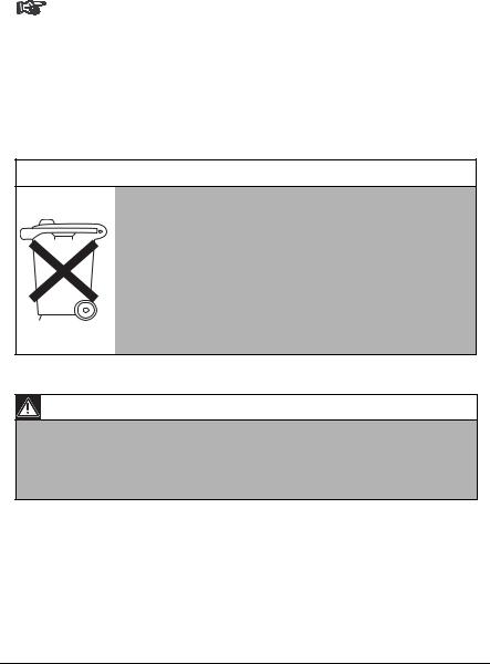
Only for EU countries
Do not dispose of electric tools together with household waste material!
In observance of European Directive 2002/96/EC on waste electrical and electronic equipment and its implementation in accordance with national law, electric tools that have reached the end of their life must be collected separately and returned to an environmentally compatible recycling facility.
Caution
The power supply unit must comply with EN/UL 60950 or equivalent safety standard. The power supply unit must be a SELV (Safety Extra Low Voltage) source with single fault protection. IEEE802.3af compliant power sources are SELV devices by default.
Bosch Security Systems | 2005-07 | V1.0

EN | x |
Dinion IP | Installation Manual |
Bosch Security Systems | 2005-07 | V1.0
Dinion IP | Installation Manual |
EN | 11 |
||
|
Introduction |
1 |
|
|
|
|
|
The Dinion IP camera is a high-performance smart surveillance color camera. It incorporates advanced digital signal processing for outstanding picture performance. The camera operates as a network video server and transmits video and control signals over data networks such as Ethernet LANs and the Internet.
The Dinion IP camera is easy to install and ready to use, and offers the best solution for demanding scene conditions. Features include:
•NightSense™ extends the low-light performance of the camera
•Enhanced video motion detection
•Video and data transmission over IP data networks
•Dual Streaming function for simultaneous encoding with two individually definable profiles
•Multicast function for simultaneous picture transmission to multiple receivers
•One analog composite video output CVBS (PAL/NTSC)
•Video encoding using international MPEG-4 standard
•Integrated Ethernet interface (10/100 Base-T)
•Remote control of all built-in functions via TCP/IP
•Password protection to prevent unauthorized connection or configuration changes
•Relay input for external sensor (such as door contacts)
•Event-driven, automatic connection (for example at switch-on and for alarms)
•Fast, convenient configuration using the integrated Web server and a browser
•Firmware update through flash memory
•Convenient upload and download of configuration data
Bosch Security Systems | 2005-07 | V1.0

Dinion IP | Installation Manual EN | 12
Type number overview
Type number |
NWC-0455-10P |
|
NWC-0455-20P |
Standard |
50 Hz |
|
60 Hz |
Supply voltage |
24 VAC or 12 VDC (use class 2 power supply) or |
||
|
PoE (IEEE 802.3af) |
||
CCD type |
|
1/3" |
|
|
|
|
|
Unpacking
Unpack carefully and handle the equipment with care. The packaging contains:
•DinionXF IP camera
•CS to C lens mount adapter
•CCD protection cap
•Spare lens connector (male)
•CD ROM
•Quick install instructions
Note
If equipment appears to have been damaged during shipment, repack it in the original packaging and notify the shipping agent or supplier.
System requirements
•Computer with Windows 2000/XP operating system, network access and Microsoft Internet Explorer web browser version 6.0 or later
or
•Computer with Windows 2000/XP operating system, network access and reception software, for example VIDOS or DIBOS 8.0
or
•MPEG-4 compatible hardware decoder from Bosch Security Systems (such as VIP XD) as a receiver and a connected video monitor
The minimum PC requirements are:
• Operating platform: A PC running Windows 2000 or Windows XP with IE6.0
Bosch Security Systems | 2005-07 | V1.0

Dinion IP | Installation Manual |
EN | 13 |
•Processor: 1.8 GHz Pentium IV
•RAM memory: 256 MB
•Video system: 128 MB video memory, 1024x768 display with 24-bit color
•Network interface: 100-BaseT
•DirectX: 9.0b
Note
Make sure the graphics card is set to 16-bit or 32-bit color depth and that Microsoft Virtual Machine or Java Virtual Machine is installed on your PC. To play back live video images, an appropriate MPEG ActiveX must be installed on the computer. If necessary, install the required software and controls from the product CD provided. If you need further assistance, contact your PC system administrator.
Overview of functions
The camera incorporates a network video server. Its primary function is to encode video and control data for transmission over an IP network. With its MPEG-4 encoding it is ideally suited for IP communication and for remote access to digital video recorders and multiplexers. The use of existing networks means that integration with CCTV systems or local networks can be achieved quickly and easily. Video images from a single camera can be simultaneously received on several receivers.
Wide dynamic range
The digital signal is automatically processed in the camera to optimally capture the detail in both the high and low light areas of the scene simultaneously, maximizing the information visible in the picture.
Power-over-Ethernet
Power for the camera can be supplied via a Power-over-Ethernet (IEEE 802.3af) compliant network cable connection. With this configuration, only a single cable connection is required to view, power and control the camera.
Bosch Security Systems | 2005-07 | V1.0

EN | 14 |
Dinion IP | Installation Manual |
Receiver
MPEG-4 compatible hardware decoders (for example VIP XD) can be used as a receiver. Computers with decoding software such as VIDOS or computers with the Microsoft Internet Explorer web browser installed can also be used as receivers.
Video encoding
The camera uses the MPEG-4 compression standard. Thanks to efficient encoding, the data rate remains low even with high image quality and can also be adapted to local conditions within wide limits.
Dual Streaming
Dual Streaming allows the incoming data stream to be encoded simultaneously according to two different, individually customized profiles. This creates two data streams per camera that can serve different purposes, for example one for local recording and one optimized for transmission over the LAN.
Multicast
In suitably configured networks, the multicast function enables simultaneous, real time transmission to multiple receivers. The prerequisite for this is that the UDP and IGMP V2 protocols are implemented on the network.
Configuration
The camera can be configured using a browser on the local network (Intranet) or from the Internet. Similarly, firmware updates and rapid loading of device configurations are also possible. Configuration settings can be stored as files on a computer and copied from one camera to another.
Snapshots
Individual video frames (snapshots) can be called up as JPEG images, stored on the hard drive or displayed in a separate browser window.
Backup
The browser application Livepage has an icon for saving the video images provided by the unit as a file on your computer's hard drive. Clicking this icon
Bosch Security Systems | 2005-07 | V1.0

Dinion IP | Installation Manual |
EN | 15 |
stores the video sequences and they can be replayed with the MPEG viewer from Bosch Security Systems included with the package.
Bosch Security Systems | 2005-07 | V1.0
EN | 16 |
|
Dinion IP | Installation Manual |
||
|
Connections |
2 |
|
|
|
|
|
|
|
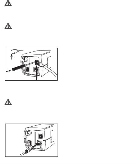
Power
Caution
Ensure that your power supply matches the rated voltage of your camera before installing.
Caution
Never supply power via the power connector when power is supplied via the Ethernet connection (PoE).
|
DC 12V |
10mm |
AC 24V |
VIDEO |
|
|
ALARM |
|
ETH |
•use a class 2 power supply
•24 VAC or 12 VDC
•push in the tabs to open the quick-connectors (these connections are not polarity sensitive).
•use AWG16 to 22 stranded wire or AWG16 to 26 solid wire; cut back 10mm (0.4") of insulation.
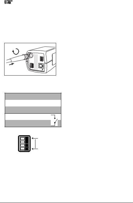
Network (and power)
Caution
Never supply power via the Ethernet connection (PoE) when power is supplied via the power connector.
DC 12V
AC 24V
VIDEO
ALARM
ETH
UTP Cat 5 RJ45
•connect the camera to a 10/100 Base-T network.
•use a shielded UTP Category 5 cable with RJ45 connectors.
•Power can be supplied to the camera via the Ethernet cable compliant with the Power-over- Ethernet (IEEE 802.3af) standard.
Bosch Security Systems | 2005-07 | V1.0
Dinion IP | Installation Manual |
EN | 17 |
Note
The multicolored LED under the Ethernet connection indicates Power (red), IP connection (green) and IP traffic (green flashing). It can be disabled in the Settings/Camera Settings/Installer options menu.
Video service monitor
DC 12V |
AC 24V |
VIDEO |
ALARM |
ETH |
•connect a service monitor to the composite video BNC connector to aid installation.
•a monitor connected close to the camera via this connection can also be used in parallel with remote PC viewing.
Alarm connector
Pin Alarm socket
1 Ground
2Alarm in
3 Relay out contact 1
4Relay out contact 2
Alarm
Pin 4
Pin 1
•Max. wire diameter AWG 22-28 for both stranded and solid.
•Default relay position n.o. (normally open), no alarm.
•Alarm output relay switching capability: Max voltage 30VAC or +40VDC. Max 0.5 A continuous, 10VA.
•Alarm in: TTL logic, +5V nominal, +40VDC max, DC coupled with 22kOhm pull-up to +3.3V.
•Alarm in: configurable as active low or active high.
•Max. 42V allowed between camera ground and each of the relay pins.
Lens mounting
The camera accepts CS-mount lenses with a lens protrusion of up to 5mm. C-mount lenses can be mounted using the lens adapter ring. DC-iris lenses are recommended for the best picture performance. The camera automatically detects the type of lens used and optimizes performance accordingly. A spare male lens connector is provided.
Bosch Security Systems | 2005-07 | V1.0
EN | 18 |
Dinion IP | Installation Manual |
Caution
To avoid damaging the CCD sensor when using a C-mount lens, make sure the supplied lens adapter ring is mounted onto the camera before mounting the lens.
Lenses weighing more than 0.5 kg (1.1lbs) must be separately supported.
Bosch |
Bosch |
Pin |
Video iris lens |
DC iris lens |
1 |
Supply (11.5V ±0.5, 50mA max.) |
Damp - |
2 |
Not used |
Damp + |
3 |
Video signal 1Vpp 1kOhm |
Drive + |
4 |
Ground |
Drive - |
|
|
|
Note
If a short circuit is detected on the lens connector, the on-screen display (OSD) failure message LENS SHORT CIRCUIT is shown. The lens circuit is automatically disabled to avoid internal damage. Remove the lens connector and check the pin connections.
Mounting the camera
The camera can be mounted from the top or bottom. The bottom mounting is isolated from ground. With outdoor scenes, a DC-iris lens is recommended.
Bosch Security Systems | 2005-07 | V1.0

Dinion IP | Installation Manual |
EN | 19 |
Caution
Do not point the camera/lens into direct sunlight.
Do not obstruct the free flow of air around the camera.
Note
The camera becomes quite warm when operating; this is normal. However, you should take this into account when touching the camera.
Bosch Security Systems | 2005-07 | V1.0
EN | 20 |
|
Dinion IP | Installation Manual |
||
|
Quick set-up |
3 |
|
|
|
|
|
|
|
The Dinion IP camera normally provides an optimal picture without the need for further adjustments. Configuration of the camera is carried out remotely via the network using a web browser. However, the camera also has an Installer menu in which basic installation settings (lens wizard, IP address) can be accessed. To view this menu connect a monitor to the composite video output of the camera.
Back focus adjustment
To optimize picture sharpness in both bright and low-level lighting, adjust the back focus. Use the camera's unique Lens Wizard. This ensures that the object of interest always remains in focus even when focusing at the maximum lens opening.
–When back focusing vari-focus lenses, adjust to obtain a sharp picture in both wide-angle and tele positions for both far and near focus.
–When back focusing zoom lenses, ensure the object of interest remains in focus throughout the entire zoom range of the lens.
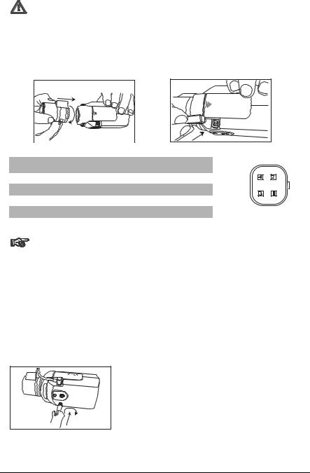
To adjust back focus:
1.Open the slide door at the side of the camera
2.Unlock the back focus locking button.
Bosch |
Bosch |
3. Turn the back focus adjustment as required.
Bosch Security Systems | 2005-07 | V1.0

Dinion IP | Installation Manual |
EN | 21 |
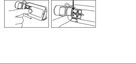
Bosch |
4. Lock the back focus locking button.
Accessing and navigating quick set-up menu
Five keys, located behind the side panel, are used for navigating through the quick set-up menu. To access the set-up menus, press the menu/select key (center). The main menu appears on the monitor.
Bosch |
Bosch |
How to use the navigation keys
Up key
Menu/select
Left key |
Right key |
|
Lock |
|
Down key |
•Press the menu/select key to access the menus or to move to the next or previous menu.
•Press the menu/select key for approximately 1.5 seconds to open the Installer menu.
•Use the up or down keys to scroll up or down through a menu.
Bosch Security Systems | 2005-07 | V1.0
 Loading...