


OD850 Outdoor
OD850 Outdoor Passive Infrared Detector/Microwave Intrusion Detector Installation Instructions ......................... |
Page 3 |
OD850 Gebruiksaanwijzing voor de installatie van de passieve infrarooddetector voor buitengebruik/microgolf |
|
inbraakdetector ...................................................................................................................................................... |
Pagina 4 |
Notice d’installation du détecteur à infrarouge passif/détecteur d’intrusion à hyperfréquence OD850 Extérieur ..... |
Page 5 |
OD850 AUSSENMELDER Passiver Infrarotmelder/Mikrowelleneinbruchsmelder Installationsanleitungen .............. |
Seite 6 |
Istruzioni di installazione del rilevatore a infrarossi passivi e del rilevatore a microonde antintrusione per esterni |
|
OD850 ................................................................................................................................................................... |
Pagina 7 |
Instruções de instalação do detector contra intrusos por Microondas/Infravermelhos passivos |
|
OD850 Exterior ...................................................................................................................................................... |
Página 8 |
Instrucciones de instalación del detector de intrusión por infrarrojos pasivos/microondas para |
|
exterior OD850 ............................................................................................................................ |
Página 9 |
OD850 / ....................................................................................... |
10 |
3 |
|
|
|
|
|
|
4 |
3-1 |
|
|
|
|
|
|
|
25 ft0 ft |
10 ft |
20 ft |
30 ft |
40 ft |
50 ft |
|
|
15 ft |
|
|
|
|
|
|
4-2 |
|
|
|
|
|
|
|
|
|
|
|
|
|
|
|
4-10 |
5 ft |
|
|
|
|
|
|
|
0 ft |
|
|
|
|
|
|
|
1.5 m |
|
|
|
|
|
|
|
4.5 m |
|
|
|
|
|
|
|
7.5 m |
|
|
|
|
|
|
|
0 m |
3 m |
6 m |
|
9 m |
12 m 15 m |
4-9 |
|
|
|
|
|
|
|
|
4-1 |
3-2 |
|
|
|
|
|
|
|
10 ft0 ft |
10 ft |
20 ft |
30 ft |
40 ft |
50 ft.m |
|
|
7 ft. |
|
|
|
|
|
2.13 m |
|
5 ft |
|
|
|
|
|
1.5 m |
|
0 ft |
|
|
|
|
|
0 m |
|
0 m 3 m 6 m 9 m 12 m 15 m |
|
||||||
|
|
|
4-3 |
|
|
|
4-6 |
|
|
|
|
|
|
4-4 |
4-8 |
|
|
|
|
|
|
|
|
|
|
|
|
|
|
|
4-5 |
4-7
5 |
6 |
|
5-1 |
1 2 3
- |
+ NC |
|
4 5 6 7 8 9
C |
|
T |
T |
NC C NO |
|||
|
|
|
|
|
|
|
|
© 20012 Bosch Security Systems, Inc.
F01U263662-02
Page 1 of 10
7 |
9 |
10 |
7-1 |
7-2 |
|
- +
10-1


 9-2
9-2
9-1
10-2
Bosch Security Systems, Inc. 130 Perinton Parkway Fairport, NY 14450-9199
www.boschsecuritysystems.com
© 2012 Bosch Security Systems, Inc.
F01U263662-02
Page 2 of 10
OD850 Outdoor
TriTech® Detector
1
Specifications
Dimensions: |
6.5 in. x 3.25 in. x 2.25 in. |
|
(16.5 cm x 8.25 cm x 5.7 cm) |
Input Power: |
10 VDC to 15 VDC @ 22 mA |
|
standby. Maximum current 62 mA. |
|
Use only a Listed limited-power |
|
source. |
Standby |
No internal standby battery. |
Power: |
Standby power must be provided |
|
by a Listed limited-power source. |
|
For UL Certificated installations, |
|
4 h (88 mAh) standby power must |
|
be provided by the control panel or |
|
by a Listed burglary power source. |
Alarm |
Form “A” normally closed (NC), |
Relays: |
supervised alarm contact opens |
|
on alarm. Form “C” unsupervised, |
|
timed relay contact transfers on |
|
alarm and follows an installer |
|
programmable timer. |
Contact |
2.5 W, 100 mA maximum, 25 VDC |
Ratings: |
maximum, ,20 Ohms closed. |
|
Note: For resistive loads only, do |
|
not use with capacitive or inductive |
|
loads. |
Temperature |
The temperature range is -31°F |
Range: |
to +140°F (-35°C to +60°C) for |
|
all installations including UL |
|
Certificated installations. |
Microwave |
OD850-F1: 10.525 GHz (UL |
Frequency: |
Listed) |
|
OD850-F2: 10.588 GHz |
Coverage: |
50 ft by 50 ft (15 m by 15 m) |
Tamper: |
NC (with cover on). Contacts |
|
rated 125 mA maximum, 25 VDC |
|
maximum. Connect tamper circuit |
|
to a 24-hour protection circuit. |
IP Rating: |
54 |
Options: |
B335 Low Profile Swivel Mount |
|
Bracket (supplied), B328 Swivel |
|
Mount Bracket, B338 Ceiling |
|
Mount Bracket, Pole Mount |
|
Bracket (supplied). |
|
Note: Misaligning the detector in |
|
these brackets can reduce the |
|
detector’s range and increase the |
|
dead zone area. |
Compliance
Note: This equipment has been tested and found to comply with the limits for a Class B digital device, pursuant to part 15 of the FCC rules. These limits are designed to provide reasonable protection against harmful interference in a residential installation. This equipment generates, uses and can radiate radio frequency energy and, if not installed and used in accordance with the instructions, may cause harmful interference to radio communications. However, there is no guarantee that interference will not occur in a particular installation. If this equipment does cause harmful interference to radio or television reception, which can be determined by turning the equipment off and on, the user is encouraged to try to correct the
interference by one or more of the following measures:
-Reorient or relocate the receiving antenna.
-Increase the separation between the equipment and receiver.
-Connect the equipment into an outlet on a circuit different from that to which the receiver is connected.
-Consult the dealer or an experienced radio/TV technician for help.
This device complies with Part 15 of the FCC Rules. Operation is subject to two conditions:
1.This device cannot cause harmful interference.
2.This device must accept any interference received, including interference that might cause undesired operation.
Changes or modifications not expressly approved by Bosch Security Systems, Inc. can void the user’s authority to operate the equipment.
This product is intended for use in the following countries within the European Union and in other countries outside of the European Union: OD850-F1: Austria, Belgium, Denmark, Finland, Greece, Luxembourg, Netherlands, Norway, Spain, Sweden, Italy
OD850-F2: France, United Kingdom
EN 50130-5 Environmental Class II
IP30 IK04 (EN 60529, EN 62262)
N663
2
Installation Considerations
Never install the detector where the PIR or microwave is in constant alarm (LED on). The LED is off when properly installed.
Point away from traffic.
Avoid installing where hanging signs, trees or other objects that the wind can move are within the coverage pattern or where wildlife might move within the coverage pattern.
The mounting surface must be solid and vibration-free.
UL Listing Requirements
The unit shall only be installed outdoors for primary protection in high security installations where unwanted alarms would be tolerated. Otherwise, the outdoor device should be used for supplementary protection only, and be connected to a trouble zone or to a zone that is not programmed for off-premises transmission.
Warning!
-Apply power only after all connections are made and inspected. Do not coil excess wiring inside detector.
-Do not connect any terminal to any power supply providing more than 25 VDC.
SELV
Connect all wiring to a Safety Extra-Low Voltage (SELV) circuit only.
3
Coverage Patterns
 Microwave coverage
 PIR coverage
 Look-down zone
Note: When choosing the appropriate mounting height for your application (particularly, when the terrain is not level) the upper finger is the strongest and responds more quickly to an intruder’s presence. Every finger shown in the top view (3-1) has the same side view (3-2) configuration.
5
Tamper Options
The unit has a built-in cover tamper that signals when the detector unit (4-9) separates from the
mounting plate (4-1). The unit can also be installed so the tamper signals if the entire unit is pulled away from the surface on which it is mounted.
Note: The wall and cover tamper option are only available when the unit is surface mounted. The cover tamper is available with all mounting options.
Determine whether the tamper switch is to be used as a cover tamper or a wall and cover tamper:
-Wall and cover tamper: Use the appropriate screw to fasten the mounting plate tamper section (5-1) to the wall.
-Cover tamper: Do not attach the mounting plate tamper section (5-1) to the wall.
6
Wiring
Terminal |
Label |
Function |
|
1 |
(-) |
Input power: Use at least a |
|
|
|
22 AWG (0.8 mm) wire pair |
|
2 |
(+) |
||
between the unit and the |
|||
|
|
||
|
|
power source. |
|
3 |
NC |
Alarm relay |
|
4 |
C |
|
|
5 |
T |
Tamper |
|
6 |
T |
|
|
7 |
NC |
Timed alarm relay contacts |
8C
9NO
CAUTION!
Only apply power after all connections have been made and inspected. Do not coil excess wiring inside detector. Use no smaller than #22 AWG (0.8 mm) wire in the terminal strip.
8
LED Display
LED Indicator |
Condition |
||
Green |
Steady |
PIR alarm |
|
Flashing |
Microwave alarm |
||
|
|||
Red |
Steady |
Dual alarm (both technologies) |
|
Flashing |
Power-up |
||
|
|||
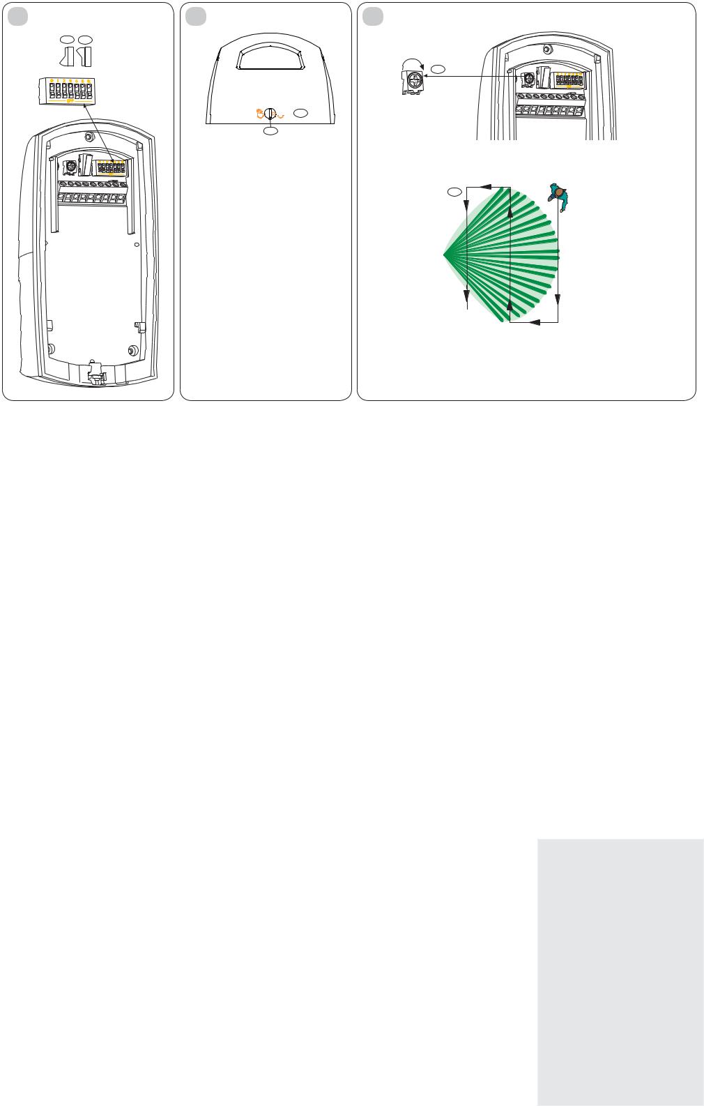
9
Attaching Detector to Mounting Plate
1.When all wiring is connected to the detector but not to the power supply and all the settings are made, slide the detector unit (4-9) onto the mounting plate (4-1) and down until it is firmly seated. Avoid pinching the wires.
2.With a small flat head screwdriver, turn the locking cam (9-1) 180o to lock (9-2) the detector unit to the mounting plate. Avoid excessive force.
4
Mounting
1.Select a mounting location. Mount the sensor where an intruder is most likely to cross the coverage pattern.
2.Mount the detector 7 ft to 9 ft (2.1 m to 2.7 m) above the ground. Recommended: 7 ft (2.1 m)
Note: Mounting height recommendations are based on level surfaces. If the terrain is not level, adjust the mounting height and detector angle to provide the best coverage.
3.Slide the mounting plate down (4-1) until you hear a click, and remove it from the cover.
4.Mount the mounting plate using one of these options:
Note: Do not remove the waterproof label from the mounting plate (4-2). Push the mounting screws or wiring knockouts through the label as needed.
-Surface mount using a single-gang electrical box.
1.Install a single-gang electrical box at the detector location.
2.Attach the mounting plate (4-3) to the single-gang box with the appropriate screws.
-Surface mount without an electrical box.
1.Select an appropriate location.
2.Using the mounting plate (4-1) as a template, mark the location of the mounting screws and the wire run.
3.Attach the mounting plate (4-1) to the wall with the appropriate screws.
-Surface Mount using the supplied B335 Bracket or an optional bracket. Use the bracket’s instructions to attach the bracket to the appropriate mounting surface.
- Attach the B335 Bracket to the mounting plate. (4-4). - Attach the B328 Bracket to the mounting plate. (4-5). - Attach the B338 Bracket to the mounting plate. (4-6).
-Pole Mount using the supplied bracket.
Note: Do not mount to fence posts that might sway in the wind.
-Attach the bracket (4-7) to the mounting plate (4-8) using the appropriate screws and mounting holes.
-Two hose clamps (not supplied) large enough to fit around the pole are recommended for fastening the detector mounting plate to the pole.
7
DIP Switch Configuration
(7-1) On
(7-2) Off
Switch |
Feature |
Description |
Switch Position |
|
|||
0 |
LED |
Determines if the LED lights during |
ON: LED enabled |
||||
|
Disable |
alarm situations. |
OFF: LED disabled |
||||
|
|
Default factory setting: ON |
|
|
|
|
|
1 |
PIR |
Standard: Minimizes false alarms. |
ON: Standard |
|
|||
|
Sensitivity |
Tolerates environmental extremes |
OFF: Intermediate |
||||
|
|
Intermediate: Use where an intruder |
|
|
|
|
|
|
|
might cover only a small portion of the |
|
|
|
|
|
|
|
protected area. |
|
|
|
|
|
|
|
Tolerates normal environments. |
|
|
|
|
|
|
|
Note: The detector is shipped in |
|
|
|
|
|
|
|
Standard Mode. |
|
|
|
|
|
2 and 3 |
Timed |
Form “C,” unsupervised, timed relay |
SW2 |
|
SW3 |
|
Relay Activation Time |
|
Relay |
contact that transfers 1 sec after an |
|
|
|
|
|
|
OFF |
|
OFF |
|
2 sec |
||
|
Outputs |
alarm. It follows a user-selectable |
|
|
|||
|
ON |
|
OFF |
|
1 min |
||
|
|
timer. The time expires at the time set |
|
|
|||
|
|
OFF |
|
ON |
|
5 min |
|
|
|
after the last alarm. It resets on each |
|
|
|||
|
|
new alarm. |
ON |
|
ON |
|
10 min |
4 |
AND/OR |
Determines if the detector alarms |
ON: AND Mode (recommended) |
||||
|
Mode |
in the AND mode (when both |
OFF: OR Mode, you must also cut the |
||||
|
|
technologies simultaneously sense an |
jumper (4-10). |
|
|||
|
|
alarm condition) or in the OR mode |
|
|
|
|
|
|
|
(when either the PIR or Microwave |
NOTE: |
|
|
|
|
|
|
technology senses an alarm state). |
OR Mode is not compliant with |
||||
|
|
Note: The OR mode is not |
EN50130-5 |
|
|||
|
|
recommended for most installations. |
|
|
|
|
|
|
|
The OR mode provides faster |
|
|
|
|
|
|
|
detection in some conditions. It |
|
|
|
|
|
|
|
can also increase the likelihood of |
|
|
|
|
|
|
|
nuisance alarms because the detector |
|
|
|
|
|
|
|
activates the alarm relay based on |
|
|
|
|
|
|
|
input from a single technology. |
|
|
|
|
|
5Not used
6Not used
10
Walk Test
Note: Ensure the detector is fastened to the mounting plate and all wiring is connected and powered before beginning the Walk Test.
Note: Ensure the LED Disable (SW0) is on (refer to Section 7 DIP Switch Configuration).
Note: To avoid false alarms, set the microwave range (10-1) to its minimum setting before starting the Walk Test.
 Microwave coverage
 PIR coverage
1.Wait at least 2 minutes after power up to start the Walk Test.
The LED flashes red until the detector stabilizes and no movement is detected for 2 seconds.
2.Watch the LED as you walk towards the edge of the pattern (10-2). The LED lights at the outside edge of the coverage range.
3.Repeat Step 3 from different directions until you adequately verify the coverage pattern.
The green LED lights, identifying the PIR pattern edge.
The green LED flashes, identifying the microwave pattern edge.
4.Repeat Step 3 from the opposite side.
5.If the required range is not achieved, increase the microwave adjustment (10-1) by turning it clockwise slightly.
6.Repeat the walk test and adjustments until you reach the farthest edge of coverage needed.
Bosch Security Systems, Inc. 130 Perinton Parkway Fairport, NY 14450-9199
www.boschsecuritysystems.com
TriTech® is a registered trademark of Bosch Security Systems, Inc. in the United States.
© 2012 Bosch Security Systems, Inc.
F01U263662-02
Page 3 of 10
 Loading...