


MDCI8-1

Installation manual
6 720 874 421 (2017/04) ZA
Before using your air conditioning unit, please read this manual carefully and keep it for future reference.
Mini VRF Heat Pump Outdoor Unit
Climate 5000 VRF
MDCI series, SINGLE PHASE
6 720 874 421 (2017/04) ZA Mini VRF Heat Pump Outdoor Unit
2 | PRECAUTIONS
1. PRECAUTIONS
■ Before installing this equipment, ensure all local and national
regulations are complied with.
■ Read these ”PRECAUTIONS” carefully prior to Installation.
■ Before performing maintenance ensure the electrical power
circuit has been turned off. Failure to do so will result in serious
injury.
■ Ensure both the installation manual and the owners manual are
kept together and handed to the customer upon completion.
CAUTION
New Refrigerant Air Conditioner Installation
CAUTION
An all-pole disconnection device which has at least 3 mm separation
distance in all poles and a residual current device (RCD) shall be
incorporated into the fixed wiring in accordance with national wiring
regulations.
WARNING
The appliance shall be installed in accordance with national wiring
regulations.
When installing, ensure communication and electrical power supply
cables do not touch the copper pipework.
The temperature of the refrigeration circuit will be high and may damage
cables.
An all-pole disconnection device which has at least 3 mm separation
distance between all poles and a residual current device(RCD)with the
rating of above 10 mA shall be incorporated in the fixed wiring according
to the national regulations.
Ensure only qualified persons carry out works on this equipment.
Incorrect installation may result in can damage or serious injury.
Do not modify this unit by removing any of the safety guards or bypassing any of the safety interlock switches.
Exposing the unit to water or other moisture before installation may
cause a short-circuit on the electrical components.
Do not store the unit where it can be exposed to water or moisture.
After unpacking, ensure you inspect the unit for damage.
When installing this equipment, anti vibration pads must be installed to
stop vibration.
To avoid personal injury (with sharp edges), care must be taken when
handling components.
Installation of the unit must be done as per the instructions set in this
installation manual.
Incorrect installation may result in component failure, damage to property
or injury.
When the air conditioning unit is installed in a small room, provide
appropriate measures to ensure that the concentration of refrigerant
leakage in the room does not exceed the thickness level should a leak
occur.
Install the air conditioning unit securely in a location where the base can
sustain the weight adequately.
If refrigerant gas has leaked during the installation work, ventilate the
room immediately.
If the leaked refrigerant gas comes in contact with a naked flame, noxious gas
may be generated..
After installation is complete, ensure a satisfactory strength/tightness
test has been performed to ensure there is no refrigerant gas leakage.
Electrical work must be performed by a qualified electrician in
accordance with the Installation Manual.
Ensure equipment is grounded.
Do not connect ground wires to gas pipes, water pipes, lightning rods or
ground wires for telephone cables.
Conform with national wiring standards.
Inappropriate grounding may cause electric shock.
Do not install the air conditioner in a location where it is at a risk of
exposure to a combustible gas.
CONTENTS PAGE
1. PRECAUTIONS .................................................................... 2
2. ATTACHED FITTINGS ........................................................... 3
3. OUTDOOR UNIT INSTALLATION ............................................ 3
4. INSTALLING THE CONNECTIVE PIPEWORK ............................5
5. ELECTRICAL WIRING ........................................................... 9
6. TEST RUNNING ................................................................. 12
7. PRECAUTIONS ON REFRIGERANT LEAKAGE ........................ 12
Mini VRF Heat Pump Outdoor Unit 6 720 874 421 (2017/04) ZA
ATTACHED FITTINGS | 3
2. ATTACHED FITTINGS
Ensure all fittings are supplied with unit prior to installation.
NAME SHAPE QUANTITY
INSTALLATION FITTINGS
1. Outdoor unit installation manual 1
2. Outdoor unit owner’s manual 1
3. Indoor unit owner’s manual 1
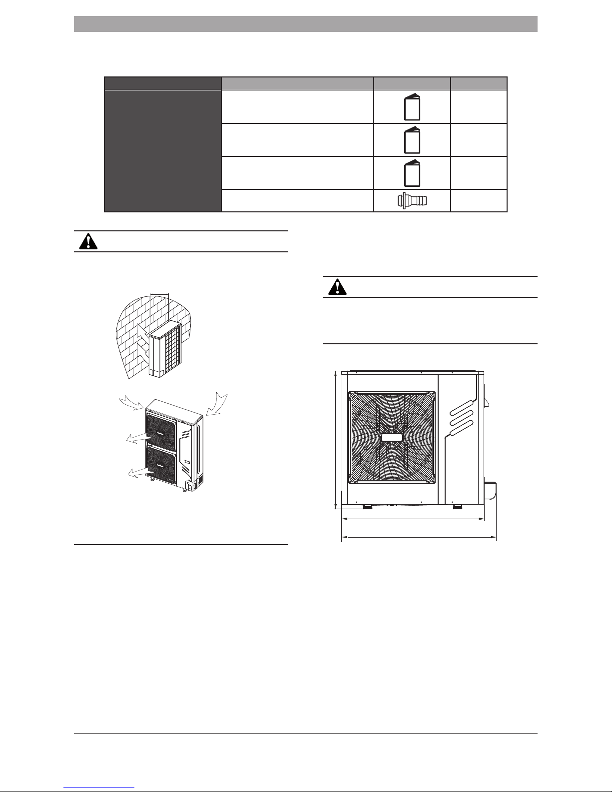
4. Outflow connecting tube 1
CAUTION
■ Install the unit so that its discharge port faces to the wall of the
building. Keep a distance of 2000 mm or more between the unit and
the wall surface.
2000
Fig. 2-1
Strong
wind
Strong
wind
Fig. 2-2
■ Do not install the unit in the following locations as component failure
will occur.
• Where machine oil is present.
• Where sulphuric acid is present.
• Where high frequency radio waves are likely to be generated.
3. OUTDOOR UNIT INSTALLATION
3.1 Installation location
The following locations may cause component failure.
• Where there is a combustible gas leakage.
• Where there is oil surrounding.
• Where there is salty air surrounding.
• Where there is caustic gas (the sulfide, for example) existing in
the air.
• A location where discharge air will affect others.
• A location where noise affects neighbors.
• A location that is too weak to bear the weight of the unit.
• A location which is uneven.
• A location where there is insufficient ventilation.
• Near a private power station or high Frequency equipment.
• A location where the indoor/outdoor unit, power cord and
connecting wires are less than 1m away from a tv or radio.
• Installing the unit where there is insufficient maintenance access.
CAUTION
Keep the indoor and outdoor power supply wiring and communication
wiring at least 1 meter away from televisions and radios. This is to
prevent image and noise interference. In certain circumstances, 1m
may not be sufficient.
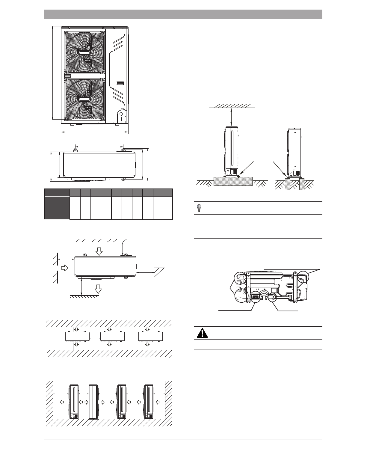
3.2 Installation clearances (Unit:mm)
H
G
A
Fig. 3-1
6 720 874 421 (2017/04) ZA Mini VRF Heat Pump Outdoor Unit
4 | OUTDOOR UNIT INSTALLATION
H
A
Fig. 3-2
B
C
D
E
F
Fig. 3-3
MODEL (kW) A B C D E F G H Fig.
8/10.5 990 624 380 339 396 366 1073 966
Fig. 3-1
Fig. 3-3
12/14/16/18 1280 600 366 320 400 360 – 1327
Fig. 3-2
Fig. 3-3
• Single unit installation
>300
>600
>300
>2000
(Wall or obstacle)
Maintain
channel
Air outlet
Air inlet
Air inlet
Fig. 3-4
• Parallel connection of two or more units.
>600
>2000
>300
Fig. 3-5
• Parallel connection for units facing each other.
>2000 >500 >3000 >3000 >300
Fig. 3-6
3.3 Handling and installation
• Caution must be taken when handling the outdoor unit, the
weight is not in the centre of the unit. The unit is heavier on the
front right side. For lifting advice consult HSE and use specified
lifting equipment.
• Do not touch the fan blades. The fan blades are sharp and could
cause an injury.
• When handling the unit, ensure you do not lean the unit more than
45 degrees as this will cause internal damage to the compressor.
• Fasten the feet of this unit with bolts firmly to prevent it from
toppling over. (Refer to Fig.3-7)
>60c m
Fix with bolt
Fig. 3-7
NOTE
All the pictures in this manual are for illustration purposes only. The
illustrations may be slightly different from the air conditioning unit you have
purchased (dependent on model).
3.4 Condensate Outlet
There are four condense water outlets on the body of the unit shown on
the figure below.
Reserve water outlet
Reserve water outlet
Water Outlet
Outlet for power and connecting pipes
Remove knockout
if required
(With rubber stopper)
Fig. 3-8
CAUTION
When installing the outdoor unit, consider the drainage points.
Mini VRF Heat Pump Outdoor Unit 6 720 874 421 (2017/04) ZA
INSTALLING THE CONNECTIVE PIPEWORK | 5
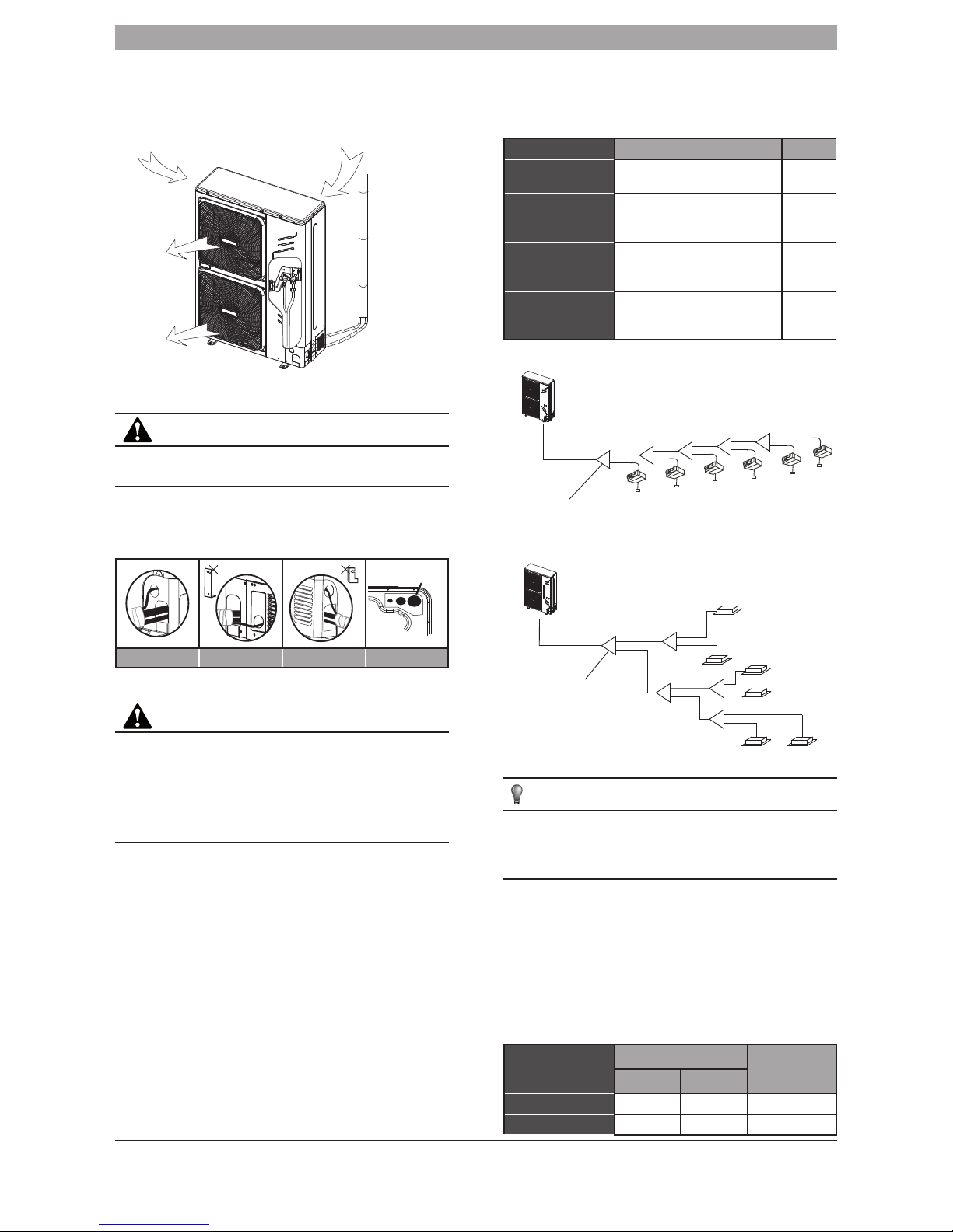
4. INSTALLING THE CONNECTIVE
PIPEWORK
Ensure the pipe limitations in this manual have been complied with.
Failure to do so will cause the unit to malfunction.
Strong
wind
Strong
wind
Fig. 4-1
4.1 Refrigerant pipework
CAUTION
To prevent the refrigerant pipework from oxidising, it is necessary to purge
nitrogen through the piping whilst brazing.
The outdoor unit can be piped in various ways. The pipes can run from the
back, front and under the unit. Remove knock outs where appropriate.
Table 4-1
Fat pipe
Front Side Back Undersurface
CAUTION
When piping from the side please remove the metal L shape plate, otherwise
cabling will not fit.
When piping from the back, ensure you take out the rubber support blanket
beside the inner outlet pipe.
When piping from the front side cut out the front knock out hole.
When piping the undersurface: Remove the knockouts from inside to outside.
Ensure you use the correct size hole when you are piping the unit.
4.2 Pipework Insulation
■ All refrigerant pipework must be correctly insulated in accordance
with national standards.
4.3 Connecting method
■ Select refrigerant pipe
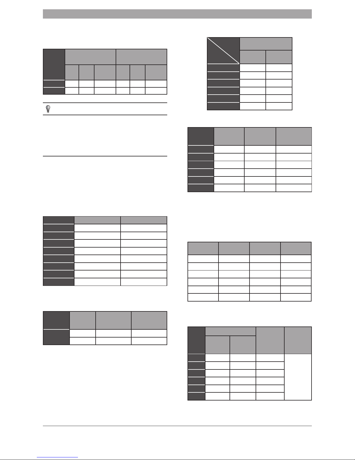
Table 4-2
Pipe definition Pipe location Code
Main pipe The pipe between outdoor unit to
the first branch of indoor unit.
L1
The main pipes for
indoor unit
The pipe after the first branch
which does not connect directly to
the indoor unit.
L2~L5
The branch pipes for
indoor unit
The pipe after the branch which
does not connect directly to the
indoor unit.
a, b, c,
d, e, f
Indoor unit branch
joint assembly
The branch connector, where the
main pipe connects to the branch
pipe supplying the indoor units.
A, B, C,
D, E
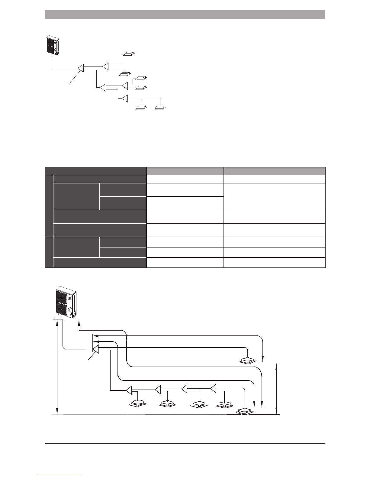
• The first connection method
a
b
c
e
f
d
L1
L2
L3
L4
L5
A
B
C
D
E
The First pipe branch
Outdoor Unit
Fig. 4-4
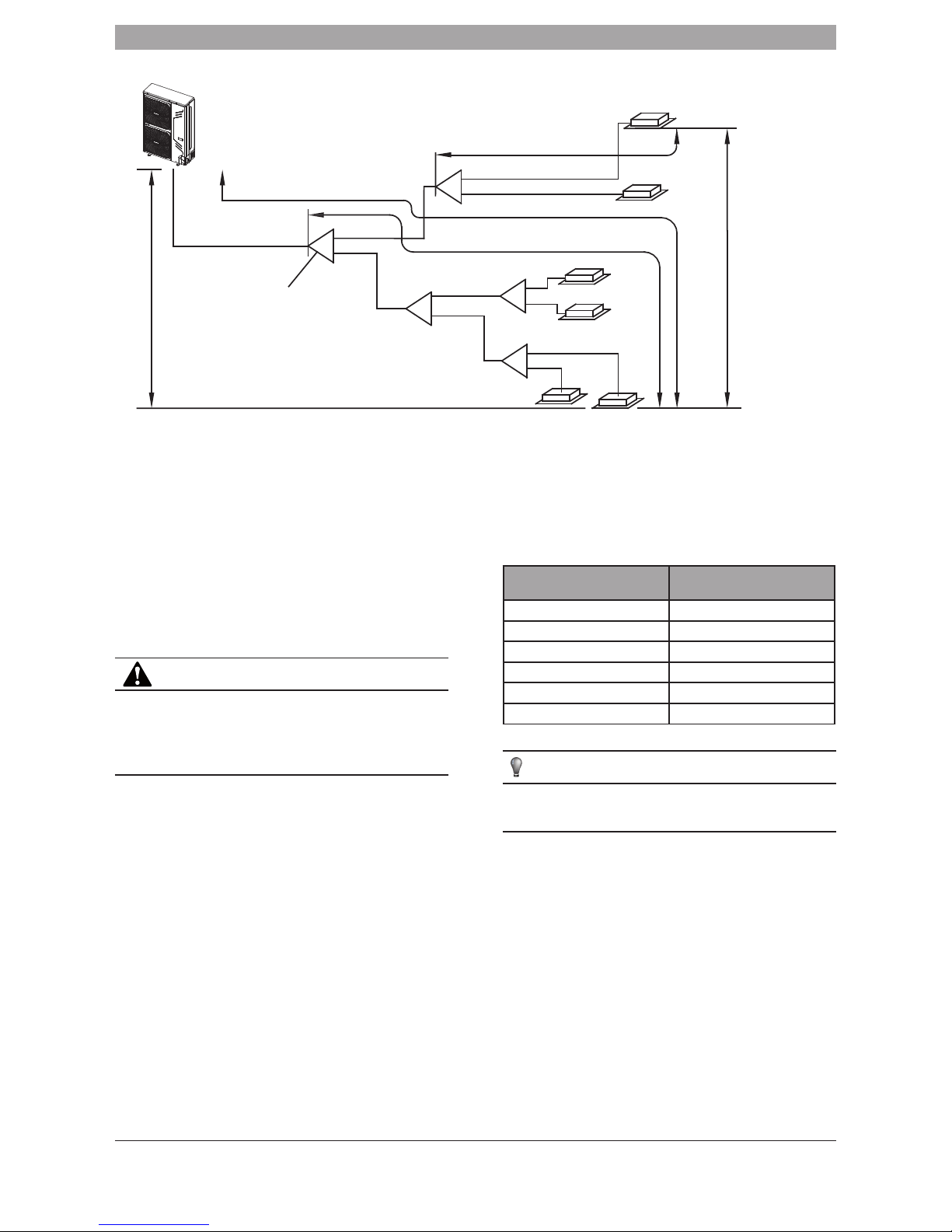
• The second connection method
N1
(28)
N
3
(28)
N
5
(28)
N
6
(22)
N
2
(28)
N
4
(28)
A
B
D
E
C
a
b
c
e
f
d
L
1
L2
L5
L3
L4
The First pipe branch
Outdoor Unit(Take Model 160 for example)
Intdoor Units
Fig. 4-5
NOTE
• When the distance between the first branch and the last branch is
greater than 15m, refer to installation method 2..
• The pipe between the indoor unit to the closest branch must be less
than 15 m.
4.4 Confirmation for the diameters of indoor unit
connecting pipes
■ Size of main pipe and corresponding branch joint and branch header
1) R410A Indoor unit connecting pipe diameters 4-3.
2) Example 1: In the Fig.4-5. The downstream inner units of L2, and
its total capacity is 28×2=56, refer to the Table4.4, the air/liquid
side for L2 is Ø15.9/Ø9.5.
Table 4-3 R410A Indoor unit connecting pipes diameters
Total capactiy of the
downstream inner
units
Main pipe size (inches) Branch Pipe
Gas pipe Liquid pipe
A<166 Ø15.9 Ø9.5 IDU - 01
166≤A<230 Ø19.1 Ø9.5 IDU - 01
6 720 874 421 (2017/04) ZA Mini VRF Heat Pump Outdoor Unit
6 | INSTALLING THE CONNECTIVE PIPEWORK
4.5 Confirmation for the diameters of outdoor unit
connecting pipes
Table 4-4 R410A outdoor unit connecting pipes diameters
Total capactiy
of the
outdoor units
Main pipe size when the total
equivalent pipework length of liquid
+ gas side is <90 m
Main pipe size when the total
equivalent pipework length of liquid
+ gas side is ≥90 m
gas
side
(inches)
liquid
side
(inches)
The first Line
Branch Pipe
gas
side
(inches)
liquid
side
(inches)
The first Line
Branch Pipe
A<160 Ø15.9 Ø9.5 IDU - 01 Ø19.1 Ø9.5 IDU - 01
160≤A<230 Ø19.1 Ø9.5 IDU - 01 Ø22.2 Ø9.5 IDU - 02
NOTE
• When installing branch joints ensure there is at least 0.5 m of straight
pipe before and after the branch joint;
• The straight distance between branchpipes must be at least 0.5 m;
• The straight distance where the branch pipes connect to the indoor
unit must be at least 0.5 m;
• Branch header must be connected with the indoor units directly,
further branch connections are not allowed.
• Select branch joint
• Select the branch joint required by the total designed capacity of the
indoor units which it connects to. If this capacity is more than that of
the outdoor unit, then select the connection according to the outdoor
unit.
• The selection of branch header depends on the quantity of branches
it connects to.
■ Connection method
Table 4-5
Gas side Liquid side
8kW Flaring Flaring
10.5kW Flaring Flaring
12kW Flaring Flaring
14kW Flaring Flaring
16kW Flaring Flaring
18kW Flaring Flaring
Indoor unit Flaring Flaring
Branch pipe Brazing or Flaring Brazing or Flaring
■ Pipework sizes at the branch pipe
Table 4-6
Refrigerant Indoor Unit
Capacity
A(x100W)
Gas Side (Ø) Liquid Side (Ø)
R410A A≤45 12.7(Flaring nut) 6.4(Flaring nut)
A≥56 15.9(Flaring nut) 9.5(Flaring nut)
■ Pipe diameter of the connections onto the outdoor unit.
Table 4-7
Pipework
side
MODEL
(kW)
Pipe diameter of outdoor
unit‘s connections (inches)
Gas Side Liquid Side
8 Ø15.9 Ø9.5
10.5 Ø15.9 Ø9.5
12 Ø15.9 Ø9.5
14 Ø15.9 Ø9.5
16 Ø19.1 Ø9.5
18 Ø19.1 Ø9.5
Table 4-8
Outdoor Unit
(kW)
Capacity of
Outdoor unit
(horse power)
Maximum
Quantity of
Indoor units
Sum Capacity of
Indoor unit (horse-
power)
8 2.5 4 45%~130%
10.5 3 5 45%~130%
12 4 6 45%~130%
14 5 6 45%~130%
16 6 7 45%~130%
18 6.5 9 45%~130%
When connecting more than one indoor unit, the largest capacity connected
should be less than 8KW.
When the total capacity of the indoor units is greater than 100% of the
outdoor units capacity, ensure you turn the indoor units on one by one one.
Too many at once will cause damage to the compressor.
When the total capacity of the indoor units is greater than or equal to
16.8 kW, the size of primary gas pipe should be enlarged from Ø16 to Ø19.
Table 4-9
Capacity
ranking
Capacity
(horsepower)
Capacity
ranking
Capacity
(horsepower)
18 0.6 80 2.5
22 0.8 10.5 3
28 1 120 4
36 1.25 140 5
45 1.7 160 6
56 2
■ When the outdoor unit connects to one indoor unit
Table 4-10
MODEL
(kW)
The max height drop (m)
The length of
refrigerant pipe
(m)
The number
of bends
When out-
door
unit is top
When
outdoor unit is
bottom
8 25 20 50
less than 10
10.5 25 20 50
12 25 20 50
14 25 20 50
16 25 20 50
18 25 20 50
Mini VRF Heat Pump Outdoor Unit 6 720 874 421 (2017/04) ZA
INSTALLING THE CONNECTIVE PIPEWORK | 7
4.6 Illustration
N1
(28)
N
3
(28)
N
5
(28)
N
6
(22)
N
2
(28)
N
4
(28)
A
B
D
E
C
a
b
c
e
f
d
L
1
L2
L5
L3
L4
Outdoor Unit((Take Model 160 For Example)
The First Branch Pipe
Indoor units
Fig. 4-6
Caution: Ensure both liquid and gas pipework combined does not exceed
90m.
• Indoor unit branch pipe
Inner branch pipes are a~f, for size selection please refer to Table4-6.
Note: The Maximum length of the branch pipe should not exceed
more than 15m.
• The main pipes for the indoor units and the indoor unit branch pipe
components.
■ The downstream inner units of the main pipe L2 are N1,
N2, and its total capacity is 28×2=56, the size of pipe
L2 is Ø15.9/Ø9.5, and the branch pipe B should be
IDU - 01.
■ The downstream inner units of the main pipe L4 are N3,
N4, and its total capacity is 28×2=56, the size of pipe
L4 is Ø15.9/Ø9.5, and the branch pipe D should be
IDU - 01.
■ The downstream inner units of the main pipe L5 are N5,
N6, and its total capacity is 28+22=50, the size of pipe
L5 is Ø15.9/Ø9.5, and the branch pipe E should be
IDU - 01.
• Allowable length and height difference of refrigerant pipes
Table 4-11
Permitted value Pipework
Pipe Length
Total Pipe Length (Actual) ≤100 m L1+L2+L3+L4+L5+a+b+c+d+e+f
Maximum Pipework (L)
Actual Length
≤45 m (8 kW, 10.5 kW)
≤60 m (12 kW, 14 kW, 16 kW, 18kW)
L1+L2+L3+L4+L5+f
(The first connection method)
Equivalent Length
≤50 m (8 kW, 10.5 kW)
≤70 m (12 kW, 14 kW, 16 kW, 18kW)
or L1+L3+L5+f
(The second connection method)
Pipe Length (from the first line branch pipe
to furthest indoor unit)(m)
≤20 m L2+L3+L4+L5+f (The first connection method)
or L3+L5+f (The second connection method)
Pipe Length (from the nearest branch pipe
equivalent length(m)
≤15 m
a, b, c, d, e
Drop Height
Indoor Unit-Outdoor
Unit Drop Height (H)
Outdoor Unit up
≤30 m
______________
Outdoor Unit Down
≤20 m
______________
Indoor Unit to Indoor Unit Drop Heihgt (H)
≤8 m
______________
Note: When the distance of the refrigerant pipework is over 90m, the system will decrease in capacity. You must increase the gas pipe by one size.
• The first connection method
Drop height between indoor unit and outdoor unit
Indoor Unit
The First Line Branch Pipe
Outdoor unit
a
A
L2
L1
B
C
D
E
L3 L4 L5
b
c
d
e f
Pipe length(From the nearest branch pipe equivalent length)
Maximum pipe equivalent length
(From the first line branch pipe) Maximum pipe equivalent length
Indoor Unit to Indoor
Unit Drop height
Fig. 4-7
6 720 874 421 (2017/04) ZA Mini VRF Heat Pump Outdoor Unit
8 | INSTALLING THE CONNECTIVE PIPEWORK
• The second connection method
Indoor unit
a
N
1
3
N
5
N
6
N
2
N
4
N
Outdoor unit
A
B
D
E
C
b
c
e
f
d
1
L
2
L
5
L
3
L
4
L
Drop height between indoor unit and outdoor unit
Maximum equivalent pipe length
Equivalent pipe length to the nearest
branch.
(From the first line branch pipe)
Maximum equivalent pipe length
Indoor Unit to Indoor Unit Drop height
The First Line Branch Pipe
Fig. 4-8
4.7 Removing The Contaminants in the Pipework
Ensure pipework is clear from any water or dirt prior to connecting onto the
outdoor unit.
When cleaning pipework, use nitrogen to flush through the system. Do not
use refrigerant or water to clean the pipework.
4.8 Strength/Tightness Test
Pressure test the system with nitrogen to 44kgf/cm2. Ensure a 24 hour
strength test has been completed for all new installations. For guidance on
tightness testing for existing installations, please refer to F Gas Regulations.
CAUTION
1 Pressured nitrogen [4.3 MPa (44kg/cm2) for R410A] should be used
for strength testing.
2 The high pressure/low pressure valves must be closed when applying
pressured nitrogen.
4.9 Vacuuming the installation
• Use a vacuum pump to create the vacuum. do not use refrigerant to
expel air.
• Vacuuming should be done on liquid, gas and oil balance pipework.
4.10 Refrigerant Amount to be Added
Calculate the additional refrigerant to be added according to the diameter
and the length of the liquid side pipe.
• When the outdoor unit connects 1 indoor unit:
Table 4-12
Liquid Side Pipework
Diameter
Refrigerant to be Added
Per Meter Of Pipework
Ø6.4 0.022 kg
Ø9.5 0.054 kg
Ø12.7 0.110 kg
Ø15.9 0.170 kg
Ø19.1 0.260 kg
Ø22.2 0.360 kg
NOTE
Additional refrigerant volume of divergent pipe is 0.1 kg per meter
(Consider the liquid side of divergent pipe only)
 Loading...