


Robert Bosch GmbH
Geschäftsbereich Elektrowerkzeuge
D-70745 Leinfelden-Echterdingen
Germany
www.bosch-pt.com
2 609 140 582 (2008.07) T / 269 XXX
DLE 40 Professional
de Originalbetriebsanleitung en Original instructions
fr Notice originale es Manual original pt Manual original
it Istruzioni originali nl Oorspronkelijke
gebruiksaanwijzing
da Original brugsanvisning sv Bruksanvisning i original no Original driftsinstruks fi Alkuperäiset ohjeet
el Πρωτότυπο οδηγιών χρήσης tr Orijinal işletme talimat
pl Instrukcją oryginalną
cs Původním návodem k používání sk Pôvodný návod na použitie
hu Eredeti használati utasítás
ru Оригинальное руководство по эксплуатации
uk Оригінальна інструкція з експлуатації
ro Instrucţiuni de folosire originale bg Оригинално ръководство за
експлоатация
sr Originalno uputstvo za rad sl Izvirna navodila
hr |
Originalne upute za rad |
et |
Algupärane kasutusjuhend |
lv |
Oriģinālā lietošanas pamācība |
lt |
Originali instrukcija |
cn |
|
tw |
|
ko |
|
ar |
ΔϴϠλϷ ϞϴϐθΘϟ ΕΎϤϴϠόΗ |
fa |
̶Ϡλ έΎ̯ ίήσ ̵ΎϤϨϫέ |

2 |
Deutsch . . . . . . . . . . . . . . . . . . . . . . . . |
. . . . Seite |
6 |
English . . . . . . . . . . . . . . . . . . . . . . . . . . |
. . . Page |
15 |
Français . . . . . . . . . . . . . . . . . . . . . . . . . |
. . . Page |
25 |
Español. . . . . . . . . . . . . . . . . . . . . . . . . . |
. .Página |
34 |
Português . . . . . . . . . . . . . . . . . . . . . . . . |
. .Página |
43 |
Italiano . . . . . . . . . . . . . . . . . . . . . . . . . . |
. .Pagina |
52 |
Nederlands . . . . . . . . . . . . . . . . . . . . . . . |
. .Pagina |
61 |
Dansk . . . . . . . . . . . . . . . . . . . . . . . . . . . |
. . . Side |
69 |
Svenska . . . . . . . . . . . . . . . . . . . . . . . . . |
. . . Sida |
77 |
Norsk . . . . . . . . . . . . . . . . . . . . . . . . . . . |
. . . Side |
85 |
Suomi . . . . . . . . . . . . . . . . . . . . . . . . . . . |
. . . .Sivu |
93 |
Ελληνικά . . . . . . . . . . . . . . . . . . . . . . . . . |
. . Σελίδα |
101 |
Türkçe . . . . . . . . . . . . . . . . . . . . . . . . . . |
. . . Sayfa |
110 |
Polski . . . . . . . . . . . . . . . . . . . . . . . . . . . |
. .Strona |
118 |
Česky . . . . . . . . . . . . . . . . . . . . . . . . . . . |
. . Strana |
127 |
Slovensky . . . . . . . . . . . . . . . . . . . . . . . . |
. . Strana |
135 |
Magyar . . . . . . . . . . . . . . . . . . . . . . . . . . |
. . . Oldal |
143 |
Русский . . . . . . . . . . . . . . . . . . . . . . . . |
Страница |
151 |
Українська . . . . . . . . . . . . . . . . . . . . . . . |
Сторінка |
160 |
Română . . . . . . . . . . . . . . . . . . . . . . . . . |
. . Pagina |
168 |
Български . . . . . . . . . . . . . . . . . . . . . . |
Страница |
176 |
Srpski . . . . . . . . . . . . . . . . . . . . . . . . . . . |
. . Strana |
185 |
Slovensko . . . . . . . . . . . . . . . . . . . . . . . . |
. . . Stran |
193 |
Hrvatski . . . . . . . . . . . . . . . . . . . . . . . . . |
Stranica |
201 |
Eesti . . . . . . . . . . . . . . . . . . . . . . . . . . . . |
Lehekülg |
209 |
Latviešu . . . . . . . . . . . . . . . . . . . . . . . . . |
Lappuse |
217 |
Lietuviškai . . . . . . . . . . . . . . . . . . . . . . . |
Puslapis |
225 |
. . . . . . . . . . . . . . . . . . . . . . . . . . . . |
. . . . . 233 |
|
. . . . . . . . . . . . . . . . . . . . . . . . . . . . |
. . . . . 240 |
|
. . . . . . . . . . . . . . . . . . . . . . . . . . . |
. . . . . 247 |
|
. . . . . . . . . . . . . . . . . . . . . . . . . . . . |
. . . ΔΤϔλ |
254 |
vÝ—U . . . . . . . . . . . . . . . . . . . . . . . . . . |
. . . ϪΤϔλ |
261 |
2 609 140 582 | (29.7.08) |
Bosch Power Tools |

3 | |
|
|
|
|
|
|
|
|
a |
b |
c |
|
d |
i |
|
|
|
|
|
|
h |
|
|
|
|
|
|
h |
|
|
|
|
|
|
g |
|
|
|
|
|
|
|
|
|
|
f |
d |
e |
|
|
|
|
|
6 |
7 |
|
|
|
|
|
|
|
3 |
4 |
5 |
|
|
|
|
|
|
|
|
|
|
|
1 2 |
|
|
|
|
|
|
7 |
|
|
|
|
|
|
|
|
|
|
|
9 |
8 |
|
|
|
|
10 |
|
|
|
|
|
|
|
|
|
|
|
|
12 |
11 |
|
|
|
|
|
|
|
|
|
|
|
|
13 |
|
|
|
2 609 140 582 | (29.7.08) |
|
|
|
|
|
Bosch Power Tools |
4 |
A
15
14 |
|
16 |
19 |
17 |
18 |
|
B |
C |
|
m |
|
0,5 |
|
m |
|
0,5 |
D |
E |
|
m |
|
0,5 |
|
m |
|
2,45 |
2 609 140 582 | (29.7.08) |
Bosch Power Tools |

5 |
21
2 607 990 031
22
2 607 001 391
20
BS 150
0 601 096 974
23
1 609 203 R97
24
6 035 961 194
2 609 140 582 | (29.7.08) |
Bosch Power Tools |
6 | Deutsch
Sicherheitshinweise
Sämtliche Anweisungen sind zu lesen, um mit dem Messwerkzeug gefahrlos und sicher zu arbeiten. Machen Sie Warnschilder am Messwerkzeug niemals unkenntlich. BEWAHREN SIE DIESE ANWEISUNGEN GUT AUF.
fVorsicht – wenn andere als die hier angegebenen Bedienungsoder Justiereinrichtungen benutzt oder andere Verfahrensweisen ausgeführt werden, kann dies zu gefährlicher Strahlungsexposition führen.
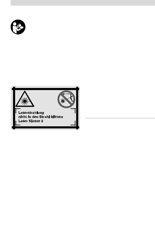
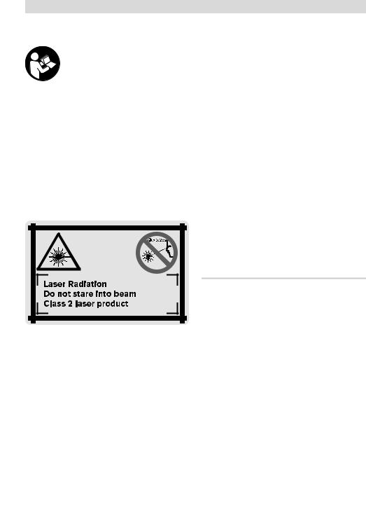
fDas Messwerkzeug wird mit einem Warnschild in deutscher Sprache ausgeliefert (in der Darstellung des Messwerkzeugs auf der Grafikseite mit Nummer 8 gekennzeichnet).
fVerwenden Sie die Laser-Sichtbrille nicht als Schutzbrille. Die Laser-Sichtbrille dient zum besseren Erkennen des Laserstrahls, sie schützt jedoch nicht vor der Laserstrahlung.
fVerwenden Sie die Laser-Sichtbrille nicht als Sonnenbrille oder im Straßenverkehr.
Die Laser-Sichtbrille bietet keinen vollständigen UV-Schutz und vermindert die Farbwahrnehmung.
fLassen Sie das Messwerkzeug von qualifiziertem Fachpersonal und nur mit OriginalErsatzteilen reparieren. Damit wird sichergestellt, dass die Sicherheit des Messwerkzeuges erhalten bleibt.
fLassen Sie Kinder das Laser-Messwerkzeug nicht unbeaufsichtigt benutzen. Sie könnten unbeabsichtigt Personen blenden.
IEC 60825-1:07 <1 mW, 635 nm
fRichten Sie den Laserstrahl nicht auf Personen oder Tiere und blicken Sie nicht selbst in den Laserstrahl. Dieses Messwerkzeug erzeugt Laserstrahlung der Laserklasse 2 gemäß IEC 60825-1. Dadurch können Sie Personen blenden.
Funktionsbeschreibung
Bitte klappen Sie die Ausklappseite mit der Darstellung des Messwerkzeugs auf, und lassen Sie diese Seite aufgeklappt, während Sie die Betriebsanleitung lesen.
Bestimmungsgemäßer Gebrauch
Das Messwerkzeug ist bestimmt zum Messen von Entfernungen, Längen, Höhen, Abständen und zum Berechnen von Flächen und Volumina. Das Messwerkzeug ist geeignet zum Messen von Aufmaßen im Innenund Außenbau.
2 609 140 582 | (29.7.08) |
Bosch Power Tools |

|
Deutsch | 7 |
|
|
Technische Daten |
|
|
|
Digitaler Laser-Entfernungsmesser |
DLE 40 |
|
Professional |
Sachnummer |
3 601 K16 300 |
Messbereich |
0,05–40 mA) |
Messgenauigkeit (typisch) |
±1,5 mmB) |
Kleinste Anzeigeneinheit |
1 mm |
Betriebstemperatur |
–10 °C...+50 °CC) |
Lagertemperatur |
–20 °C...+70 °C |
Relative Luftfeuchte max. |
90 % |
Laserklasse |
2 |
Lasertyp |
635 nm, <1 mW |
Durchmesser Laserstrahl (bei 25 °C) ca. |
|
– in 10 m Entfernung |
6 mm |
– in 40 m Entfernung |
24 mm |
Batterien |
4 x 1,5 V LR03 (AAA) |
Akkus |
4 x 1,2 V KR03 (AAA) |
Batterielebensdauer ca. |
30000D) |
– Einzelmessungen |
|
– Dauermessung |
5 hD) |
Abschaltautomatik nach ca. |
|
– Laser |
20 s |
– Messwerkzeug (ohne Messung) |
5 min |
Gewicht entsprechend EPTA-Procedure 01/2003 |
0,18 kg |
Maße |
58 x 100 x 32 mm |
Schutzart (außer Batteriefach) |
IP 54 (staubund spritzwassergeschützt) |
|
|
A)Die Reichweite wird größer, je besser das Laserlicht von der Oberfläche des Zieles zurückgeworfen wird (streuend, nicht spiegelnd) und je heller der Laserpunkt gegenüber der Umgebungshelligkeit ist (Innenräume, Dämmerung). Bei ungünstigen Bedingungen (z.B. Messen im Außenbereich mit starker Sonneneinstrahlung) kann es notwendig sein, die Zieltafel zu verwenden.
B)Bei ungünstigen Bedingungen wie z.B. starker Sonneneinstrahlung oder schlecht reflektierender Oberfläche beträgt die maximale Abweichung ±10 mm auf 40 m. Bei günstigen Bedingungen ist mit einem Einfluss von
±0,05 mm/m zu rechnen.
C)In der Funktion Dauermessung beträgt die max. Betriebstemperatur +40 °C.
D)Mit 1,2-V-Akkuzellen sind weniger Messungen möglich als mit 1,5-V-Batterien.
Bitte beachten Sie die Sachnummer auf dem Typenschild Ihres Messwerkzeugs, die Handelsbezeichnungen einzelner Messwerkzeuge können variieren.
Zur eindeutigen Identifizierung Ihres Messwerkzeugs dient die Seriennummer 17 auf dem Typenschild.
Bosch Power Tools |
2 609 140 582 | (29.7.08) |

8 | Deutsch
Abgebildete Komponenten
Die Nummerierung der abgebildeten Komponenten bezieht sich auf die Darstellung des Messwerkzeugs auf der Grafikseite.
1Taste Bezugsebene Vorderkante des Messwerkzeugs
2Speicherabruf-Taste „M=“
3Speicher-Additionstaste „M+“
4Taste für Flächenmessung
5Taste für Längenmessung
6Display
7Ausrichthilfe
8Laser-Warnschild
9Taste Messung und Dauermessung
10Taste für Volumenmessung
11Speicher-Subtraktionstaste „M–“
12Taste Bezugsebene Hinterkante des Messwerkzeugs
13Ein-Aus-Taste und Speicher-Löschtaste
141/4"-Gewinde
15Arretierung des Batteriefachdeckels
16Batteriefachdeckel
17Seriennummer
18Ausgang Laserstrahlung
19Empfangslinse
20Stativ*
21Laser-Sichtbrille*
22Laser-Zieltafel*
23Tragschlaufe*
24Schutztasche
*Abgebildetes oder beschriebenes Zubehör gehört nicht zum Standard-Lieferumfang.
Anzeigenelemente
aBatterie-Anzeige
bTemperaturanzeige
cMesswert/Ergebnis
dMaßeinheit
eBezugsebene der Messung
fLaser eingeschaltet
gEinzelmesswert
(bei Längenmessung: Ergebnis)
hMessfunktionen Längenmessung
Dauermessung
Flächenmessung
 Volumenmessung
i Speicherung von Messwerten
Montage
Batterien einsetzen/wechseln
Verwenden Sie ausschließlich Alkali-Mangan- Batterien oder Akkus.
Mit 1,2-V-Akkuzellen sind weniger Messungen möglich als mit 1,5-V-Batterien.
Zum Öffnen des Batteriefachdeckels 16 drücken Sie die Arretierung 15 in Pfeilrichtung und nehmen den Batteriefachdeckel ab. Setzen Sie die mitgelieferten Batterien ein. Achten Sie dabei auf die richtige Polung entsprechend der Darstellung im Batteriefach.
Erscheint das Batteriesymbol  erstmals im Display, dann sind noch mindestens 100 Messungen möglich. Wenn das Batteriesymbol blinkt, müssen Sie die Batterien auswechseln, Messungen sind nicht mehr möglich.
Ersetzen Sie immer alle Batterien gleichzeitig. Verwenden Sie nur Batterien eines Herstellers und mit gleicher Kapazität.
fNehmen Sie die Batterien aus dem Messwerkzeug, wenn Sie es längere Zeit nicht benutzen. Die Batterien können bei längerer Lagerung korrodieren und sich selbst entladen.
2 609 140 582 | (29.7.08) |
Bosch Power Tools |
Betrieb
Inbetriebnahme
fSchützen Sie das Messwerkzeug vor Nässe und direkter Sonneneinstrahlung.
fSetzen Sie das Messwerkzeug keinen extremen Temperaturen oder Temperaturschwankungen aus.
Ein-/Ausschalten
Zum Einschalten des Messwerkzeugs drücken Sie kurz auf die Ein-Aus-Taste 13 oder auf die Taste Messen 9. Beim Einschalten des Messwerkzeugs wird der Laserstrahl noch nicht eingeschaltet.
Zum Ausschalten des Messwerkzeugs drücken Sie lange auf die Ein-Aus-Taste 13.
Wird ca. 5 min lang keine Taste am Messwerkzeug gedrückt, dann schaltet sich das Messwerkzeug zur Schonung der Batterie automatisch ab.
Wurde ein Messwert gespeichert, bleibt er bei der automatischen Abschaltung erhalten. Nach dem Wiedereinschalten des Messwerkzeugs wird „M“ im Display angezeigt.
Messvorgang
Nach dem Einschalten befindet sich das Messwerkzeug in der Funktion Längenmessung. Andere Messfunktionen können Sie durch Drücken der jeweiligen Funktionstaste einstellen (siehe „Messfunktionen“, Seite 9).
Als Bezugsebene für die Messung ist nach dem Einschalten die Hinterkante des Messwerkzeugs ausgewählt. Zum Wechsel der Bezugsebene siehe „Bezugsebene wählen“, Seite 9.
Nach der Auswahl der Messfunktion und der Bezugsebene erfolgen alle weiteren Schritte durch Drücken der Taste Messen 9.
Legen Sie das Messwerkzeug mit der gewählten Bezugsebene an die gewünschte Messlinie (z.B. Wand) an.
Drücken Sie zum Einschalten des Laserstrahls kurz auf die Taste Messen 9.
Deutsch | 9
fRichten Sie den Laserstrahl nicht auf Personen oder Tiere und blicken Sie nicht selbst in den Laserstrahl, auch nicht aus größerer Entfernung.
Visieren Sie mit dem Laserstrahl die Zielfläche an. Drücken Sie zum Auslösen der Messung erneut kurz auf die Taste Messen 9.
In der Funktion Dauermessung beginnt die Messung sofort beim Einschalten der Funktion.
Der Messwert erscheint typischerweise innerhalb von 0,5 s und spätestens nach 4 s. Die Dauer der Messung hängt ab von der Entfernung, den Lichtverhältnissen und den Reflexionseigenschaften der Zielfläche. Das Ende der Messung wird durch einen Signalton angezeigt. Nach Beendigung der Messung wird der Laserstrahl automatisch abgeschaltet.
Erfolgt ca. 20 s nach dem Anvisieren keine Messung, schaltet sich der Laserstrahl zur Schonung der Batterien automatisch ab.
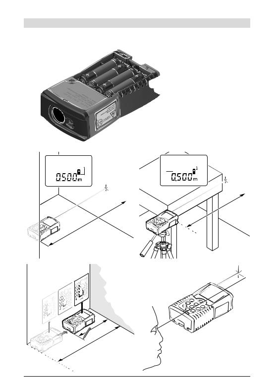
Bezugsebene wählen (siehe Bilder B–C)
Für die Messung können Sie unter zwei verschiedenen Bezugsebenen wählen:
–Drücken Sie die Taste 12 für Messungen ab der Hinterkante des Messwerkzeugs (z.B. beim Anlegen an Wände).
–Drücken Sie die Taste 1 für Messungen ab der Vorderkante des Messwerkzeugs (z.B. beim Messen ab einer Tischkante).
Die gewählte Bezugsebene wird im Display angezeigt. Nach jedem Einschalten des Messwerkzeugs ist die Hinterkante des Messwerkzeugs als Bezugsebene voreingestellt.
Messfunktionen
Längenmessung
Drücken Sie für Längenmessungen die Taste 5. Im Display erscheint die Anzeige für Längenmessung .
Drücken Sie zum Anvisieren und zum Messen je-
weils einmal kurz auf die
Taste Messen 9.
Der Messwert wird unten im Display angezeigt.
Bosch Power Tools |
2 609 140 582 | (29.7.08) |
10 | Deutsch
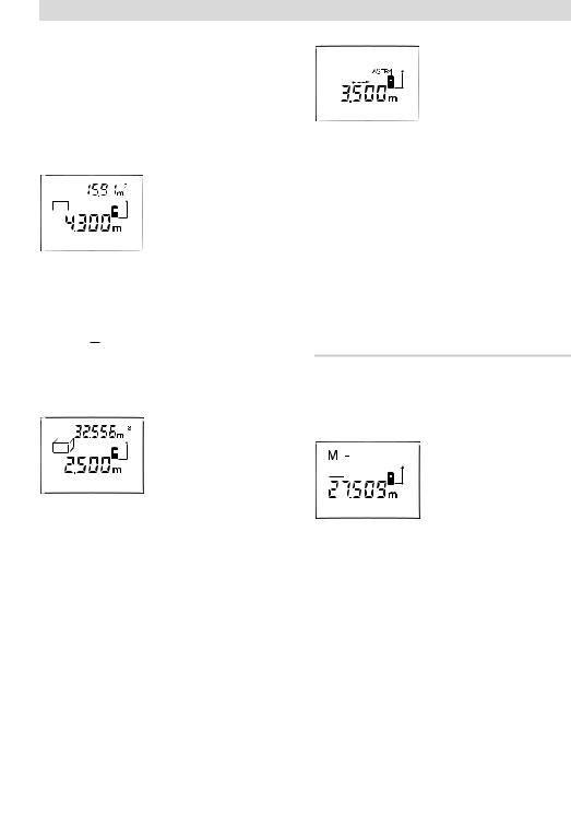
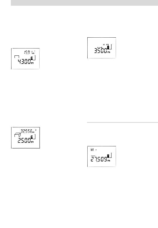
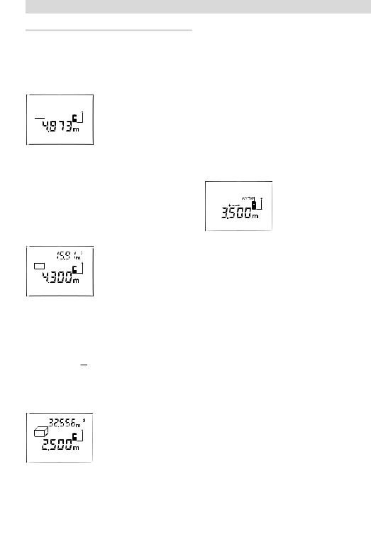
Flächenmessung
Drücken Sie für Flächenmessungen die Taste 4. Im Display erscheint die Anzeige für Flächenmessung  .
.
Messen Sie anschließend Länge und Breite nacheinander wie bei einer Längenmessung. Zwischen den beiden Messungen bleibt der Laserstrahl eingeschaltet.
Nach Abschluss der zweiten Messung wird die Fläche automatisch errechnet und angezeigt. Der letzte Einzelmesswert steht unten im Display, das Endergebnis oben.
Volumenmessung
Drücken Sie für Volumenmessungen die Taste 10. Im Display erscheint die Anzeige für Volumenmessung  .
.
Messen Sie anschließend Länge, Breite und Höhe nacheinander wie bei einer Längenmessung. Zwischen den drei Messungen bleibt der Laserstrahl eingeschaltet.
Nach Abschluss der dritten Messung wird das Volumen automatisch errechnet und angezeigt. Der letzte Einzelmesswert steht unten im Display, das Endergebnis oben.
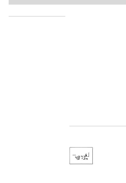
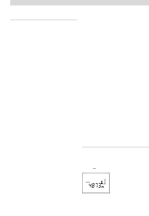
Dauermessung (siehe Bild D)
Die Dauermessung dient zum Abtragen von Maßen, z.B. aus Bauplänen. Bei der Dauermessung kann das Messwerkzeug relativ zum Ziel bewegt werden, wobei der Messwert ca. alle 0,5 s aktualisiert wird. Sie können sich z.B. von einer Wand bis zum gewünschten Abstand entfernen, die aktuelle Entfernung ist stets ablesbar.
Für Dauermessungen wählen Sie zuerst die Funktion Längenmessung und drücken dann die Taste 9 so lange, bis im Display die Anzeige 


für Dauermessung erscheint. Der Laser wird eingeschaltet und die Messung beginnt sofort.
Bewegen Sie das Messwerkzeug so lange, bis die gewünschte Entfernung unten im Display angezeigt wird.
Durch kurzes Drücken der Taste 9 beenden Sie die Dauermessung. Der letzte Messwert wird unten im Display angezeigt. Langes Drücken der Taste 9 startet die Dauermessung von Neuem.
Die Dauermessung schaltet nach 5 min automatisch ab. Der letzte Messwert bleibt im Display angezeigt.
Messwerte löschen
Durch kurzes Drücken der Taste 13 können Sie in allen Messfunktionen den zuletzt ermittelten Einzelmesswert löschen. Durch mehrmaliges kurzes Drücken der Taste werden die Einzelmesswerte in umgekehrter Reihenfolge gelöscht.
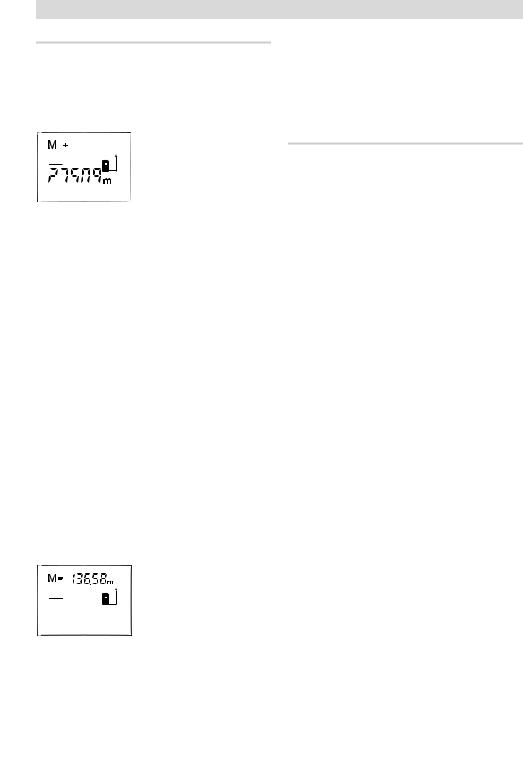
Speicherfunktionen
Beim Ausschalten des Messwerkzeugs bleibt der im Speicher befindliche Wert erhalten.
Messwerte speichern/addieren
Drücken Sie die SpeicherAdditionstaste 3, um den
aktuellen Messwert – je
nach der aktuellen Mess-
funktion ein Längen-, Flächenoder Volumenwert –
zu speichern. Sobald ein Wert gespeichert wurde, erscheint im Display „M“, das „+“ dahinter blinkt kurz.
Ist bereits ein Wert im Speicher vorhanden, so wird der neue Wert zum Speicherinhalt addiert, allerdings nur, wenn die Maßeinheiten übereinstimmen.
Befindet sich z.B. ein Flächenwert im Speicher, und der aktuelle Messwert ist ein Volumenwert, so kann die Addition nicht ausgeführt werden. Im Display blinkt kurz „Error“.
2 609 140 582 | (29.7.08) |
Bosch Power Tools |
Messwerte subtrahieren
Drücken Sie die Speicher-Subtraktionstaste 11, um den aktuellen Messwert vom Speicherwert abzuziehen. Sobald ein Wert subtrahiert wurde, erscheint im Display „M“, das „–“ dahinter blinkt kurz.
Ist bereits ein Wert gespeichert, dann kann der neue Messwert nur abgezogen werden, wenn die Maßeinheiten übereinstimmen (siehe „Messwerte speichern/addieren“).
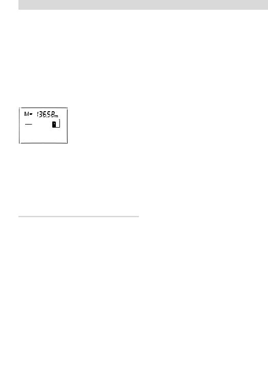
Speicherwert anzeigen
Drücken Sie die Speicher- abruf-Taste 2, um den im
Speicher befindlichen Wert anzuzeigen. Im Display erscheint „M=“. Wird der Speicherinhalt „M=“
im Display angezeigt, dann können Sie ihn durch Drücken der Speicher-Additionstaste 3 verdoppeln bzw. durch Drücken der Speicher-Sub- traktionstaste 11 auf Null setzen.
Speicher löschen
Zum Löschen des Speicherinhalts drücken Sie zuerst die Speicherabruf-Taste 2, sodass „M=“ im Display erscheint. Dann drücken Sie kurz auf die Taste 13; im Display wird kein „M“ mehr angezeigt.
Arbeitshinweise
Allgemeine Hinweise
Die Empfangslinse 19 und der Ausgang der Laserstrahlung 18 dürfen bei einer Messung nicht abgedeckt sein.
Das Messwerkzeug darf während einer Messung nicht bewegt werden (mit Ausnahme der Funktion Dauermessung). Legen Sie deshalb das Messwerkzeug möglichst an oder auf die Messpunkte.
Die Messung erfolgt am Mittelpunkt des Laserstrahls, auch bei schräg anvisierten Zielflächen.
Deutsch | 11
Einflüsse auf den Messbereich
Der Messbereich hängt von den Lichtverhältnissen und den Reflexionseigenschaften der Zielfläche ab. Verwenden Sie zur besseren Sichtbarkeit des Laserstrahls bei Arbeiten im Außenbereich und bei starker Sonneneinstrahlung die Laser-Sichtbrille 21 (Zubehör) und die Laser-Zieltafel 22 (Zubehör), oder schatten Sie die Zielfläche ab.
Einflüsse auf das Messergebnis
Aufgrund physikalischer Effekte kann nicht ausgeschlossen werden, dass es beim Messen auf verschiedenen Oberflächen zu Fehlmessungen kommt. Dazu zählen:
–transparente Oberflächen (z.B. Glas, Wasser),
–spiegelnde Oberflächen (z.B. poliertes Metall, Glas),
–poröse Oberflächen (z.B. Dämmmaterialien),
–strukturierte Oberflächen (z.B. Rauputz, Naturstein).
Verwenden Sie gegebenenfalls auf diesen Oberflächen die Laser-Zieltafel 22 (Zubehör).
Ebenso können Luftschichten mit unterschiedlichen Temperaturen oder indirekt empfangene Reflexionen den Messwert beeinflussen.
Anvisieren mit Ausrichthilfe (siehe Bild E)
Mittels der Ausrichthilfe 7 kann das Anvisieren über größere Entfernungen erleichtert werden. Schauen Sie dazu entlang der Ausrichthilfe an der Oberseite des Messwerkzeugs. Der Laserstrahl verläuft parallel zu dieser Sichtlinie.
Arbeiten mit dem Stativ (siehe Bild C)
Die Verwendung eines Stativs ist besonders bei größeren Entfernungen notwendig. Setzen Sie das Messwerkzeug mit dem 1/4"-Gewinde 14 auf die Schnellwechselplatte des Stativs 20 oder eines handelsüblichen Fotostativs auf. Schrauben Sie es mit der Feststellschraube der Schnellwechselplatte fest.
Beachten Sie bei der Positionierung des Stativs, dass die Messung je nach gewählter Bezugsebene ab Hinterbzw. Vorderkante des Messwerkzeugs erfolgt.
Bosch Power Tools |
2 609 140 582 | (29.7.08) |

12 | Deutsch
Fehler – Ursachen und Abhilfe
Ursache |
Abhilfe |
|
|
Temperaturanzeige (b) blinkt, Messung nicht möglich
Messwerkzeug ist außer- |
Abwarten, bis das |
halb der Betriebstempera- |
Messwerkzeug |
tur von –10 °C bis +50 °C |
Betriebstempe- |
(in der Funktion Dauer- |
ratur erreicht |
messung bis +40 °C). |
|
|
|
Batterie-Anzeige (a) erscheint |
|
|
|
Batteriespannung lässt |
Batterien |
nach (Messung noch |
wechseln |
möglich). |
|
Batterie-Anzeige (a) blinkt, Messung nicht möglich
Batteriespannung zu |
Batterien |
gering |
wechseln |
|
|
Anzeigen „Error“ und „––––“ im Display |
|
|
|
Winkel zwischen |
Winkel zwischen |
Laserstrahl und Ziel ist |
Laserstrahl und |
zu spitz. |
Ziel vergrößern |
|
|
Zielfläche reflektiert zu |
Laser-Zieltafel 22 |
stark (z.B. Spiegel) bzw. |
(Zubehör) ver- |
zu schwach (z.B. schwar- |
wenden |
zer Stoff), oder Umge- |
|
bungslicht ist zu stark. |
|
|
|
Ausgang Laserstrahlung |
Mit weichem Tuch |
18 bzw. Empfangslinse 19 |
Ausgang Laser- |
sind beschlagen (z.B. |
strahlung 18 bzw. |
durch schnellen Tempera- |
Empfangslinse 19 |
turwechsel). |
trockenreiben |
|
|
Berechneter Wert |
Berechnung in |
ist größer als |
Zwischenschritte |
99999 m/m2/m3. |
aufteilen |
Anzeige „Error“ blinkt oben im Display |
|
|
|
Addition/Subtraktion von |
Nur Messwerte mit |
Messwerten mit unter- |
gleichen Maßein- |
schiedlichen Maßeinheiten |
heiten addieren/ |
|
subtrahieren |
|
|
Ursache |
Abhilfe |
Messergebnis unzuverlässig |
|
|
|
Zielfläche reflektiert nicht |
Zielfläche |
eindeutig (z.B. Wasser, |
abdecken |
Glas). |
|
|
|
Ausgang Laserstrahlung |
Ausgang Laser- |
18 bzw. Empfangslinse 19 |
strahlung 18 bzw. |
ist verdeckt. |
Empfangslinse 19 |
|
freihalten |
Messergebnis unplausibel
Falsche Bezugsebene einBezugsebene pasgestellt send zur Messung
wählen
Hindernis im Verlauf des |
Laserpunkt muss |
Laserstrahls |
komplett auf Ziel- |
|
fläche liegen. |
|
|
Das Messwerkzeug überwacht die korrekte Funktion bei jeder Mes-
sung. Wird ein Defekt festgestellt, blinkt im Display nur noch das nebenstehende Symbol. In diesem
Fall, oder wenn die oben genannten Abhilfemaßnahmen einen Fehler nicht beseitigen können, führen Sie das Messwerkzeug über Ihren Händler dem Bosch-Kundendienst zu.
Genauigkeitsüberprüfung des Messwerkzeugs
Sie können die Genauigkeit des Messwerkzeugs wie folgt überprüfen:
–Wählen Sie eine auf Dauer unveränderliche Messstrecke von ca. 3 bis 10 m Länge, deren Länge Ihnen exakt bekannt ist (z.B. Raumbreite, Türöffnung). Die Messstrecke muss im Innenraum liegen, die Zielfläche der Messung glatt und gut reflektierend sein.
–Messen Sie die Strecke 10-mal hintereinander.
Der Messfehler darf maximal ±2,0 mm betragen. Protokollieren Sie die Messungen, um zu einem späteren Zeitpunkt die Genauigkeit vergleichen zu können.
2 609 140 582 | (29.7.08) |
Bosch Power Tools |

Wartung und Service
Wartung und Reinigung
Lagern und transportieren Sie das Messwerkzeug nur in der mitgelieferten Schutztasche.
Halten Sie das Messwerkzeug stets sauber.
Tauchen Sie das Messwerkzeug nicht ins Wasser oder andere Flüssigkeiten.
Wischen Sie Verschmutzungen mit einem feuchten, weichen Tuch ab. Verwenden Sie keine Reinigungsoder Lösemittel.
Pflegen Sie insbesondere die Empfangslinse 19 mit der gleichen Sorgfalt, mit der Brille oder Linse eines Fotoapparats behandelt werden müssen.
Sollte das Messwerkzeug trotz sorgfältiger Herstellungsund Prüfverfahren einmal ausfallen, ist die Reparatur von einer autorisierten Kundendienststelle für Bosch-Elektrowerkzeuge ausführen zu lassen.
Geben Sie bei allen Rückfragen und Ersatzteilbestellungen bitte unbedingt die 10-stellige Sachnummer laut Typenschild des Messwerkzeugs an.
Senden Sie im Reparaturfall das Messwerkzeug in der Schutztasche 24 ein.
Deutsch | 13
Kundendienst und Kundenberatung
Der Kundendienst beantwortet Ihre Fragen zu Reparatur und Wartung Ihres Produkts sowie zu Ersatzteilen. Explosionszeichnungen und Informationen zu Ersatzteilen finden Sie auch unter: www.bosch-pt.com
Das Bosch-Kundenberater-Team hilft Ihnen gerne bei Fragen zu Kauf, Anwendung und Einstellung von Produkten und Zubehören.
www.powertool-portal.de, das Internetportal für Handwerker und Heimwerker. www.ewbc.de, der Informations-Pool für Handwerk und Ausbildung.
Deutschland
Robert Bosch GmbH Servicezentrum Elektrowerkzeuge Zur Luhne 2
37589 Kalefeld – Willershausen
Tel. Kundendienst: +49 (1805) 70 74 10 Fax: +49 (1805) 70 74 11
E-Mail: Servicezentrum.Elektrowerkzeuge@de.bosch.com Tel. Kundenberatung: +49 (1803) 33 57 99
Fax: +49 (711) 7 58 19 30
E-Mail: kundenberatung.ew@de.bosch.com
Österreich
ABE Service GmbH Jochen-Rindt-Straße 1 1232 Wien
Tel. Service: +43 (01) 61 03 80 Fax: +43 (01) 61 03 84 91
Tel. Kundenberater: +43 (01) 7 97 22 30 66 E-Mail: abe@abe-service.co.at
Schweiz
Tel.: +41 (044) 8 47 15 11
Fax: +41 (044) 8 47 15 51
Luxemburg
Tel.: +32 (070) 22 55 65
Fax: +32 (070) 22 55 75
E-Mail: outillage.gereedschap@be.bosch.com
Bosch Power Tools |
2 609 140 582 | (29.7.08) |

14 | Deutsch
Entsorgung
Messwerkzeuge, Zubehör und Verpackungen sollen einer umweltgerechten Wiederverwertung zugeführt werden.
Nur für EU-Länder:
Werfen Sie Messwerkzeuge nicht in den Hausmüll!
Gemäß der Europäischen Richtlinie 2002/96/EG über Elektround
 Elektronik-Altgeräte und ihrer Umsetzung in nationales Recht müssen nicht mehr gebrauchsfähige Messwerkzeuge
getrennt gesammelt und einer umweltgerechten Wiederverwertung zugeführt werden.
Akkus/Batterien:
Werfen Sie Akkus/Batterien nicht in den Hausmüll, ins Feuer oder ins Wasser. Akkus/Batterien sollen gesammelt, recycelt oder auf umweltfreundliche Weise entsorgt werden.
Nur für EU-Länder:
Gemäß der Richtlinie 91/157/EWG müssen defekte oder verbrauchte Akkus/Batterien recycelt werden.
Nicht mehr gebrauchsfähige Akkus/Batterien können direkt abgegeben werden bei:
Deutschland
Recyclingzentrum Elektrowerkzeuge Osteroder Landstraße 3
37589 Kalefeld
Schweiz
Batrec AG
3752 Wimmis BE
Änderungen vorbehalten.
2 609 140 582 | (29.7.08) |
Bosch Power Tools |
Safety Notes
Working safely with the measuring tool is possible only when the operating and safety information are read completely and the instructions contained therein are strictly followed. Never make warning labels on the measuring tool unrecognisable.
SAVE THESE INSTRUCTIONS.
fCaution – The use of other operating or adjusting equipment or the application of other processing methods than those mentioned here, can lead to dangerous radiation exposure.
fThe measuring tool is delivered with a warning label in German language (marked with the number 8 in the representation of the measuring tool on the graphic page).
IEC 60825-1:07 <1 mW, 635 nm
fBefore putting into operation for the first time, attach the supplied sticker in your national language over the German text on the warning label.
fDo not direct the laser beam at persons or animals and do not stare into the laser beam yourself. This measuring tool produces laser class 2 laser radiation according to IEC 60825-1. This can lead to persons being blinded.
English | 15
fDo not use the laser viewing glasses as safety goggles. The laser viewing glasses are used for improved visualisation of the laser beam, but they do not protect against laser radiation.
fDo not use the laser viewing glasses as sun glasses or in traffic. The laser viewing glasses do not afford complete UV protection and reduce colour perception.
fHave the measuring tool repaired only through qualified specialists using original spare parts. This ensures that the safety of the measuring tool is maintained.
fDo not allow children to use the laser measuring tool without supervision. They could unintentionally blind other persons or themselves.
Functional Description
Please unfold the fold-out page with the representation of the measuring tool and leave it unfolded while reading the operating instructions.
Intended Use
The measuring tool is intended for measuring distances, lengths, heights, clearances and for calculating areas and volumes. The measuring tool is suitable for interior and exterior construction site measuring.
Bosch Power Tools |
2 609 140 582 | (29.7.08) |

16 | English
Technical Data
Digital Laser Rangefinder |
DLE 40 |
|
Professional |
Article number |
3 601 K16 300 |
Measuring range |
0.05–40 mA) |
Measuring accuracy (typically) |
±1.5 mmB) |
Lowest indication unit |
1 mm |
Operating temperature |
–10 °C...+50 °CC) |
Storage temperature |
–20 °C...+70 °C |
Relative air humidity, max. |
90 % |
Laser class |
2 |
Laser type |
635 nm, <1 mW |
Laser beam diameter (at 25 °C) approx. |
|
– at 10 m distance |
6 mm |
– at 40 m distance |
24 mm |
Batteries |
4 x 1.5 V LR03 (AAA) |
Rechargeable batteries |
4 x 1.2 V KR03 (AAA) |
Battery live, approximately |
30000D) |
– Individual measurements |
|
– Continuous measurement |
5 hD) |
Automatic switch-off after approx. |
|
– Laser |
20 s |
– Measuring tool (without measurement) |
5 min |
Weight according to EPTA-Procedure 01/2003 |
0.18 kg |
Dimensions |
58 x 100 x 32 mm |
Degree of protection |
IP 54 (dust and splash water protected) |
(excluding battery compartment) |
|
|
|
A)The working range increases depending on how well the laser light is reflected from the surface of the target (scattered, not reflective) and with increased brightness of the laser point to the ambient light intensity (interior spaces, twilight). In unfavourable conditions (e.g. when measuring outdoors at intense sunlight), it may be necessary to use the target plate.
B)In unfavourable conditions (e.g. at intense sunlight or an insufficiently reflecting surface), the maximum deviation is ±10 mm per 40 m. In favourable conditions, a deviation influence of ±0.05 mm/m must be taken into account.
C)In the continuous measurement function, the maximum operating temperature is +40 °C.
D)Fewer measurements are possible when using 1.2 V rechargeable batteries as compared with 1.5 V batteries.
Please observe the article number on the type plate of your measuring tool. The trade names of the individual measuring tools may vary.
The measuring tool can be clearly identified with the serial number 17 on the type plate.
2 609 140 582 | (29.7.08) |
Bosch Power Tools |

Product Features
The numbering of the product features shown refers to the illustration of the measuring tool on the graphic page.
1Button for reference level of the front measuring-tool edge
2Memory retrieve button “M=”
3Memory add button “M+”
4Area measurement button
5Length measurement button
6Display
7Alignment aid
8Laser warning label
9Button for measuring and continuous measuring
10Volume measurement button
11Memory subtraction button “M–”
12Button for reference level of the rear measuring-tool edge
13On/Off and memory delete button
141/4" thread
15Latch of battery lid
16Battery lid
17Serial number
18Laser beam outlet
19Reception lens
20Tripod*
21Laser viewing glasses*
22Laser target plate*
23Carrying strap*
24Protective case
*The accessories illustrated or described are not included as standard delivery.
English | 17
Display Elements
aBattery indication
bTemperature indicator
cMeasured value/result
dUnit of measure
eMeasurement reference level
fLaser switched on
gIndividual measured value (for length measurement: result)
hMeasuring functions
Length measurement
Tracking (continuous measurement) Area measurement
 Volume measurement i Measured values stored
Assembly
Inserting/Replacing the Battery
Use only alkali-manganese or rechargeable batteries.
Fewer measurements are possible when using 1.2 V rechargeable batteries as compared with 1.5 V batteries.
To open the battery lid 16, press the latch 15 in the direction of the arrow and remove the battery lid. Insert the batteries provided. Pay attention to the correct polarity of the batteries according to the representation in the battery compartment.
When the  battery symbol appears in the display for the first time, then at least 100 measurements are still possible. The batteries must be replaced when the battery symbol flashes; taking measurements is no longer possible.
Always replace all batteries at the same time. Only use batteries from one brand and with the identical capacity.
fRemove the batteries from the measuring tool when not using it for extended periods.
When storing for extended periods, the batteries can corrode and discharge themselves.
Bosch Power Tools |
2 609 140 582 | (29.7.08) |
18 | English
Operation
Initial Operation
fProtect the measuring tool against moisture and direct sun irradiation.
fDo not expose the measuring tool to extreme temperatures or variations in temperature.
Switching On and Off
To switch on the measuring tool, briefly press the On/Off button 13 or measuring button 9. When switching on the measuring tool, the laser beam is not switched on yet.
To switch off the measuring tool, press the On/Off button 13 for a few seconds.
If none of the measuring tool buttons are pressed for approx. 5 minutes, the measuring tool switches off automatically in order to extend the service life of the battery.
When a measured value has been stored, it is retained in automatic switch-off mode. When switching on the measuring tool again, “M” is indicated in the display.
Measuring Procedure
After switching on, the measuring tool is in the length measurement mode. Other measuring modes can be switched to by pressing the respective function/mode button (see “Measuring Functions”, page 18).
After switching on, the rear edge of the measuring tool is preset as the reference level for the measurement. To change the reference level, see “Selecting the Reference Level”, page 18.
Upon selection of the measuring function and the reference level, all further steps are carried out by pushing the measuring button 9.
With the reference level selected, place the measuring tool against the desired measuring line (e.g. a wall).
Briefly press the measuring button 9 to switch on the laser beam.
fDo not point the laser beam at persons or animals and do not look into the laser beam yourself, not even from a large distance.
Aim the laser beam at the target surface. Briefly press the measuring button 9 again to initate the measurement.
In the continuous measurement mode, the measurement begins immediately upon switching on the function.
Typically, the measured value appears after 0.5 and latest after 4 seconds. The duration of the measurement depends on the distance, the light conditions and the reflection properties of the target surface. The end of the measurement is indicated by a signal tone. The laser beam is switched off automatically upon completion of the measurement.
When no measurement has taken place approx. 20 seconds after sighting, the laser beam is switched off automatically to save the batteries.
Selecting the Reference Level (see figure B–C)
For the measurement, it is possible to select between two different reference levels:
–For measurements starting from the rear edge of the measuring tool (e.g., when placing against a wall), press button 12.
–For measurements starting from the front edge of the measuring tool (e.g., when measuring from onward from a table edge), press button 1.
The selected reference level is indicated on the display. Each time after switching on the measuring tool, the rear end of the measuring tool is preset as the reference level.
Measuring Functions
Length Measurement
For length measurement, push button 5. The indicator for length measurement appears in the display .
Press the measuring button 9 once for sighting and
once more to take the
measurement.
The measured value is indicated at the bottom in the display.
2 609 140 582 | (29.7.08) |
Bosch Power Tools |
Area Measurement
For area measurements, push button 4. The indicator for area measurement appears in the display  .
.
Afterwards, measure the length and the width, one after another, in the same manner as a length measurement. The laser beam remains switched on between both measurements.
After taking the second measurement, the area/ surface is automatically calculated and displayed. The last individual measured value is indicated at the bottom in the display, while the final result is shown at the top.
Volume Measurement
For volume measurements, push button 10. The indicator for volume measurement appears in the display  .
.
Afterwards, measure the length, width and the height, one after another, in the same manner as for a length measurement. The laser beam remains switched on between all three measurements.
After taking the third measurement, the volume is automatically calculated and displayed. The last individual measured value is indicated at the bottom in the display, while the final result is shown at the top.
Continuous Measurement (Tracking) (see figure D)
The continuous measurement function (tracking) is used for the transferring of measurements, e.g., from construction plans. In continuous measurement mode, the measuring tool can be moved relative to the target, whereby the measured value is updated approx. every
0.5 seconds. As an example, the user can move from a wall to the required distance, while the actual distance can be read continuously.
English | 19
For continuous measurements, first select the length measuring function and then press button 9 until the indicator for continuous measurement 

 appears on the display. The laser is switched on and the measurement starts immediately.
Move the measuring tool until the required distance
value is indicated in the
bottom of the display.
Briefly pressing button 9 ends the continuous measurement. The last meas-
ured value is indicated at the bottom in the display. Pressing button 9 for several seconds restarts a continuous measuring run.
The continuous measuring automatically switches off after 5 min. The last measured value remains indicated in the display.
Deleting Measured Values
Briefly pressing button 13 deletes the last individual measuring value determined in all measuring functions. Briefly pressing the button repeatedly deletes the individual measured values in reverse order.
Memory Functions
When switching off the measuring tool, the value in the memory is retained.
Storing/Adding Measured Values
Push the memory add button 3 in order to store the current measured value – a length, area or volume val-
ue, depending on the current measuring function.
As soon as a value has been stored, “M” is indicated in the display and the “+” behind it briefly flashes.
If a value is already stored in the memory, the new value is added to the memory contents, however, only when the measures of unit correspond.
As an example, when an area value is in the memory and the current measured value is a volume value, the addition cannot take place. “Error” briefly flashes in the display.
Bosch Power Tools |
2 609 140 582 | (29.7.08) |
20 | English
Subtracting Measured Values
Push the memory subtraction button 11 in order to subtract the current measured value from the memory value. As soon as a value has been subtracted, “M” is indicated in the display and the “–” behind it briefly flashes.
If a value is already stored in the memory, the new measured value can be subtracted only when the measures of unit correspond (see “Storing/Adding Measured Values”).
Displaying the Stored Value
Push the memory retrieve button 2 in order to display
the value stored in the memory. “M=” is indicated in the display. When the memory contents “M=” is
indicated in the display, it can be doubled by pushing the memory add button 3 or set to zero by pushing the memory subtract button 11.
Deleting the Memory
To delete the memory contents, first push the memory retrieve button 2, so that “M=” is indicated in the display. Then briefly press button 13; “M” is no longer indicated in the display.
Working Advice
General Information
The reception lens 19 and the laser beam outlet 18 must not be covered when taking a measurement.
The measuring tool must not be moved while taking a measurement (with the exception of the continuous measurement function). Therefore, place the measuring tool, as far as this is possible, against or on the measuring points.
Measurement takes place at the centre of the laser beam, even when target surfaces are sighted at an incline.
Influence Effects on the Measuring Range
The measuring range depends upon the light conditions and the reflection properties of the target surface. For improved visibility of the laser beam when working outdoors and when the sunlight is intense, use the laser viewing glasses 21 (accessory) and the laser target plate 22 (accessory), or shade off the target surface.
Influence Effects on the Measuring Result
Due to physical effects, faulty measurements cannot be excluded when measuring on different surfaces. Included here are:
–Transparent surfaces (e.g., glass, water),
–Reflecting surfaces (e.g., polished metal, glass),
–Porous surfaces (e.g. insulation materials),
–Structured surfaces (e.g., roughcast, natural stone).
If required, use the laser target plate 22 (accessory) on these surfaces.
Also, air layers with varying temperatures or indirectly received reflections can affect the measured value.
Sighting with the Alingment Aid (see figure E)
With the alignment aid 7, sighting over larger distances is a lot easier. For this, look alongside the aligning aid on the top side of the measuring tool. The laser beam runs parallel to this line of sight.
Working with the Tripod (see figure C)
The use of a tripod is particularly necessary for larger distances. Position the measuring tool with the 1/4" thread 14 onto the quick-change plate of the tripod 20 or a commercially available camera tripod. Tighten the measuring tool with the locking screw of the quick-change plate.
When positioning the tripod, observe that the measurement will take place beginning from the rear or front edge of the measuring tool, depending on the selected reference level.
2 609 140 582 | (29.7.08) |
Bosch Power Tools |
Troubleshooting – Causes and
Corrective Measures
Cause |
Corrective |
|
Measure |
|
|
Temperature indicator (b) flashes; measurement not possible
The measuring tool is |
Wait until the |
outside the operating |
measuring tool has |
temperature range from |
reached the oper- |
– 10 °C to + 50 °C (in the |
ating temperature |
function continuous |
|
measurement up to |
|
+40 °C). |
|
|
|
Battery indication (a) is indicated |
|
|
|
Battery voltage decreas- |
Replace batteries |
ing (measurement still |
|
possible) |
|
Battery indication (a) flashes, measurement not possible
Battery voltage too low |
Replace batteries |
|
|
“Error” and “––––” indication in display |
|
|
|
The angle between the |
Enlargen the angle |
laser beam and the target |
between the laser |
is too acute. |
beam and the |
|
target |
|
|
The target surface reflects |
Work with the |
too intensely (e.g. a mir- |
laser target plate |
ror) or insufficiently (e.g. |
22 (accessory) |
black fabric), or the ambi- |
|
ent light is too bright. |
|
|
|
The laser beam outlet 18 |
Wipe the laser |
or the reception lens 19 |
beam outlet 18 |
are misted up (e.g. due to |
and/or the recep- |
a rapid temperature |
tion lens 19 dry |
change). |
using a soft cloth |
|
|
Calculated value is great- |
Divide calculation |
er than 99999 m/m2/m3. |
into intermediate |
|
steps |
“Error” indication flashes at in display (top)
Addition/Subtraction of |
Only add/subtract |
measured values with dif- |
measured values |
ferent units of measure |
with the same |
|
units of measure |
|
|
|
English | 21 |
|
|
Cause |
Corrective |
|
Measure |
Unreliable measuring result |
|
|
|
The target surface does |
Cover off the |
not reflect correctly |
target surface |
(e.g. water, glass). |
|
|
|
The laser beam outlet 18 |
Make sure that the |
or the reception lens 19 |
laser beam outlet |
are covered. |
18 or the recep- |
|
tion lens 19 are un- |
|
obstructed |
Measuring result not plausible
Wrong reference level set Select reference level that corresponds to measurement
Obstruction in path of |
Laser point must |
laser beam |
be completely on |
|
target surface. |
|
|
The measuring tool monitors the correct function for each meas-
urement. When a defect is determined, only the symbol shown aside flashes in the display. In this
case, or when the above mentioned corrective measures cannot correct an error, have the measuring tool checked by an after-sales service agent for Bosch power tools.
Accuracy Check of the Measuring Tool
The accuracy of the measuring tool can be checked as follows:
–Select a permanently unchangeable measuring section with a length of approx. 3 to
10 metres; its length must be precisely known (e.g. the width of a room or a door opening). The measuring distance must be indoors; the target surface for the measurement must be smooth and reflect well.
–Measure the distance 10 times after another.
The measuring error must not amount to more than a maximum of ±2.0 mm. Keep a record of the measurements in order to compare the accuracy at a later time.
Bosch Power Tools |
2 609 140 582 | (29.7.08) |

22 | English
Maintenance and Service
Maintenance and Cleaning
Store and transport the measuring tool only in the supplied protective case.
Keep the measuring tool clean at all times.
Do not immerse the measuring tool into water or other fluids.
Wipe off debris using a moist and soft cloth. Do not use any cleaning agents or solvents.
Maintain the reception lens 19 in particular, with the same care as required for eye glasses or the lens of a camera.
If the measuring tool should fail despite the care taken in manufacturing and testing procedures, repair should be carried out by an authorized after-sales service centre for Bosch power tools.
In all correspondence and spare parts orders, please always include the 10-digit article number given on the type plate of the measuring tool.
In case of repairs, send in the measuring tool packed in its protective case 24.
After-sales Service and Customer Assistance
Our after-sales service responds to your questions concerning maintenance and repair of your product as well as spare parts. Exploded views and information on spare parts can also be found under:
www.bosch-pt.com
Our customer consultants answer your questions concerning best buy, application and adjustment of products and accessories.
Great Britain
Robert Bosch Ltd. (B.S.C.)
P.O. Box 98
Broadwater Park
North Orbital Road
Denham
Uxbridge
UB 9 5HJ
Tel. Service: +44 (0844) 736 0109
Fax: +44 (0844) 736 0146
E-Mail: SPT-Technical.de@de.bosch.com
Ireland
Origo Ltd.
Unit 23 Magna Drive
Magna Business Park
City West
Dublin 24
Tel. Service: +353 (01) 4 66 67 00
Fax: +353 (01) 4 66 68 88
Australia, New Zealand and Pacific Islands
Robert Bosch Australia Pty. Ltd. Power Tools
Locked Bag 66
Clayton South VIC 3169
Customer Contact Center Inside Australia:
Phone: +61 (01300) 307 044 Fax: +61 (01300) 307 045 Inside New Zealand:
Phone: +64 (0800) 543 353 Fax: +64 (0800) 428 570 Outside AU and NZ: Phone: +61 (03) 9541 5555 www.bosch.com.au
People’s Republic of China
Website: www.bosch-pt.com.cn
China Mainland
Bosch Power Tools (China) Co., Ltd. 567, Bin Kang Road
Bin Jiang District 310052 Hangzhou, P.R.China
Service Hotline: 800 8 20 84 84 Tel.: +86 (571) 87 77 43 38 Fax: +86 (571) 87 77 45 02
HK and Macau Special Administrative Regions
Robert Bosch Hong Kong Co. Ltd. 21st Floor, 625 King’s Road North Point, Hong Kong
Customer Service Hotline: +852 (21) 02 02 35 Fax: +852 (25) 90 97 62
E-Mail: info@hk.bosch.com www.bosch-pt.com.cn
2 609 140 582 | (29.7.08) |
Bosch Power Tools |

Indonesia
PT. Multi Tehaka
Kawasan Industri Pulogadung Jalan Rawa Gelam III No. 2 Jakarta 13930
Indonesia
Tel.: +62 (21) 4 60 12 28 Fax: +62 (21) 46 82 68 23
E-Mail: sales@multitehaka.co.id www.multitehaka.co.id
Phillippines
Robert Bosch, Inc.
Zuellig Building
Sen. Gil Puyat Avenue
Makati City 1200, Metro Manila
Philippines
Tel.: +63 (2) 8 17 32 31
www.bosch.com.ph
Malaysia
Robert Bosch (SEA.) Pte. Ltd. No. 8a, Jalan 13/6
46200 Petaling Jaya, Selangor,
Malaysia
Tel.: +6 (03) 7966 3000
Fax: +6 (03) 7958 3838
E-Mail: hengsiang.yu@my.bosch.com Toll Free Tel.: 1 800 880 188
Fax: +6 (03) 7958 3838 www.bosch.com.sg
Thailand
Robert Bosch Ltd. Liberty Square Building No. 287, 11 Floor Silom Road, Bangrak Bangkok 10500
Tel.: +66 (2) 6 31 18 79 – 18 88 (10 lines) Fax: +66 (2) 2 38 47 83
Robert Bosch Ltd., P. O. Box 2054 Bangkok 10501, Thailand
English | 23
Bosch Service – Training Centre 2869-2869/1 Soi Ban Kluay
Rama IV Road (near old Paknam Railway) Prakanong District
10110 Bangkok Thailand
Tel.: +66 (2) 6 71 78 00 – 4 Fax: +66 (2) 2 49 42 96 Fax: +66 (2) 2 49 52 99
Singapore
Robert Bosch (SEA.) Pte. Ltd. 38 C Jalan Pemimpin Singapore 915701
Republic of Singapore
Tel.: +65 (3) 50 54 94
Fax: +65 (3) 50 53 27 www.bosch.com.sg
Vietnam
Robert Bosch (SEA) Pte. Ltd – Vietnam
Representative Office
Saigon Trade Center, Suite 1206
37 Ton Duc Thang Street,
Ben Nghe Ward, District 1
HCMC
Vietnam
Tel.: +84 (8) 9111 374 – 9111 375
Fax: +84 (8) 9111376
Bosch Power Tools |
2 609 140 582 | (29.7.08) |

24 | English
Disposal
Measuring tools, accessories and packaging should be sorted for environmental-friendly recycling.
Only for EC countries:
Do not dispose of measuring tools into household waste!
According the European Guideline 2002/96/EC for Waste Electrical and Electronic Equipment and its
implementation into national right, measuring tools that are no longer usable must be collected separately and disposed of in an environmentally correct manner.
Battery packs/batteries:
Do not dispose of battery packs/batteries into household waste, fire or water. Battery packs/ batteries should be collected, recycled or disposed of in an environmental-friendly manner.
Only for EC countries:
Defective or dead out battery packs/batteries must be recycled according the guideline 91/157/EEC.
Batteries no longer suitable for use can be directly returned at:
Great Britain
Robert Bosch Ltd. (B.S.C.)
P.O. Box 98
Broadwater Park
North Orbital Road
Denham
Uxbridge
UB 9 5HJ
Tel. Service: +44 (0844) 736 0109
Fax: +44 (0844) 736 0146
E-Mail: SPT-Technical.de@de.bosch.com
Subject to change without notice.
2 609 140 582 | (29.7.08) |
Bosch Power Tools |

Consignes de sécurité
Lire toutes les instructions pour travailler avec l’appareil de mesure
sans risques et en toute sécurité.
S’assurer que les panneaux d’avertissement se trouvant sur l’appa-
reil de mesure sont toujours lisibles. GARDER PRECIEUSEMENT CES INSTRUCTIONS DE SECURITE.
fAttention – si d’autres dispositifs d’utilisation ou d’ajustage que ceux indiqués ici sont utilisés ou si d’autres procédés sont appliqués, ceci peut entraîner une exposition au rayonnement dangereuse.
fCet appareil de mesure est fourni avec une plaque d’avertissement en langue allemande (dans la représentation de l’appareil de mesure se trouvant sur la page des graphiques elle est marquée du numéro 8).
IEC 60825-1:07 <1 mW, 635 nm
fAvant la première mise en service, recouvrir le texte allemand de la plaque d’avertissement par l’autocollant fourni dans votre langue.
fNe pas diriger le faisceau laser vers des personnes ou des animaux et ne jamais regarder soi-même dans le faisceau laser. Cet appareil de mesure génère des rayonnements laser Classe laser 2 suivant IEC 60825-1. D’autres personnes peuvent être éblouies.
Français | 25
fNe pas utiliser les lunettes de vision du faisceau laser en tant que lunettes de protection. Les lunettes de vision du faisceau laser servent à mieux reconnaître le faisceau laser, elles ne protègent cependant pas du rayonnement laser.
fNe pas utiliser les lunettes de vision du faisceau laser en tant que lunettes de soleil ou en circulation routière. Les lunettes de vision du faisceau laser ne protègent pas parfaitement contre les rayons ultra-violets et réduisent la perception des couleurs.
fNe faire réparer l’appareil de mesure que par une personne qualifiée et seulement avec des pièces de rechange d’origine. Ceci permet d’assurer la sécurité de l’appareil de mesure.
fNe pas laisser les enfants utiliser l’appareil de mesure laser sans surveillance. Ils risqueraient d’éblouir par mégarde d’autres personnes.
Description du fonctionnement
Dépliez le volet sur lequel l’appareil de mesure est représenté de manière graphique. Laissez le volet déplié pendant la lecture de la présente notice d’utilisation.
Utilisation conforme
L’appareil de mesure est conçu pour mesurer les distances, les longueurs, les hauteurs et les écartements ainsi que pour calculer des surfaces et des volumes. L’appareil de mesure est approprié pour mesurer des métrés dans l’aménagement intérieur et extérieur.
Bosch Power Tools |
2 609 140 582 | (29.7.08) |

26 | Français
Caractéristiques techniques
Télémètre laser |
DLE 40 |
|
Professional |
N° d’article |
3 601 K16 300 |
|
|
Plage de mesure |
0,05–40 mA) |
Précision de mesure (typique) |
±1,5 mmB) |
Plus petite unité d’affichage |
1 mm |
|
|
Température de service |
–10 °C...+50 °CC) |
Température de stockage |
–20 °C...+70 °C |
|
|
Humidité relative de l’air max. |
90 % |
|
|
Classe laser |
2 |
|
|
Type de laser |
635 nm, <1 mW |
|
|
Diamètre du faisceau laser env. (à 25 °C) |
|
– à une distance de 10 m |
6 mm |
– à une distance de 40 m |
24 mm |
|
|
Piles |
4 x 1,5 V LR03 (AAA) |
Accus |
4 x 1,2 V KR03 (AAA) |
|
|
Durée de vie de la pile env. |
30000D) |
– Mesures individuelles |
|
– Mesure continue |
5 hD) |
Coupure automatique après env. |
|
– Laser |
20 s |
– Appareil de mesure (sans mesure) |
5 min |
|
|
Poids suivant EPTA-Procédure 01/2003 |
0,18 kg |
|
|
Dimensions |
58 x 100 x 32 mm |
Type de protection (à l’exception du compartiment à piles)
IP 54 (étanche à la poussière et aux projections d’eau)
A)L’étendue de la portée dépend de la qualité de la lumière laser réfléchie par la surface cible (dispersée, non pas miroitante) et du degré de clarté du point laser par rapport à la luminosité ambiante (locaux à l’intérieur, crépuscule). Dans des conditions défavorables (par ex. mesures effectuées à l’extérieur par un fort ensoleillement), il peut être nécessaire d’utiliser la platine de mesure.
B)Dans des conditions défavorables telles que fort ensoleillement ou surface mal réfléchissante, la divergence maximale est de ±10 mm pour 40 m. Dans des conditions favorables, il faut s’attendre à une influence de ±0,05 mm/m.
C)Dans le mode de mesure continu, la température de service maximale est de +40 °C.
D)Avec des accus 1,2 V moins de mesures sont possibles qu’avec des piles 1,5 V.
Faire attention au numéro d’article se trouvant sur la plaque signalétique de l’appareil de mesure. Les désignations commerciales des différents appareils peuvent varier.
Pour permettre une identification précise de votre appareil de mesure, le numéro de série 17 est marqué sur la plaque signalétique.
2 609 140 582 | (29.7.08) |
Bosch Power Tools |

Eléments de l’appareil
La numérotation des éléments de l’appareil se réfère à la représentation de l’appareil de mesure sur la page graphique.
1Touche niveau de référence bord avant de l’appareil de mesure
2Touche Appel des valeurs dans la mémoire
« M= »
3Touche Addition mémoire « M+ »
4Touche Mesure des surfaces
5Touche Mesure des longueurs
6Afficheur
7Trait de visée
8Plaque d’avertissement de laser
9Touche mesure et mesure continue
10Touche Mesure des volumes
11Touche Soustraction mémoire « M– »
12Touche niveau de référence bord arrière de l’appareil de mesure
13Touche Marche/Arrêt et touche remise à zéro de la mémoire
14Filetage 1/4"
15Blocage du couvercle du compartiment à piles
16Couvercle du compartiment à piles
17Numéro de série
18Sortie rayonnement laser
19Lentille de réception
20Trépied*
21Lunettes de vision du faisceau laser*
22Platine de mesure*
23Bretelle*
24Etui de protection
*Les accessoires décrits ou montrés ne sont pas compris dans l’emballage standard.
Français | 27
Eléments d’affichage
aIndicateur de charge de la pile
bAffichage de la température
cValeur de mesure/Résultat
dUnité de mesure
eNiveau de référence de la mesure
fLaser en fonctionnement
gValeur individuelle mesurée (pour la mesure des longueurs : résultat)
hFonctions de mesure
Mesure des longueurs Mesure continue
Mesure des surfaces
 Mesure des volumes
i Mémorisation des valeurs de mesure
Montage
Mise en place/changement des piles
N’utiliser que des piles ou accus alcalines au manganèse.
Avec des accus 1,2 V moins de mesures sont possibles qu’avec des piles 1,5 V.
Pour ouvrir le couvercle du compartiment à piles 16, appuyer sur le blocage 15 dans le sens de la flèche et enlever le couvercle du compartiment à piles. Introduire les piles fournies. Veiller à la bonne position des pôles qui doit correspondre à la figure se trouvant dans le compartiment à piles.
Quand le symbole de pile  apparaît pour la première fois à l’affichage, il est encore possible d’effectuer au moins 100 mesures. Dès que le symbole de pile clignote, il faut remplacer les piles, les mesures ne sont alors plus possibles.
Toujours remplacer toutes les piles en même temps. N’utiliser que des piles de la même marque avec la même capacité.
fSortir les piles de l’appareil de mesure au cas où l’appareil ne serait pas utilisé pour une période assez longue. En cas de stockage long, les piles peuvent corroder et se décharger.
Bosch Power Tools |
2 609 140 582 | (29.7.08) |

28 | Français
Fonctionnement
Mise en service
fProtéger l’appareil de mesure contre l’humidité, ne pas l’exposer aux rayons directs du soleil.
fNe pas exposer l’appareil de mesure à des températures extrêmes ou de forts changements de température.
Mise en Marche/Arrêt
Pour la mise en marche de l’appareil de mesure, appuyez brièvement sur l’interrupteur Marche/ Arrêt 13 ou sur la touche Mesurer 9. Lors de la mise en marche de l’appareil de mesure, le faisceau laser n’est pas encore mis en fonctionnement.
Pour arrêter l’appareil de mesure, appuyez longuement sur la touche Marche/Arrêt 13.
Si l’on n’appuie sur aucune touche sur l’appareil de mesure pendant env. 5 min, l’appareil s’arrête automatiquement afin de ménager la pile.
Si une valeur de mesure a été enregistrée, elle reste inchangée lors de l’arrêt automatique. Après la remise en service de l’appareil de mesure, « M » apparaît sur l’afficheur.
Mesure
Après avoir mis l’appareil de mesure en marche, celui-ci se trouve en mode de fonction « Mesure des longueurs ». Vous pouvez sélectionner d’autres fonctions de mesure en appuyant sur la touche de fonction respective (voir « Fonctions de mesure », page 29).
Après avoir mis l’appareil de mesure en marche, le bord arrière de l’appareil de mesure est le niveau de référence pour la mesure. Pour changer le niveau de référence, voir « Choisir le niveau de référence », page 28.
Après avoir sélectionné la fonction de mesure et le niveau de référence, tous le autres pas sont effectués en appuyant sur la touche Mesurer 9.
Positionner l’appareil de mesure avec le niveau de référence choisi sur le bord de mesure souhaité (par ex. le mur).
Pour mettre en fonctionnement le faisceau laser, appuyez brièvement sur la touche Mesurer 9.
fNe pas diriger le faisceau laser vers des personnes ou des animaux et ne jamais regarder dans le faisceau laser, même si vous êtes à grande distance de ce dernier.
Visez l’objectif avec le faisceau laser. Pour déclencher la mesure, appuyez de nouveau brièvement sur la touche Mesurer 9.
Dans le mode de mesure continu, la mesure commence immédiatement après avoir activé la fonction.
La valeur mesurée est typiquement affichée en 0,5 secondes, au plus tard au bout de 4 secondes. La durée de mesure dépend de la distance, des conditions de luminosité et des propriétés de réflexion de la surface cible. La fin de la mesure est indiquée par un signal acoustique. Une fois la mesure terminée, le faisceau laser est automatiquement éteint.
Après 20 secondes env. passées après la visée sans qu’une mesure n’ait été effectuée, le faisceau laser s’arrête automatiquement afin de ménager les piles.
Choisir le niveau de référence (voi figures B–C)
Il est possible de sélectionner deux différents niveaux de référence pour les mesures :
–Appuyez sur la touche 12 pour les mesures prises à partir du bord arrière de l’appareil de mesure (p.ex. lorsque l’appareil est positionné sur un mur).
–Appuyez sur la touche 1 pour les mesures prises à partir du bord avant de l’appareil de mesure (p.ex. pour les mesures prises à partir le bord d’une table).
Le niveau de référence choisi est affiché. Après chaque mise en service de l’appareil de mesure, le bord arrière de celui-ci est préréglé comme niveau de référence.
2 609 140 582 | (29.7.08) |
Bosch Power Tools |
Fonctions de mesure
Mesure des longueurs
Pour effectuer des mesures de longueur, appuyer sur la touche 5. L’affichage pour la mesure des longueurs  est affiché sur l’écran.
Pour la visée et la prise de mesure, appuyez une fois
brièvement sur la touche
Mesurer 9.
La valeur de mesure est affichée en bas sur l’afficheur.
Mesure des surfaces
Pour effectuer des mesures de surfaces, appuyer sur la touche 4. L’affichage pour la mesure des surfaces  est affiché sur l’écran.
Puis mesurer successivement la longueur et la largeur tout comme pour une mesure des longueurs. Le faisceau laser reste allumé entre les deux mesures.
Une fois la deuxième mesure terminée, la surface est automatiquement calculée et affichée. La dernière valeur individuelle mesurée apparaît en bas sur l’afficheur, le résultat final en haut.
Mesure des volumes
Pour effectuer des mesures de volumes, appuyer sur la touche 10. L’affichage pour la mesure des volumes  est affiché sur l’écran.
Puis mesurer successivement la longueur, la largeur et la hauteur tout comme pour une mesure des longueurs. Le faisceau laser reste allumé entre les trois mesures.
Une fois la troisième mesure terminée, le volume est automatiquement calculé et affiché. La dernière valeur individuelle mesurée apparaît en bas sur l’afficheur, le résultat final en haut.
Français | 29
Mesure continue (voir figure D)
La mesure continue sert à reporter des cotes, par ex. des plans de construction. Lors de la mesure continue, il est possible de déplacer l’appareil de mesure par rapport à la cible, la valeur de mesure étant actualisée toutes les 0,5 secondes env. L’utilisateur peut donc se déplacer par exemple d’un mur jusqu’à la distance souhaitée, la distance actuelle est toujours lisible sur l’afficheur.
Pour les mesures continues, choisissez d’abord la fonction mesure des longueurs et appuyez ensuite sur la touche 9 jusqu’à ce que l’affichage pour la mesure continue 

 apparaisse sur l’afficheur. Le laser est activé et la mesure commence immédiatement.
Déplacez l’appareil de mesure jusqu’à ce que la dis-
tance souhaitée soit affi-
chée en bas sur l’afficheur.
Pour terminer la mesure continue, appuyez brièvement sur la touche 9. La
dernière valeur de mesure est affichée en bas sur l’afficheur. Si l’on appuie longuement sur la touche 9, la mesure continue redémarre à nouveau.
La mesure continue s’arrête automatiquement au bout de 5 minutes. La dernière valeur de mesure reste affichée.
Effacement des valeurs de mesure
En appuyant brièvement sur la touche 13, il est possible d’effacer dans toutes les fonctions de mesure la dernière valeur individuelle déterminée. En appuyant plusieurs fois brièvement sur la touche, les valeurs individuelles déterminées sont effacées dans l’ordre inverse.
Bosch Power Tools |
2 609 140 582 | (29.7.08) |
30 | Français
Fonctions de mémoire
Lorsque l’appareil de mesure est mis hors fonction, la valeur se trouvant dans la mémoire est préservée.
Mémorisation/Addition des valeurs de mesure
Appuyer sur la touche Addition mémoire 3 pour mémoriser la valeur de mesure actuelle – une valeur de


 longueur, de surface ou de volume, suivant la fonction de mesure actuelle. Dès qu’une valeur a été mé-
morisée, « M » apparaît sur l’afficheur, le « + » derrière clignote pour une courte durée.
Au cas où une valeur se trouverait déjà dans la mémoire, la nouvelle valeur est additionnée à cette valeur dans la mémoire à condition que les unités de mesure coïncident.
Si, par ex., une valeur de surface se trouve dans la mémoire, et la valeur de mesure actuelle est une valeur de volume, l’addition ne peut pas être effectuée. « Error » clignote sur l’afficheur pour une courte durée.
Soustraction des valeurs de mesure
Appuyer sur la touche Soustraction mémoire 11 pour soustraire la valeur de mesure actuelle de la valeur mémorisée. Dès qu’une valeur a été soustraite, « M » apparaît sur l’afficheur, le « – » derrière clignote pour une courte durée.
Si une valeur est déjà mémorisée, la nouvelle valeur de mesure ne peut être soustraite que lorsque les unités de mesure coïncident (voir « Mémorisation/Addition des valeurs de mesure »).
Affichage de la valeur de la mémoire
Appuyer sur la touche Appel des valeurs dans la mé-
moire 2 pour afficher la valeur se trouvant dans la mémoire. « M= » apparaisse sur l’afficheur. Si la va-
leur « M= » dans la mémoire est affichée, il est possible de la doubler en appuyant sur la touche Addition mémoire 3 ou de la remettre à zéro en appuyant sur la touche Soustraction mémoire 11.
Effacer la mémoire
Pour effacer les valeurs dans la mémoire, appuyez d’abord sur la touche Appel des valeurs dans la mémoire 2 jusqu’à ce que « M= » apparaisse sur l’afficheur. Ensuite, appuyez brièvement sur la touche 13 ; « M » n’est plus indiqué sur l’afficheur.
Instructions d’utilisation
Indications générales
La lentille de réception 19 et la sortie du faisceau laser 18 ne doivent pas être couvertes lors d’une mesure.
L’appareil de mesure ne doit pas être bougé pendant une mesure (à l’exception de la fonction mesure continue). Positionner donc l’appareil de mesure si pi possible sur ou à côté des points de mesure.
La mesure s’effectue au centre du faisceau laser, même lorsque les surfaces cibles sont visées en biais.
Influences sur la plage de mesure
La plage de mesure dépend des conditions de luminosité et des propriétés de réflexion de la surface cible. Pour obtenir une meilleure visibilité du faisceau laser lors des travaux à l’extérieur et en cas d’un fort ensoleillement, utilisez les lunettes de vision du faisceau laser 21 (accessoire) et la platine de mesure 22 (accessoire) ou mettez à l’ombre la surface cible.
Influences sur le résultat de mesure
En raison de phénomènes physiques, il n’est pas exclu que les mesures effectuées sur des surfaces différentes donnent des résultats erronés. Ce sont par ex. :
–les surfaces transparentes (telles que verre, eau),
–les surfaces réfléchissantes (telles que métal, verre),
–les surfaces poreuses (par ex. matériaux solants),
–les surfaces à relief (par ex. crépi, pierre naturelle).
Le cas échéant, utilisez la platine de mesure 22 (accessoire) pour ces surfaces.
Des couches d’air à températures différentes ou les réfléchissements indirects peuvent également influencer la valeur de mesure.
2 609 140 582 | (29.7.08) |
Bosch Power Tools |
 Loading...