


Divar 700
Bosch Divar 700, Divar DHR754, Divar DHR753, Divar DHR751, Divar DHR732 Installation And Operation Manual
...
Divar 700 Series
Digital Hybrid HD Recorder / Digital Network HD Recorder
en Installation and Operation manual


Divar 700 Series Table of Contents | en 3
Bosch Security Systems Installation and Operation manual F.01U.246.471 | v3.4 | 2011.06
Table of Contents
1Safety 7
1.1 Safety precautions 7
1.2 Important safety instructions 7
1.3 Important Notices 9
1.4 FCC and UL 11
1.5 Bosch notices 12
2 Introduction 13
2.1 Digital video recorder for surveillance applications 13
2.1.1 Versions 13
2.1.2 Software 14
2.1.3 Firmware upgrades 14
2.1.4 Manuals 14
2.1.5 Features 14
2.1.6 On-screen help 15
2.2 Unpacking 15
2.2.1 Package contents 15
2.3 Installation environment 16
2.3.1 Mounting 16
2.3.2 Ventilation 16
2.3.3 Temperature 16
2.3.4 Power Supply 16
2.4 Associated equipment 16
3 Quick install 17
3.1 Connections 17
3.2 First-time use 18
3.3 Quick install menu 19
3.3.1 International 19
3.3.2 Schedule 20
3.3.3 Recording 21
3.3.4 Network 22
4 Hardware setup 23
4.1 Desktop installation 23
4.2 Rack mounting 23
4.3 Hard disk installation 24
4.3.1 Mounting instructions 24
4.4 Camera connections 26
4.5 Audio connections (hybrid version only) 27
4.6 Monitor connections 27
4.6.1 VGA 27
4.6.2 CVBS 28
4.6.3 Y/C 28
4.7 Monitor streaming connection (hybrid version) 28
4.8 RS232 COM port connections 29

4 en | Table of Contents Divar 700 Series
F.01U.246.471 | v3.4 | 2011.06 Installation and Operation manual Bosch Security Systems
4.9 Keyboard connections 30
4.10 Ethernet connection(s) 31
4.11 RS485 port 31
4.12 Biphase port 32
4.13 USB connectors 34
4.14 External alarm I/O connection 34
4.15 Malfunction relay 36
4.16 Power supply 37
4.17 Maintenance 37
5 Operating instructions 38
5.1 Front panel controls 38
5.1.1 Keys 38
5.1.2 Indicators 40
5.2 Mouse Controls 40
5.3 Viewing pictures 41
5.3.1 Monitor A 41
5.3.2 Monitor B (hybrid version only) 41
5.3.3 Viewing 41
5.4 Live and playback 43
5.4.1 Live mode 43
5.4.2 Accessing playback functions 43
5.4.3 Playback mode 43
5.5 Overview of the menu system 44
5.5.1 Access using the front panel keys 45
5.5.2 Access using the mouse 45
5.5.3 Access using the Intuikey keyboard 45
5.6 Search 46
5.6.1 Date/time search 46
5.6.2 Search 47
5.7 Export and local playback 51
5.7.1 Export 51
5.7.2 Playback 52
5.8 Configuration 53
5.8.1 Monitor settings 53
5.9 System information 57
5.9.1 Status 57
5.9.2 Logbook 60
5.10 Event handling 61
5.10.1 Alarms 61
5.10.2 Contact inputs 62
5.10.3 Motion events 62
5.10.4 Text events 62
5.10.5 Video loss alarm 62
6 Advanced configuration 63
6.1 International 64
6.1.1 Language 64
6.1.2 Time/date 65

Divar 700 Series Table of Contents | en 5
Bosch Security Systems Installation and Operation manual F.01U.246.471 | v3.4 | 2011.06
6.1.3 Time Server 66
6.2 Video & Audio 67
6.2.1 Analog Channels 67
6.2.2 IP Channels 68
6.2.3 Bitrates tab 71
6.3 Schedule 73
6.3.1 Setting the dynamic characteristics 73
6.3.2 Schedule 73
6.3.3 Exceptions 74
6.4 Recording 75
6.4.1 Normal 75
6.4.2 Contact 76
6.4.3 Text 76
6.4.4 Motion 76
6.4.5 Copy 77
6.5 Contacts 78
6.5.1 Contact inputs 78
6.5.2 Relay outputs 78
6.5.3 Contact input properties 78
6.6 Motion 80
6.6.1 Motion detection on analog cameras 80
6.6.2 Motion detection on IP cameras 81
6.7 Text data 83
6.7.1 Bridge 83
6.7.2 DirectIP 83
6.8 Event 85
6.8.1 General 85
6.8.2 Contact 86
6.8.3 Motion 86
6.8.4 Text 86
6.8.5 Video loss 87
6.8.6 Copy 87
6.9 Network 88
6.9.1 Setup - General 88
6.9.2 Setup - Connection 1 89
6.9.3 Setup - Connection 2 90
6.9.4 IP Range 91
6.9.5 Monitor Streaming 91
6.9.6 SNMP 93
6.10 Storage 95
6.10.1 Disk set 95
6.10.2 Disks 96
6.10.3 Service 97
6.10.4 Raid 4 protection 97
6.11 Users 99
6.11.1 General 99
6.11.2 Administrator 99
6.11.3 Users 1 - 7 100
6.12 System 102
6.12.1 Service 102

6 en | Table of Contents Divar 700 Series
F.01U.246.471 | v3.4 | 2011.06 Installation and Operation manual Bosch Security Systems
6.12.2 KBD 102
6.12.3 Serial ports 103
6.12.4 Licenses 104
6.12.5 Logging 104
7 Menu default values 105
7.1 Quick install menu defaults 105
7.2 Monitor view settings defaults 106
7.3 Configuration menu defaults 107
8 Technical specifications 113
8.1 Electrical 113
8.1.1 Mechanical 115
8.1.2 Environmental 115
8.1.3 Electromagnetic and Safety 116
8.1.4 Video bitrates (Kbps) for analog and IP SD cameras 116
8.1.5 Video bitrates (Kbps) for IP HD cameras 116
8.1.6 Accessories (Optional) 117
Divar 700 Series Safety | en 7
Bosch Security Systems Installation and Operation manual F.01U.246.471 | v3.4 | 2011.06
1Safety
1.1 Safety precautions
1.2 Important safety instructions
Read, follow, and retain for future reference all of the following safety instructions. Heed all
warnings on the unit and in the operating instructions before operating the unit.
1. Cleaning - Unplug the unit from the outlet before cleaning. Follow any instructions
provided with the unit. Generally, using a dry cloth for cleaning is sufficient but a moist,
fluff-free cloth or leather shammy may also be used. Do not use liquid cleaners or aerosol
cleaners.
2. Heat Sources - Do not install the unit near any heat sources such as radiators, heaters,
stoves, or other equipment (including amplifiers) that produce heat.
3. Ventilation - Any openings in the unit enclosure are provided for ventilation to prevent
overheating and ensure reliable operation. Do not block or cover these openings. Do not
place the unit in an enclosure unless proper ventilation is provided, or the manufacturer's
instructions have been adhered to.
4. Water - Do not use this unit near water, for example near a bathtub, washbowl, sink,
laundry basket, in a damp or wet basement, near a swimming pool, in an outdoor
installation, or in any area classified as a wet location. To reduce the risk of fire or
electrical shock, do not expose this unit to rain or moisture.
5. Object and liquid entry - Never push objects of any kind into this unit through openings
as they may touch dangerous voltage points or short-out parts that could result in a fire
or electrical shock. Never spill liquid of any kind on the unit. Do not place objects filled
with liquids, such as vases or cups, on the unit.
6. Lightning - For added protection during a lightning storm, or when leaving this unit
unattended and unused for long periods, unplug the unit from the wall outlet and
disconnect the cable system. This will prevent damage to the unit from lightning and
power line surges.
7. Controls adjustment - Adjust only those controls specified in the operating instructions.
Improper adjustment of other controls may cause damage to the unit. Use of controls or
adjustments, or performance of procedures other than those specified, may result in
hazardous radiation exposure.
8. Overloading - Do not overload outlets and extension cords. This can cause fire or
electrical shock.
DANGER!
High risk: This symbol indicates an imminently hazardous situation such as "Dangerous
Voltage" inside the product.
If not avoided, this will result in an electrical shock, serious bodily injury, or death.
WARNING!
Medium risk: Indicates a potentially hazardous situation.
If not avoided, this could result in minor or moderate bodily injury.
CAUTION!
Low risk: Indicates a potentially hazardous situation.
if not avoided, this could result in property damage or risk of damage to the unit.

8 en | Safety Divar 700 Series
F.01U.246.471 | v3.4 | 2011.06 Installation and Operation manual Bosch Security Systems
9. Power supply cord and plug protection - Protect the power supply cord and plug from
foot traffic, being pinched by items placed upon or against them at electrical outlets, and
its exit from the unit. For units intended to operate with 230 VAC, 50 Hz, the power
supply cord must comply with the latest versions of IEC 60227. For units intended to
operate with 120 VAC, 60 Hz, the power supply cord must comply with the latest
versions of UL 62 and CSA 22.2 No.49.
10. Power disconnect - Units have power supplied to the unit whenever the power cord is
inserted into the power source. The power cord plug is the main power disconnect
device for switching off the voltage for the unit.
11. Power sources - Operate the unit only from the type of power source indicated on the
label. Before proceeding, be sure to disconnect the power from the cable to be installed
into the unit.
12. Servicing - Do not attempt to service this unit yourself. Opening or removing covers may
expose you to dangerous voltage or other hazards. Refer all servicing to qualified service
personnel.
13. Damage requiring service - Unplug the unit from the main AC power source and refer
servicing to qualified service personnel when any damage to the equipment has
occurred, such as:
– the power supply cord or plug is damaged;
– exposure to moisture, water, and/or inclement weather (rain, snow, etc.);
– liquid has been spilled in or on the equipment;
– an object has fallen into the unit;
– unit has been dropped or the unit cabinet is damaged;
– unit exhibits a distinct change in performance;
– unit does not operate normally when the user correctly follows the operating
instructions.
14. Replacement parts - Be sure the service technician uses replacement parts specified by
the manufacturer, or that have the same characteristics as the original parts.
Unauthorized substitutions could void the warranty and cause fire, electrical shock, or
other hazards.
15. Safety check - Safety checks should be performed upon completion of service or repairs
to the unit to ensure proper operating condition.
16. Installation - Install in accordance with the manufacturer's instructions and in
accordance with applicable local codes.
17. Attachments, changes or modifications - Only use attachments/accessories specified by
the manufacturer. Any change or modification of the equipment, not expressly approved
by Bosch, could void the warranty or, in the case of an authorization agreement, authority
to operate the equipment.
Divar 700 Series Safety | en 9
Bosch Security Systems Installation and Operation manual F.01U.246.471 | v3.4 | 2011.06
1.3 Important Notices
All-pole power switch - Incorporate an all-pole power switch, with a contact separation of at
least 3 mm in each pole, into the electrical installation of the building.If it is needed to open
the housing for servicing and/or other activities, use this all-pole switch as the main
disconnect device for switching off the voltage to the unit.
Battery replacement - For qualified service personnel only - A lithium battery is located
inside the unit enclosure. To avoid danger of explosion, replace the battery as per
instructions. Replace only with the same or equivalent type recommended by the
manufacturer. Dispose of the replaced battery in an environmentally friendly way and not with
other solid waste. Refer all servicing to qualified service personnel.
Coax grounding:
– Ground the cable system if connecting an outside cable system to the unit.
– Connect outdoor equipment to the unit's inputs only after this unit has had its grounding
plug connected to a grounded outlet or its ground terminal is properly connected to a
ground source.
– Disconnect the unit's input connectors from outdoor equipment before disconnecting
the grounding plug or grounding terminal.
– Follow proper safety precautions such as grounding for any outdoor device connected to
this unit.
U.S.A. models only - Section 810 of the National Electrical Code, ANSI/NFPA No.70, provides
information regarding proper grounding of the mount and supporting structure, grounding of
the coax to a discharge unit, size of grounding conductors, location of discharge unit,
connection to grounding electrodes, and requirements for the grounding electrode.
Environmental statement - Bosch has a strong commitment towards the environment. This
unit has been designed to respect the environment as much as possible.
Electrostatic-sensitive device - Use proper CMOS/MOS-FET handling precautions to avoid
electrostatic discharge.
Accessories - Do not place this unit on an unstable stand, tripod, bracket, or mount. The unit
may fall, causing serious injury and/or serious damage to the unit. Use only with the cart,
stand, tripod, bracket, or table specified by the manufacturer. When a cart is used, use
caution and care when moving the cart/apparatus combination to avoid injury from tip-over.
Quick stops, excessive force, or uneven surfaces may cause the cart/unit combination to
overturn. Mount the unit per the manufacturer's instructions.
CAUTION!
Class I Laser Product
Invisible laser radiation when open. Avoid exposure to beam.
CAUTION!
This device is intended for the use in public areas only.
U.S. federal law strictly prohibits surreptitious recording of oral communications.
Disposal - Your Bosch product was developed and manufactured with high-quality material
and components that can be recycled and reused. This symbol means that electronic and
electrical appliances, which have reached the end of their working life, must be collected and
disposed of separately from household waste material. Separate collecting systems are
usually in place for disused electronic and electrical products. Please dispose of these units
at an environmentally compatible recycling facility, per European Directive 2002/96/EC.

10 en | Safety Divar 700 Series
F.01U.246.471 | v3.4 | 2011.06 Installation and Operation manual Bosch Security Systems
NOTE: Wear required grounded wrist straps and observe proper ESD safety precautions when
handling the electrostatic-sensitive printed circuit boards.
Fuse rating - For protection of the device, the branch circuit protection must be secured with
a maximum fuse rating of 16A. This must be in accordance with NEC800 (CEC Section 60).
Grounding and polarization - This unit may be equipped with a polarized alternating current
line plug (a plug with one blade wider than the other blade). This safety feature allows the
plug to fit into the power outlet in only one way. If unable to insert the plug fully into the
outlet, contact a locally certified electrician to replace the obsolete outlet. Do not defeat the
safety purpose of the polarized plug.
Alternately, this unit may be equipped with a 3-pole grounding plug (a plug with a third pin for
earth grounding). This safety feature allows the plug to fit into a grounded power outlet only.
If unable to insert the plug into the outlet, contact a locally certified electrician to replace the
obsolete outlet. Do not defeat the safety purpose of the grounding plug.
Moving - Disconnect the power before moving the unit. Move the unit with care. Excessive
force or shock may damage the unit and the hard disk drives.
Outdoor signals - The installation for outdoor signals, especially regarding clearance from
power and lightning conductors and transient protection, must be in accordance with NEC725
and NEC800 (CEC Rule 16-224 and CEC Section 60).
Permanently connected equipment - Incorporate a readily accessible disconnect device
external to the equipment.
Pluggable equipment - Install the socket outlet near the equipment so it is easily accessible.
Power resupply - If the unit is forced to power down due to exceeding the specified operating
temperatures, disconnect the power cord, wait for at least 30 seconds, and then reconnect
the power cord.
Rack-mount:
– Elevated Operating Ambient - If installed in a closed or multi-unit rack assembly, the
operating ambient temperature of the rack environment may be greater than room
ambient. Therefore, consideration should be given to installing the equipment in an
environment compatible with the maximum ambient temperature (Tma) specified by the
manufacturer.
– Reduced Air Flow - Installation of the equipment in a rack should be such that the amount
of air flow required for safe operation of the equipment is not compromised.
– Mechanical loading - Mounting of the equipment in the rack should be such that a
hazardous condition is not achieved due to uneven mechanical loading.
– Circuit Overloading - Consideration should be given to the connection of the equipment
to the supply circuit and the effect that overloading of the circuits might have on
overcurrent protection and supply wiring. Appropriate consideration of equipment
nameplate ratings should be used when addressing this concern.
– Reliable Earthing - Reliable earthing of rack-mounted equipment should be maintained.
Particular attention should be given to supply connections other than direct connections
to the branch circuit (e.g. use of power strips).
For detailed instructions, please refer to Section 4.2 Rack mounting.
SELV - All the input/output ports are Safety Extra Low Voltage (SELV) circuits. SELV circuits
should only be connected to other SELV circuits.
Video loss - Video loss is inherent to digital video recording; therefore, Bosch Security
Systems cannot be held liable for any damage that results from missing video information. To
minimize the risk of lost digital information, Bosch Security Systems recommends multiple,
redundant recording systems, and a procedure to back up all analog and digital information.

Divar 700 Series Safety | en 11
Bosch Security Systems Installation and Operation manual F.01U.246.471 | v3.4 | 2011.06
1.4 FCC and UL
FCC & ICES Information
(U.S.A. and Canadian Models Only)
This equipment has been tested and found to comply with the limits for a Class B digital
device, pursuant to part 15 of the FCC Rules. These limits are designed to provide reasonable
protection against harmful interference in a residential installation. This equipment
generates, uses, and can radiate radio frequency energy and, if not installed and used in
accordance with the instructions, may cause harmful interference to radio communications.
However, there is no guarantee that interference will not occur in a particular installation. If
this equipment does cause harmful interference to radio or television reception, which can be
determined by turning the equipment off and on, the user is encouraged to try to correct the
interference by one or more of the following measures:
– reorient or relocate the receiving antenna;
– increase the separation between the equipment and receiver;
– connect the equipment into an outlet on a circuit different from that to which the
receiver is connected;
– consult the dealer or an experienced radio/TV technician for help.
Intentional or unintentional modifications, not expressly approved by the party responsible
for compliance, shall not be made. Any such modifications could void the user's authority to
operate the equipment. If necessary, the user should consult the dealer or an experienced
radio/television technician for corrective action.
The user may find the following booklet, prepared by the Federal Communications
Commission, helpful: How to Identify and Resolve Radio-TV Interference Problems. This booklet
is available from the U.S. Government Printing Office, Washington, DC 20402, Stock No. 004000-00345-4.
INFORMATIONS FCC ET ICES
(modèles utilisés aux États-Unis et au Canada uniquement)
Suite à différents tests, cet appareil s'est révélé conforme aux exigences imposées aux
appareils numériques de classe B, en vertu de la section 15 du règlement de la Commission
fédérale des communications des États-Unis (FCC), et en vertu de la norme ICES-003 d'Industrie
Canada. Ces exigences visent à fournir une protection raisonnable contre les interférences
nuisibles lorsque l'appareil est utilisé dans le cadre d'une installation résidentielle. Cet
appareil génère, utilise et émet de l'énergie de radiofréquences et peut, en cas d'installation
ou d'utilisation non conforme aux instructions, engendrer des interférences nuisibles au
niveau des radiocommunications. Toutefois, rien ne garantit l'absence d'interférences dans
une installation particulière. Il est possible de déterminer la production d'interférences en
mettant l'appareil successivement hors et sous tension, tout en contrôlant la réception radio
ou télévision. L'utilisateur peut parvenir à éliminer les interférences éventuelles en prenant
une ou plusieurs des mesures suivantes:
– Modifier l'orientation ou l'emplacement de l'antenne réceptrice;
– Éloigner l'appareil du récepteur;
– Brancher l'appareil sur une prise située sur un circuit différent de celui du récepteur;
– Consulter le revendeur ou un technicien qualifié en radio/télévision pour obtenir de
l'aide.
Toute modification apportée au produit, non expressément approuvée par la partie
responsable de l'appareil, est strictement interdite. Une telle modification est susceptible
d'entraîner la révocation du droit d'utilisation de l'appareil.
La brochure suivante, publiée par la Commission fédérale des communications (FCC), peut
s'avérer utile : How to Identify and Resolve Radio-TV Interference Problems (Comment identifier

12 en | Safety Divar 700 Series
F.01U.246.471 | v3.4 | 2011.06 Installation and Operation manual Bosch Security Systems
et résoudre les problèmes d’interférences de radio et de télévision). Cette brochure est
disponible auprès du U.S. Government Printing Office, Washington, DC 20402, États-Unis,
sous la référence n° 004-000-00345-4.
Disclaimer
Underwriter Laboratories Inc. ("UL") has not tested the performance or reliability of the
security or signaling aspects of this product. UL has only tested fire, shock and/or casualty
hazards as outlined in UL's Standard(s) for Safety for Information Technology Equipment, UL
60950-1. UL Certification does not cover the performance or reliability of the security or
signaling aspects of this product.
UL MAKES NO REPRESENTATIONS, WARRANTIES, OR CERTIFICATIONS WHATSOEVER
REGARDING THE PERFORMANCE OR RELIABILITY OF ANY SECURITY OR SIGNALINGRELATED FUNCTIONS OF THIS PRODUCT.
1.5 Bosch notices
Copyright
This manual is the intellectual property of Bosch Security Systems and is protected by
copyright.
All rights reserved.
Trademarks
All hardware and software product names used in this document are likely to be registered
trademarks and must be treated accordingly.
NOTE:
This manual has been compiled with great care and the information it contains has been
thoroughly verified. The text was complete and correct at the time of printing. The ongoing
development of the products may mean that the content of the user guide can change without
notice. Bosch Security Systems accepts no liability for damage resulting directly or indirectly
from faults, incompleteness or discrepancies between the user guide and the product
described.
More information
For more information please contact the Bosch Security Systems location nearest you or visit
www.boschsecurity.com

Divar 700 Series Introduction | en 13
Bosch Security Systems Installation and Operation manual F.01U.246.471 | v3.4 | 2011.06
2 Introduction
2.1 Digital video recorder for surveillance applications
The Divar 700 Series is a video recording system that records multiple camera signals while
simultaneously providing live multiscreen viewing and playback.
The unit has comprehensive search and playback facilities for viewing stored video. Once
configured, all recording takes place in the background without requiring operator
intervention. For analog and SD IP cameras the maximum recording rates of 30 (NTSC) and 25
(PAL) images per second, per channel, are guaranteed. For HD IP cameras recording rates of
up to 60 images per second, per channel (720p60), are supported. The recording rate and
quality are selectable per camera. Up to four internal hard disks can be used to provide
various storage capacities for recording.
All models have extensive alarm handling functions and telemetry control. Alarm functions
include motion detection in user-definable areas of the image on any camera input.
The unit can be easily operated and programmed via the on-screen display menu system using
the front panel control keys or the mouse. Connect a KBD (Intuikey) keyboard for PTZ control
and to improve the ease-of-use. Full-screen, quad and multiscreen viewing is available. VGA,
CVBS and Y/C video outputs in either NTSC or PAL are provided.
2.1.1 Versions
There are various Divar 700 Series models available:
The optional IP channels are activated with a license.
Each of these models is available with storage capacities of either 500 GB, 2 TB, 4 TB or 8 TB.
Models with 4 TB and 8 TB have four hard disks. These models can be operated in RAID-4
mode with the optional RAID-4 license. This protects against single disk failures.
Model
number
Analog A/V
inputs
Monitor
outputs
Dual mono
outputs
IP channels DVD
writer
Network
ports
DHR754 16 2 2 0 (+16
optional)
Yes 2
DHR753 16 2 2 0 (+16
optional)
Yes 1
DHR751 16 2 2 0 (+16
optional)
No 1
DHR732 8 2 2 0 (+8
optional)
Yes 1
DHR730 8 2 2 0 (+8
optional)
No 1
DNR754 0 1 1 16 (+16
optional)
Yes 2
DNR753 0 1 1 16 (+16
optional)
Yes 1
DNR732 0 1 1 8 (+8
optional)
Yes 1

14 en | Introduction Divar 700 Series
F.01U.246.471 | v3.4 | 2011.06 Installation and Operation manual Bosch Security Systems
Hybrid verions (DHR)
The DHR hybrid versions have looping auto-terminating analog video inputs and outputs, and
audio inputs and outputs. Two VGA connectors provide outputs for an A and a B monitor.
Monitor A displays full-screen or multiscreen digital pictures that can be frozen and zoomed.
Monitor B displays live full-screen or multiscreen pictures. Both 8-channel and 16-channel
versions operate in exactly the same way except that fewer camera, audio, and alarm inputs
are present, and the number of available multiscreen views differs.
Network verions (DNR)
The DNR network versions have single VGA, CVBS and Y/C video output connectors for an A
monitor. Monitor A displays full-screen or multiscreen digital pictures that can be frozen and
zoomed.
2.1.2 Software
The BVC application is used via the network for live viewing and playback. The Configuration
Manager application detects IP devices and configures BVIP devices. The Divar 700
Configuration Tool is used to configure the Divar 700 recorders on the network.
Seven simultaneous users can control multiple units. Authenticity checks for both local and
remote playback are available. A dedicated PC player is provided for the authenticated
playback of archived video files. The PC-based Configuration Tool facilitates the installation of
the unit.
An SDK (software development kit) is available to integrate the unit into third party
management software.
2.1.3 Firmware upgrades
Firmware upgrades are released periodically. Check the Bosch Security website for the latest
version.
Note:
Whenever the Divar 700 is upgraded to a newer software version, any saved configuration
backup file exported from the older version of the software will no longer be useable with the
new software. During the upgrade process, the existing configuration of the Divar 700 will be
adapted to the new version of the software. Re-export the configuration to a new backup file
to ensure that a backup configuration file can be restored using the new software.
2.1.4 Manuals
Two printed manuals are supplied:
– Quick Installation guide - gives a brief overview on how to set up and install the product.
– Installation and Operation manual (this manual) - a detailed description of how to install
and operate the product.
Three additional manuals in PDF format are supplied on the CD-ROM:
– Configuration Tool operation manual - a detailed description for administrators on how to
use the Configuration Tool to set up the Divar 700 Series.
– Bosch Video Client operation manual - a detailed description for end-users and
administrators on how to set up and operate the Bosch Video Client software.
– Archive Player operation manual - a detailed description for end-users and administrators
on how to set up and operate the Archive Player software.
2.1.5 Features
The Divar 700 Series has the following features:
– 8 or 16 looped-through, auto-terminating camera inputs (hybrid versions)
– 8 or 16 audio inputs (hybrid versions)
– Two dual mono audio outputs (hybrid versions)

Divar 700 Series Introduction | en 15
Bosch Security Systems Installation and Operation manual F.01U.246.471 | v3.4 | 2011.06
– Dual monitor outputs (hybrid versions)
– Full-screen and various multiscreen display capabilities in live and playback modes
– Spot monitor output with sequencing, multiscreen, and OSD (hybrid versions)
– Optional support for up to 8 (or 16) SD or HD IP cameras on hybrid versions
– Up to 32 SD or HD IP cameras on network versions
– Simultaneous recording and playback
– Internal hard disk video storage (front replaceable by user)
– 10/100/1000Base-T Ethernet port for Ethernet connection and networking
– External KBD keyboard connection
– 8 or 16 switching (alarm) inputs and 4 alarm outputs
–Motion detection
– Video loss detection
– Audible alarm
– Pan, tilt, and zoom camera control via RS485 and biphase
– Two RS232 serial ports for serial communication
– Local archiving via USB
– Local archiving via built-in DVD writer (not all versions)
– iSCSI support for external network storage
– Text input support
– Extensive search facilities, including time-based, event/alarm-based, recorded
motion-based and text-based search
– On-board RAID4 (optional)
2.1.6 On-screen help
On-screen context-sensitive help is available. Just press the help button to see the help
text associated with your current activity. Press the escape button to exit help.
2.2 Unpacking
Inspect the package for visible damage. If any items appear to have been damaged during
transport, notify the shipping company. Unpack carefully. This is electronic equipment and
should be handled with care to prevent damage to the unit. Do not attempt to use the unit if
any components are damaged. If any items are missing, notify your customer service
representative or Bosch Security Systems sales representative. The shipping carton is the
safest container in which to transport the unit. Save it and all packing materials for future use.
If the unit must be returned, use the original packing materials.
2.2.1 Package contents
Check for the following items:
– Divar 700 Series unit
–USB mouse
– Quick installation guide
– Divar 700 Series Installation and Operation manual (this manual)
– A 25-pin D-type switching and alarm connector board
– A 15-pin D-type connector board (used for Biphase PTZ connections)
– A 3-pin screw terminal connector (used for RS485 PTZ connection)
– Power supply cord
– Shielded network cross-over cable (for service and testing purposes)
– Rack mounting kit
– A CD-ROM containing the software and manuals

16 en | Introduction Divar 700 Series
F.01U.246.471 | v3.4 | 2011.06 Installation and Operation manual Bosch Security Systems
2.3 Installation environment
2.3.1 Mounting
The Divar 700 Series is supplied as a desktop unit. If desired, the unit can be rack mounted
using the rack mounting kit supplied with the unit.
2.3.2 Ventilation
Ensure that the location planned for the installation of the unit is well ventilated. Take note of
the locations of the cooling vents in the unit's enclosure and ensure that they are not
obstructed.
2.3.3 Temperature
Observe the unit's ambient temperature specifications when choosing an installation space.
Extremes of heat or cold beyond the specified operating temperature limits may cause the
unit to fail. Do not install the unit on top of hot equipment.
2.3.4 Power Supply
Ensure that the site's AC power supply is stable and within the rated voltage of the unit. If the
site's AC power is likely to have spikes or power dips, use power line conditioning or an
uninterrupted power supply (UPS).
2.4 Associated equipment
A typical system could contain the following components (not included with the unit):
– A primary monitor for multiscreen monitoring (monitor A)
– A second monitor for spot/alarm monitoring for hybrid version (monitor B)
– Cameras with 1 Vpp composite video outputs
– IP cameras (see datasheet for supported models)
– Amplified microphone(s)
– Audio amplifier with speaker(s)
– Video coaxial cable with BNC connectors for connecting the video signals
Audio cable with RCA connectors for connecting audio signals.
– AC power supply outlet for the unit that allows for secure isolation (the unit has no on/
off switch for security reasons)
– A KBD Intuikey keyboard
– PC for Bosch Video Client and Configuration Tool applications
– Pan/tilt/zoom control units
– ATM/POS bridge device for integrating with ATM/POS applications over RS232C or TCP/
IP socket interface
Divar 700 Series Quick install | en 17
Bosch Security Systems Installation and Operation manual F.01U.246.471 | v3.4 | 2011.06
3 Quick install
To get the unit quickly operational, make the connections described below and then enter the
relevant data in the Quick install menu.
The Quick install menu appears the first time the unit is started. When the relevant
information is entered, the unit will be operational.
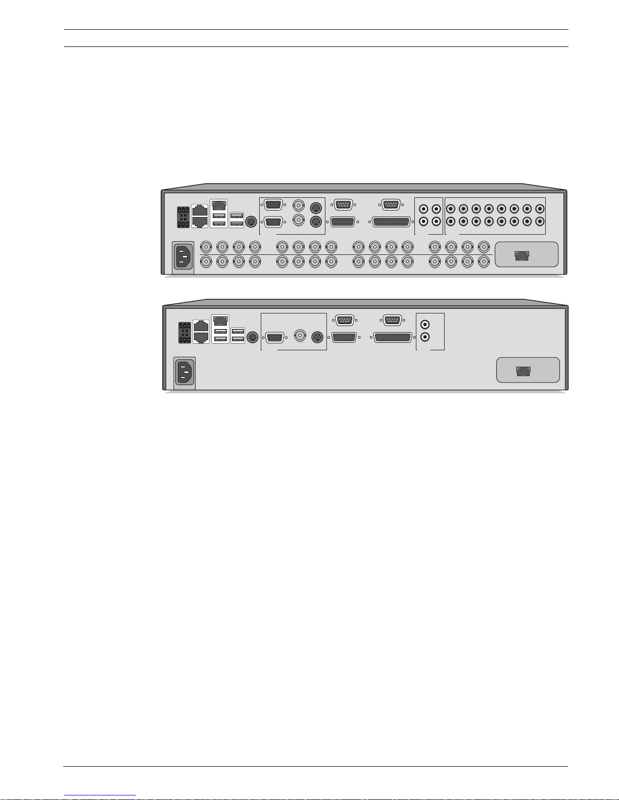
3.1 Connections
Figure 3.1 Back panel connections for hybrid and network versions
1. For hybrid versions, connect the cameras to the BNC Video in connectors (automatically
terminated).
2. Connect monitor A to the CVBS, Y/C, or VGA (supporting 1280x1024) output MON A.
3. Connect the USB mouse to a USB port.
4. Connect monitor B to the CVBS, Y/C, or VGA (supporting 1024x768) output MON B*.
5. Connect up to 16 audio signals to the RCA Audio in connectors*.
6. Connect the RCA Audio out connector(s) to a monitor or an audio amplifier.
7. Connect up to 16 inputs to the Alarm I/O via the 25-pin connector board.
8. Connect up to 4 alarm outputs to the Alarm I/O via the 25-pin connector board.
9. Connect the malfunction output (MAL OUT) via the screw terminal adapter.
10. Connect an Intuikey keyboard to the KBD in socket and connect the terminator (supplied
with the keyboard) to the KBD out socket.
11. Connect a Bosch pan/tilt/zoom control unit to the Biphase port (via the 15-pole D-type
connector board).
12. Connect a third-party pan/tilt/zoom control unit to the RS485 port (via the screw
terminal adapter).
13. Connect to your network via the Ethernet port. (Some versions have a Secondary
Ethernet port which can be used as a separate network connection.)
14. Connect your IP cameras to the network.
Switch on all connected equipment.
15. Connect the power cord to the unit.
KBD in
KBD out
IR ext
VGA
CVBS Y/C
Biphase
Com 1 Com 2
Alarm I/O
ABAA
BB
- | + | G
RS
485
MAL
OUT
N0 | C | NC
Video in
Video out
Video in
Video out
Video in
Video out
1234
1234
5678
5678
9 101112 13141516
9 101112 13141516
AC
USBUSB
Ethernet
Audio out Audio in
AB
L
R
13579111315
2
4
6
8
10
12
14
16
Monitor out
Secondary Ethernet
KBD in
KBD out
IR ext
VGA
CVBS Y/C
Biphase
Com 1 Com 2
Alarm I/O
- | + | G
RS
485
MAL
OUT
N0 | C | NC
AC
USBUSB
Ethernet
Audio out
A
L
R
Secondary Ethernet
Monitor out
18 en | Quick install Divar 700 Series
F.01U.246.471 | v3.4 | 2011.06 Installation and Operation manual Bosch Security Systems
3.2 First-time use
The unit first determines if camera inputs are PAL or NTSC and selects the output mode for
the monitor. If only IP cameras are connected, the system defaults to PAL. The unit starts with
a multiscreen display.
See Section 4.4 Camera connections, page 26 for more details and for instructions on
overriding the operating mode.
The Quick install menu opens the first time the unit is used. Fill in the basic settings in the
tabs to get the unit operational. The unit begins recording automatically when the Quick
install menu is closed.
To open the Quick install menu at any other time:
1. Press the menu button.
2. The main menu appears on monitor A.
3. Click Configuration and then Quick install.
Navigating
Use the USB mouse or the following front panel keys:
– Use the enter button to select a submenu or item.
– Use the arrow buttons to move through a menu or list.
– Use the escape button to go back or to switch off the menu.
Divar 700 Series Quick install | en 19
Bosch Security Systems Installation and Operation manual F.01U.246.471 | v3.4 | 2011.06
3.3 Quick install menu
The Quick install menu contains four tabs: International, Network, Schedule, and Recording.
Navigate through these tabs using Back and Next. Click Undo to cancel changes made in the
active tab. Click Close to exit the Quick install menu. Changing Quick install settings
overwrites customized settings.
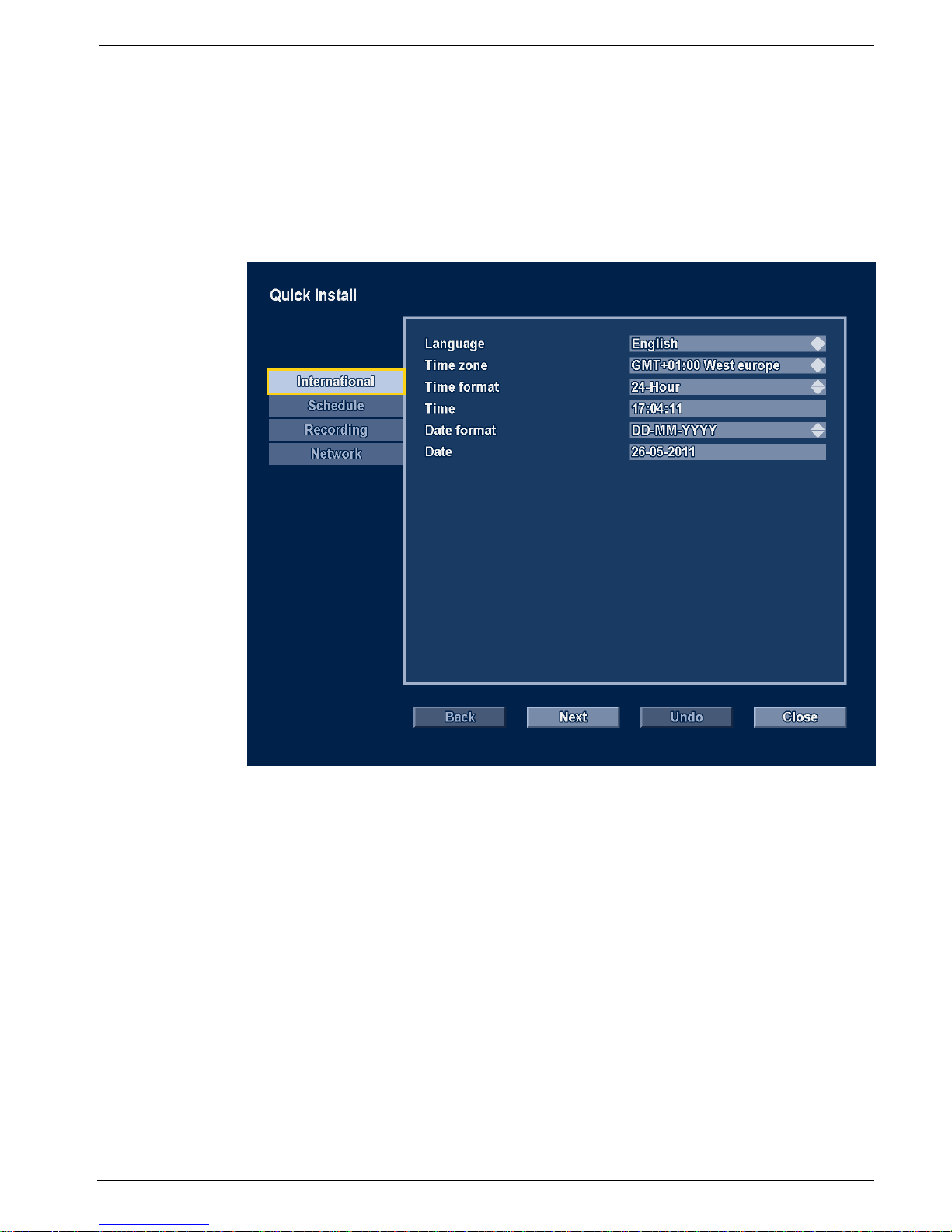
3.3.1 International
Figure 3.2 Quick install menu - International
Language — Select the language for the menu from the list.
Time zone — Select a time zone from the list.
Time format — Select either a 12 or a 24 hour clock format.
Time format — Fill in the current time.
Date format — Select a date format with month (MM), day (DD), or year (YYYY) first.
Date — Fill in the current date.
20 en | Quick install Divar 700 Series
F.01U.246.471 | v3.4 | 2011.06 Installation and Operation manual Bosch Security Systems
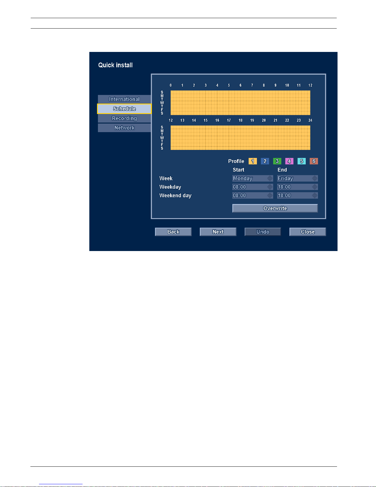
3.3.2 Schedule
Figure 3.3 Quick install menu - Schedule
The currently active weekly schedule is shown. Each color represents an available profile:
– Yellow - Profile 1
– Dark blue - Profile 2
– Green - Profile 3
–Pink - Profile 4
– Light blue - Profile 5
– Brown - Profile 6
Click Overwrite to start making changes.
– Select on which day the week should start and end.
– Select when the day begins and ends on weekdays.
– Select when the day begins and ends on weekends.
The display is automatically updated when settings are changed.
Divar 700 Series Quick install | en 21
Bosch Security Systems Installation and Operation manual F.01U.246.471 | v3.4 | 2011.06
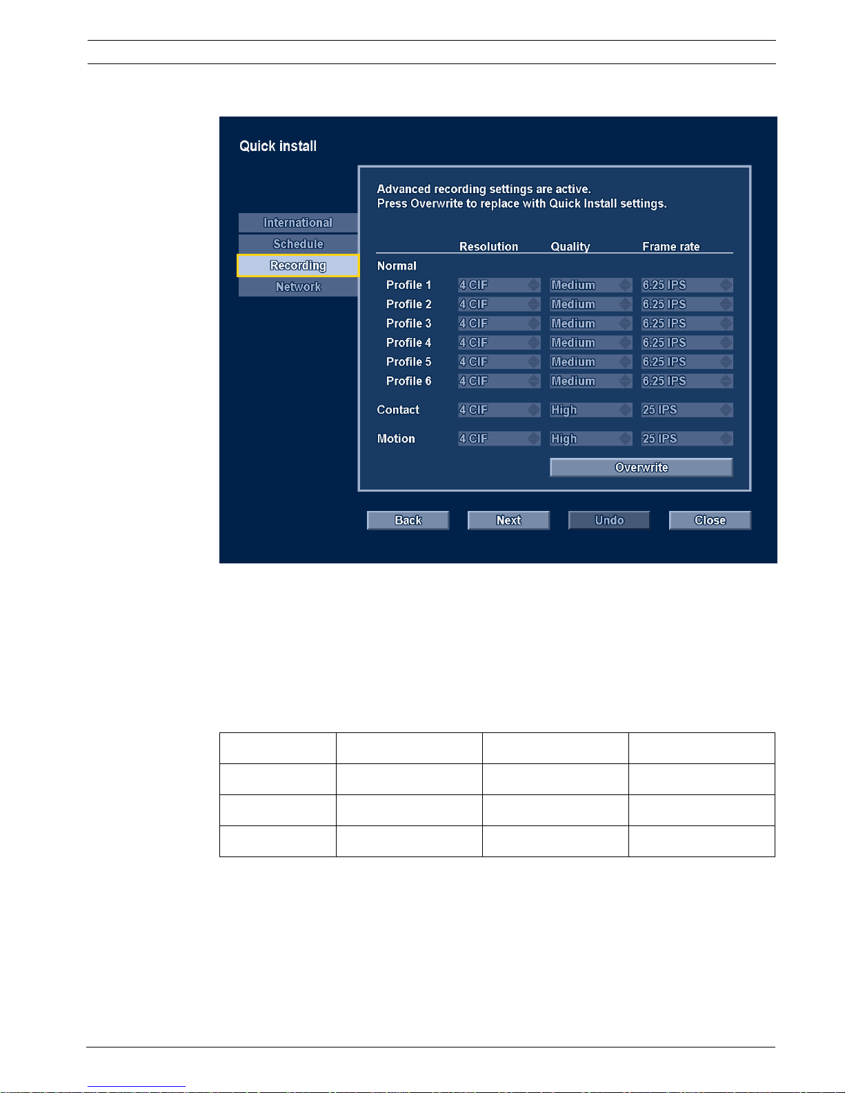
3.3.3 Recording
Figure 3.4 Quick install menu - Recording
Set the Normal recording Resolution, Quality, and Frame rate for each profile in the table. Set
the Alarm and Motion recording Resolution, Quality, and Frame rate. These settings are set for
all profiles. If advanced settings were previously made, click Overwrite to replace them with
Quick install settings.
Note:
The resolution selection shows only CIF, 2CIF or 4CIF resolutions. When selecting one of
these for a camera that supports different resolutions, the following conversions apply:
The recording panel shows when conversions are applied and when bitrate limitations are
enforced due to bandwidth management settings.
Setting QVGA/VGA cameras 1080p/720p cameras 720p cameras
CIF QVGA 720p 720p
2CIF QVGA 720p 720p
4CIF VGA 720p 720p
22 en | Quick install Divar 700 Series
F.01U.246.471 | v3.4 | 2011.06 Installation and Operation manual Bosch Security Systems
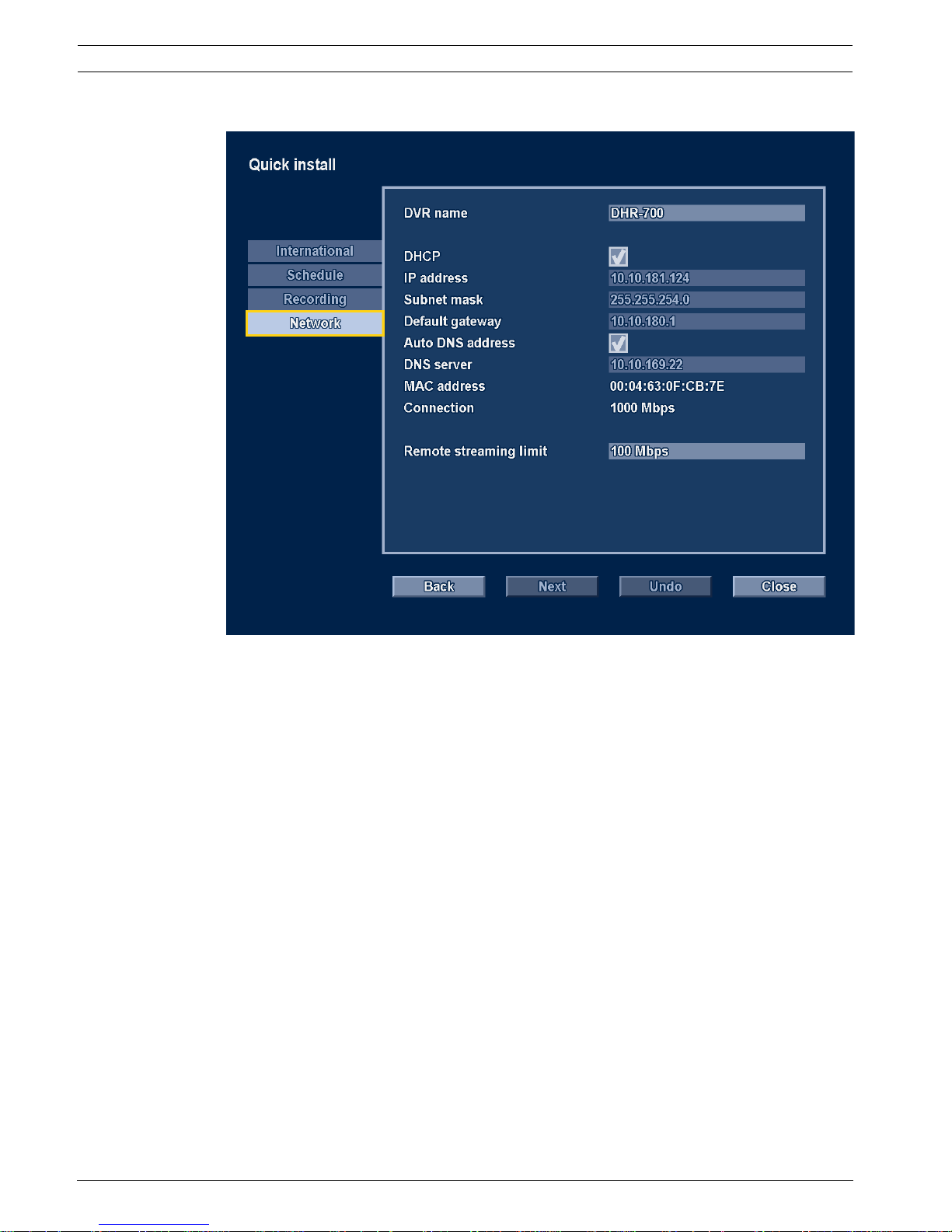
3.3.4 Network
Figure 3.5 Quick install menu - Network
Fill in the settings that control the behavior of the unit with respect to a network.
DVR name — Enter a unique DVR name to be used in the network.
DHCP — Enable DHCP to have IP address, Subnet mask, and Default gateway assigned
automatically by the DHCP server of the network. The actual values are displayed.
IP address — Fill in the IP address when DHCP is not enabled.
Subnet mask — Fill in the Subnet mask when DHCP is not enabled.
Default gateway — Fill in the Default gateway when DHCP is not enabled.
Auto DNS address — Enable to have the DNS server IP address assigned automatically. The
assigned address is displayed.
DNS server — Fill in the DNS server address when Auto DNS address is not enabled.
MAC address — The MAC address is read only.
Connection — Shows current network speed of the primary Ethernet connection.
Remote streaming limit — Enter a value between 0 and 1000 Mbps to restrict the network
bandwidth available for streaming audio and video to all BVC workstations combined.
Divar 700 Series Hardware setup | en 23
Bosch Security Systems Installation and Operation manual F.01U.246.471 | v3.4 | 2011.06
4 Hardware setup
This chapter contains detailed information about the hardware installation and connection of
external equipment to the unit. The connector types and their pin signals are described. Most
of the connectors are located at the rear panel of the unit. For convenience, a USB port is
located on the front of the unit to connect a mouse or memory device.
All the input/output ports are Safety Extra Low Voltage (SELV) circuits. SELV circuits should
only be connected to other SELV circuits.
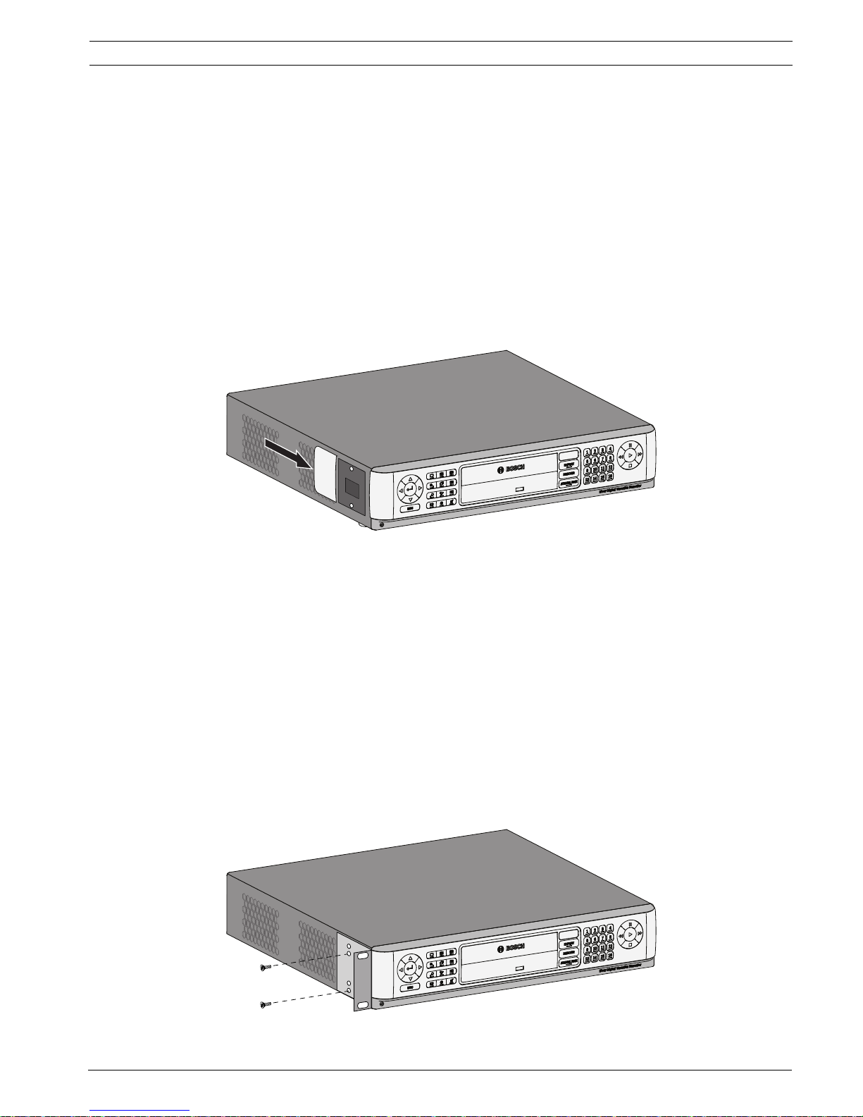
4.1 Desktop installation
Place the unit on a stable, flat surface. Install the two silver side covers:
1. insert a cover on each side.
2. Slide the cover towards the front of the unit.
Figure 4.1 Side cover installation
4.2 Rack mounting
The unit can be mounted in a 19-inch rack. A rack mounting kit is supplied with the unit that
includes two rack mounting brackets.
Mounting
1. Remove the four cross head screws (two on each side) located near the front panel on
the right and left side of the unit.
2. Secure the supplied brackets to each side using the same four cross head screws (two
on each side) that were just removed.
3. To install several units directly on top of each other, remove the rubber feet from under
the unit by prying them loose with a small screwdriver.
4. Install the unit into the rack using the hardware supplied with the rack and following the
rack manufacturer’s instructions.
Figure 4.2 Securing the rack mounting bracket
24 en | Hardware setup Divar 700 Series
F.01U.246.471 | v3.4 | 2011.06 Installation and Operation manual Bosch Security Systems
4.3 Hard disk installation
Up to four hard disks can be installed in the DVR. All hard disks are accessed from the front of
the unit by removing the front panel. Do not open the top cover or attempt to service the unit.
No user serviceable parts inside. Refer all servicing to qualified service personnel. Improper
handling or installation could void the warranty of both the hard disk and the DVR.
Note:
Only genuine Bosch hard disks will work in the Divar 700 Series. See the Bosch website or
contact your local Bosch representative for available hard disks.
Installing or removing hard disks does not breach the warranty conditions as long as the
warranty label is not broken.
4.3.1 Mounting instructions
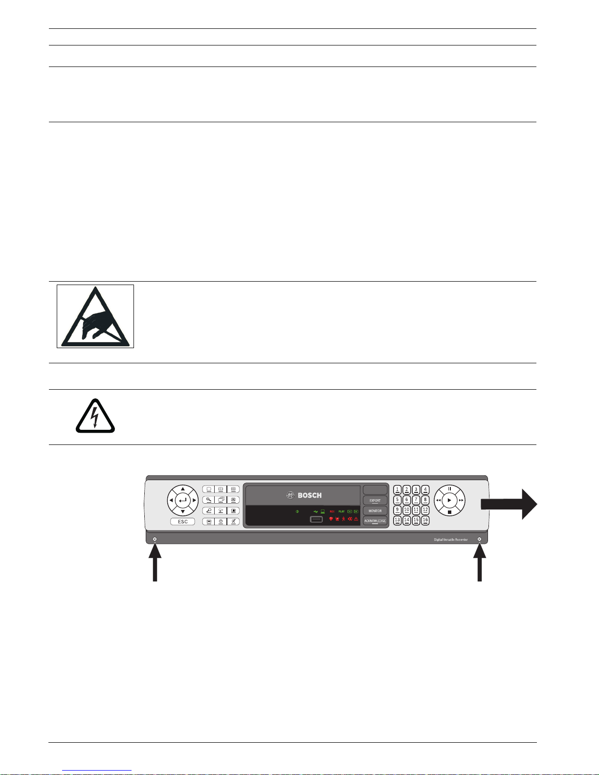
Removing the front panel
Figure 4.3 Front panel removal
1. Loosen the two captive cross head screws on the bottom front panel.
2. Slide the front panel to the right until it is free.
3. Place the front panel on top of the unit, taking care not to strain the flat cable. If there is
no room on top of the unit, disconnect the flat cable and set the front panel aside.
CAUTION!
When installing the assembly into the rack, do not restrict air flow around the vents located on
the side panels or exceed the recommended operating temperature.
Secure the connection cables to the rack to relieve excessive weight to the back of the unit.
CAUTION!
Electrostatic discharges
Any electrostatic energy coming in contact with the hard disk or other sensitive internal parts
can damage them permanently. Improper handling could void the warranty of the hard disk.
When working with electrostatic sensitive devices such as a hard disk or the Divar unit, make
sure to use a static-free workstation.
DANGER!
Electrical voltage. Risk of electric shock.
Before installation of the hard disk, unplug the power cord of the DVR and wait for at least 30
seconds.
Divar
Divar 700 Series Hardware setup | en 25
Bosch Security Systems Installation and Operation manual F.01U.246.471 | v3.4 | 2011.06
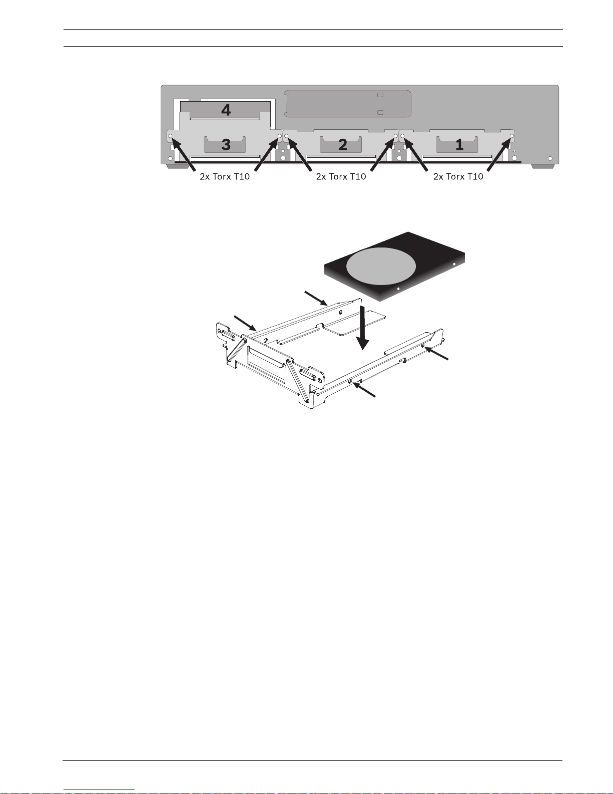
Placing a hard disk
Figure 4.4 Placing a hard disk
1. Locate the first empty hard disk bay. It is recommended to install the disks in order from
one to four, as labeled. (Note that disks 3 and 4 are mounted in a double bay.)
2. Unscrew the two torx T10 screws securing the selected bay. Slide the bay from the unit
by pulling it forward.
3. To replace an installed hard disk, remove the four installation screws, two per side, from
the sides of the bay. Remove the hard disk.
Mount the new hard disk into the bay with four screws, two per side (refer to the hard
disk documentation).
4. Align and slide the bay back fully into its slot in the unit.
5. Secure the bay using the two torx T10 screws removed earlier (step 2).
6. Repeat steps 1-5 for any additional hard disks.
Remounting the front panel
1. When disk installation is complete, reconnect the flat cable to the front panel, if
necessary.
2. Align and slide the front panel to the left until it is in place.
3. Refasten the two captive cross head screws to the front panel.
The location of the hard disks is not important; the unit can determine in which bay they are
installed. When installing hard disks that have recordings from another unit, the recorder
detects this and puts these drives in read-only mode.
Refer to Section 6.10 Storage, page 95 for the correct configuration procedure.

26 en | Hardware setup Divar 700 Series
F.01U.246.471 | v3.4 | 2011.06 Installation and Operation manual Bosch Security Systems
4.4 Camera connections
On hybrid units, connect cameras to the Video in connectors on the back of the unit using
75 ohm video coaxial cables with BNC connectors. Optionally, this signal can be looped
through to other equipment via the corresponding Video out connector. The camera input
connectors are auto-terminating. There is no need to add a terminator to the output
connector if no additional equipment is connected.
If the camera signal is looped-through to additional equipment, make sure that the end of the
video connection is terminated with 75 ohm termination.
The unit automatically configures itself as a PAL or NTSC unit. The unit determines the
standard by detecting the signal format of the first connected camera (lowest camera input
number).
On network units, or hybrid units with no analog cameras connected, the detection process
fails and the recorder configures itself as a PAL unit. In this case, no video is visible on an
NTSC monitor.
To change this behaviour select a preferred video mode during start-up.
– For PAL, press the monitor and camera 1 buttons simultaneously for ten seconds during
power-up.
– For NTSC, press the monitor and camera 2 buttons simultaneously for ten seconds
during power-up.
The unit retains these manual settings on subsequent start-ups.
Specifications
Input signal: Composite video 1 Vpp, 75 ohm
Color standard: PAL/NTSC, auto-detect
Gain control: Automatic or manual gain control for each video input
Connector type: BNC looped-through, automatic termination
Figure 4.5 Eight video inputs with loop-through outputs
Video in
Video out
1234
1234
5678
5678
Divar 700 Series Hardware setup | en 27
Bosch Security Systems Installation and Operation manual F.01U.246.471 | v3.4 | 2011.06
4.5 Audio connections (hybrid version only)
The unit supports up to 16 audio inputs and 4 audio outputs. Connect using audio cable with
RCA compatible connectors.
Specifications
Input signal: Mono RCA, 1 Vpp, 10k ohm
Output signal: Dual mono RCA, 1 Vpp, 10k ohm
Figure 4.6 Audio input connectors
Figure 4.7 Audio output connectors
4.6 Monitor connections
On the hybrid version up to two monitors can be connected through the VGA, CVBS, or Y/C
connections. A single monitor can be connected on the network version.
Note:
HD models provide HD recording but not HD local display. Use the Bosch Video Client to
display live HD cameras and SD cameras with Main Profile streams, and recorded video from
these cameras.
4.6.1 VGA
Connect the unit to the monitor using standard VGA cable.
Note:
17-inch or 19-inch LCD monitors with an aspect ratio of 4:3 are recommended.
Specifications
Output signal: VGA
Resolution: 1280 x 1024 (monitor A), 1024 X 768 (monitor B)
Color: True color (32 bit)
Connector type: DE-15
Figure 4.8 VGA monitor connectors (hybrid version)
Audio in
13579111315
2
4
6
8
10
12
14
16
Audio out
AB
L
R
VGA
A
B

28 en | Hardware setup Divar 700 Series
F.01U.246.471 | v3.4 | 2011.06 Installation and Operation manual Bosch Security Systems
4.6.2 CVBS
Connect the unit to CCTV monitors using 75 ohm video coaxial cables with BNC connectors.
The unit provides a 1 Vpp CVBS signal.
If the monitor has a loop-through connection without using the loop-through output, then
select the 75 ohm impedance setting on the monitor. If the monitor's loop-through output is
connected to an additional device, the device's termination is set to 75 ohm and the monitor's
termination is set to high impedance. (This is not necessary on devices with automatic
termination.)
Specifications
Output signal: Composite video 1Vpp, 75 ohm, Sync. 0.3Vpp ±10%
Resolution: 704 x 576 PAL, 704 X 480 NTSC
Connector type: BNC
Figure 4.9 CVBS monitor connectors (hybrid version)
4.6.3 Y/C
Connect the unit to a CCTV monitor with Y/C input, using a standard Y/C connection cable.
Figure 4.10 Y/C monitor connectors (hybrid version)
4.7 Monitor streaming connection (hybrid version)
To connect a monitor in a remote streaming configuration, connect the CVBS monitor output
to a video input. Then connect the monitor to the corresponding loop-through connector.
Figure 4.11 Typical monitor streaming connection (hybrid version)
CVBS
A
B
Y/C
A
B
KBD in
KBD out
IR ext
VGA CVBS Y/C Biphase
Com 1 Com 2
Alarm I/O
ABAA
BB
- | + | G
RS
485
MAL
OUT
N0 | C | NC
Video in
Video out
Video in
Video out
Video in
Video out
1234
1234
5678
5678
9 101112 13141516
9 101112 13141516
AC
USBUSB
Ethernet
Audio out Audio in
AB
L
R
13579111315
246810121416
Monitor out
B
A
Divar 700 Series Hardware setup | en 29
Bosch Security Systems Installation and Operation manual F.01U.246.471 | v3.4 | 2011.06
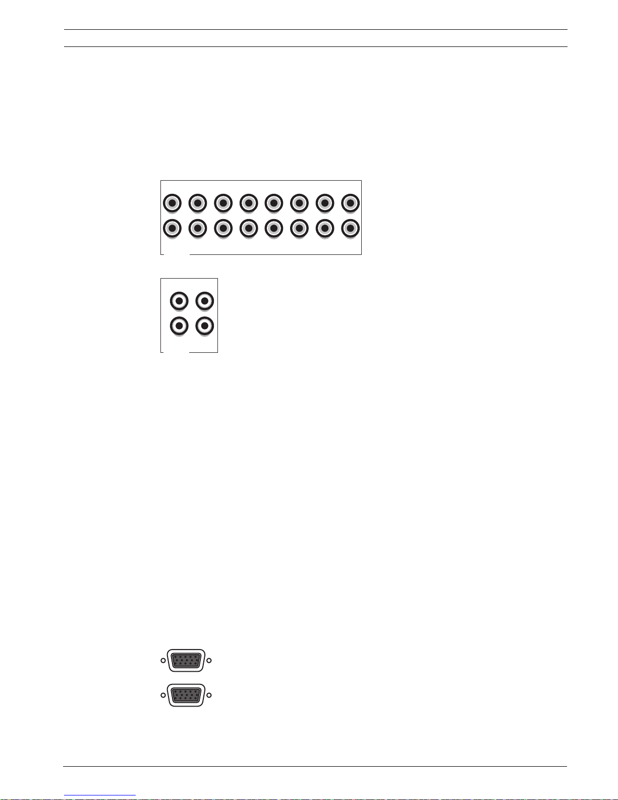
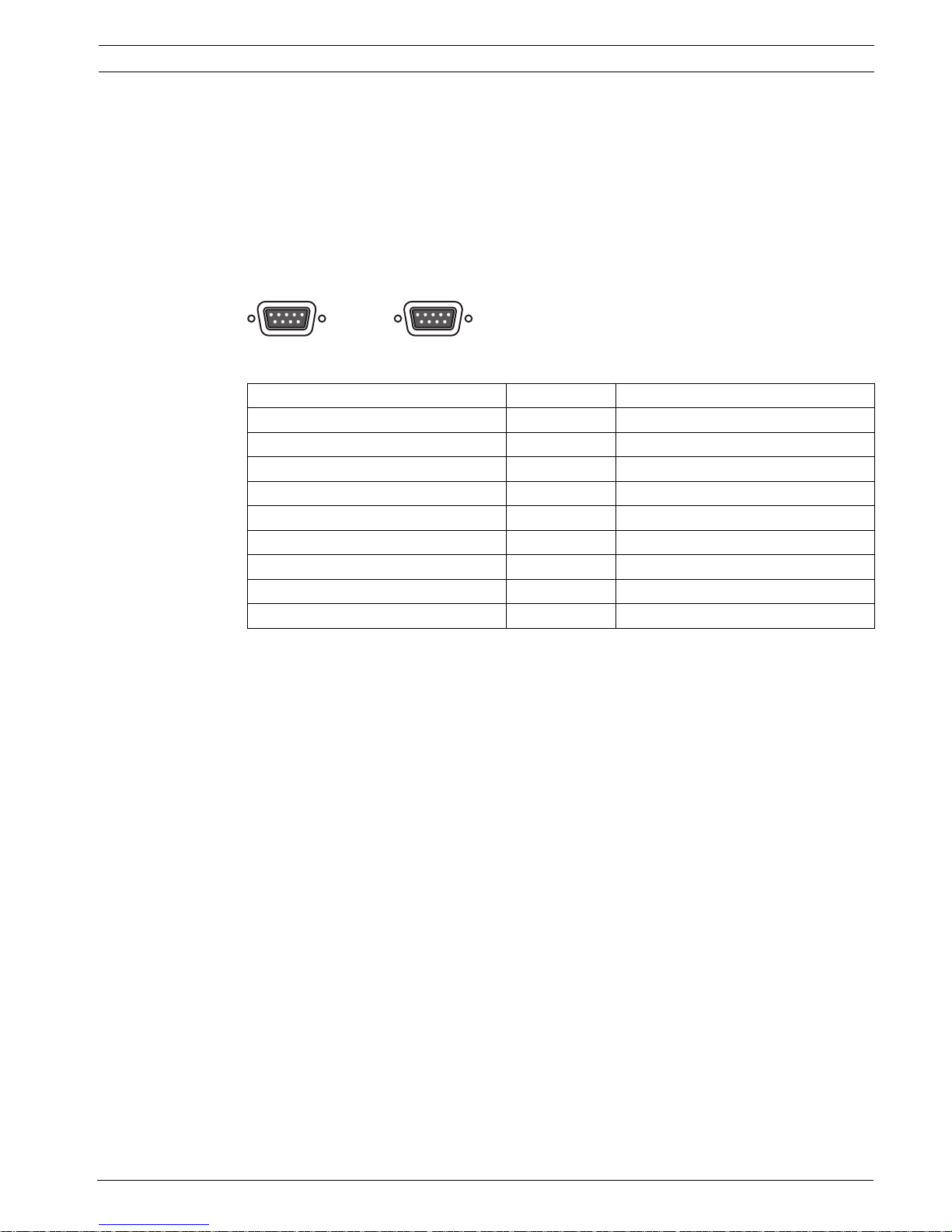
4.8 RS232 COM port connections
The RS232 COM ports are used to connect a PC to the unit for service purposes. Use a nullmodem cable to connect the serial port of the PC to the unit. The Baud rate can be selected in
the menu system.
Specifications
Connector type: 9-pole D-type male connector
Maximum input voltage: ±25V
Communicaton protocol: Output signals according EIA/TIA-232-F
Figure 4.12 RS232 COM port connectors
Tab le 4. 1 RS232 console port socket
Signal name Pin number Description
DCD_in 1 Carrier detection signal (not used)
RX 2 RS232 receive signal
TX 3 RS232 transmit signal
N/C 4 No connection
System ground 5 System ground
N/C 6 No connection
RTS 7 RS232 request to send signal
CTS 8 RS232 clear to send signal
N/C 9 No connection
COM 1 COM 2

30 en | Hardware setup Divar 700 Series
F.01U.246.471 | v3.4 | 2011.06 Installation and Operation manual Bosch Security Systems
4.9 Keyboard connections
The keyboard input and output connectors are used to connect a Bosch Intuikey keyboard to
one or more units. For one unit, connect the keyboard to the KBD in connector. For more
units, connect a cable between the KBD out connector of the first unit and the KBD in
connector of the following unit. Up to 16 Divar 700 units can be connected and controlled in
this manner with one keyboard. Additionally up to 10 Divar 2 recorder units can be operated
with the same keyboard.
The following accessories are available:
– For short distances (up to 30 m), standard 6-core telecom flat cable can be used to
supply power and signal connections for the keyboard (LTC 8558/00).
– For distances over 30 m between the keyboard and the DVR, the Keyboard Extension Kit
(LTC 8557) must be used. This kit provides junction boxes, cables, and the appropriate
power supply for the external keyboard. The recommended cable type is Belden 8760 or
equivalent.
– By using a keyboard Port Expander unit (LTC 2604) up to 4 Intuikey keyboards can
operate recorder units.
– With the Video Manager (LTC 2605), up tp 16 Divar recorders and up to 6 monitors can
be operated from 1 to 4 separate Intuikey keyboards.
Termination
Connect the keyboard terminator (supplied with the Intuikey keyboard) to the KBD out
connector. If multiple units are controlled with a single keyboard, the KBD out connector of
the last unit must be terminated.
Specifications
Communicaton protocol: RS485
Maximum signal voltage: ± 12V
Power supply: 11 - 12.6 VDC, maximum 400 mA
Maximum cable length: 30 meters (using standard 6-core telecom flat cable), or 1.5
kilometers (using Belden 8760 or equivalent in combination with the LTC 8557).
Cable type: black (cross-over) cable (supplied with keyboard)
Termination: 390 ohm terminator
Figure 4.13 Keyboard input and output connectors
Tab le 4. 2 Keyboard In - RJ11 socket (KBD in)
Pin number Signal
1 +12 VDC (11 V Min to 12.6 V Max, 400 mA Max)
2 System ground
3 Keyboard plus line
4 Keyboard minus line
5 System ground
6 System ground
KBD IN
KBD OUT
 Loading...