Bosch DS7457I, DS7457IF Installation Manual

Installation Instructions
for the
DS7457i and DS7457iF Single Zone Input Modules
1.0Description
The DS7457i/DS7457iF are Single Zone Input Modules designed to operate with compatible multiplex systems. It provides a supervised input zone for connection of conventional normally open or normally closed inputs. Each DS7457i/DS7457iF occupies one multiplex zone address on the system. The DS7457i/DS7457iF connect to the DS7430 or DS7436 Multiplex Expansion Modules or the D8125MUX Multiplex Expansion Module. For additional DS7457i and DS7457iF installation information, refer to the D9412GV2/ D7412GV2 Approved Applications Compliance Guide (P/N: F01U003639) and the D8125MUX Operation and Installation Guide
(P/N: F01U034973).
2.0 Specifications
• Module Requirements: The DS7457i/DS7457iF is designed to work with the following multiplex modules:
- DS7430 Multiplex Expansion Module
- DS7436 Multiplex Expansion Module.
- D8125MUX Multiplex Expansion Module
• Line Impedance:
|
|
|
|
|
|
|
|
|
250 ft |
|
22 AWG |
|
600 ft |
|
18 AWG |
|
76 m |
|
0.65 mm |
|
193 m |
|
1.02 mm |
|
Fire applications require 18 AWG. |
|
|
• Voltage: 12 VDC nominal |
|
||
• Current Draw: 0.5 mA maximum |
|
||
• Zone Response Time: 400 ms |
|
||
• Operating Temperature Range: +32°F to +122°F (0°C to +50°C) |
|
||
• Relative Humidity: 0% to 93% |
|
||
• Signaling Line Circuit Type: Class B (Style 4) |
|
||
• Initiating Device Circuit Type: Class B (Style A) |
|
||
When used in a fire system, NFPA 72 prohibits this product from sharing a communications bus with non-fire devices.
3.0Programming
Consult the intended control panel's installation guide for multiplex zone (point) programming information. See page 4 for switch settings.
4.0 Installation
After any programming or hardware change, do a functional test of the system as required by local codes.
These Installation Instructions assume the control panel is installed and in proper working condition.
The control panel must be programmed and the DS7457i/DS7457iF address switches must be set for the DS7457i/ DS7457iF to operate.
•Program the control panel as described in the panel's Reference Guide.
Disconnect power to the panel before running wires to connect the DS7457i/DS7457iF.
•The DS7457i/DS7457iF is compact enough to fit within most backboxes and enclosures.

5.0 Wiring
DS7457i/iF |
Description |
Terminals |
|
RED |
Positive Multiplex Input |
BLACK |
Negative Multiplex Input |
YELLOW |
Protection Zone Positive Input |
BLACK |
Protection Zone Ground |
Table 1: DS7457i/DS7457iF Terminal Descriptions
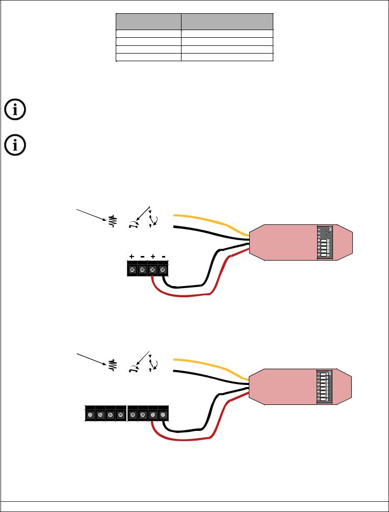
•Connect wiring to the DS7457i/DS7457iF as shown in Figures 1- 3.
•Protection zones are designed to monitor Normally Open or Normally Closed dry contacts. They are supervised using 47K ohm end- of-line resistors.
The input zones are power limited and supervised.
When used in fire applications, Normally Open contacts must be used on the input zones.
5.1 DS7430 Multiplex Expansion Module Wiring
Use 47K ohm EOL P/N:26069 |
|
Alarm Contact |
|
|
|
|
|
||
on the DS7457i for non-fire applications. |
|
|
|
|
|
|
|||
|
(Normally Open or |
|
|
|
|
|
|||
Use 47K ohm EOL P/N:28010 |
|
|
|
|
|
|
|||
|
Normally Closed) |
|
|
|
|
|
|||
on the DS7457iF for fire applications. |
|
|
|
|
|
|
|||
|
|
|
YELLOW |
|
|
|
|
||
|
|
|
|
|
|
|
|
|
|
|
|
|
|
N/O |
|
|
|
|
|
|
|
|
|
|
|
|
|
|
|
|
|
N/C |
|
|
|
|
|
||
|
|
|
|
|
|
|
|||
|
|
|
|
|
|
|
|||
|
|
|
|
|
BLACK |
|
|
|
|
|
|
|
|
|
|
|
|
|
|
|
|
|
|
|
|
|
|
|
|
DS7430
Power Bus
BLACK
RED
Figure 1: Wiring to a DS7430 Multiplex Expansion Module
5.2 DS7436 Multiplex Expansion Module Wiring
Use 47K ohm EOL P/N:26069 |
|
Alarm Contact |
||
on the DS7457i for non-fire applications. |
|
|||
|
(Normally Open or |
|||
Use 47K ohm EOL P/N:28010 |
|
|||
|
Normally Closed) |
|||
on the DS7457iF for fire applications. |
|
|||
|
|
|
||
|
|
|
|
|
|
|
|
|
N/O |
|
|
|
|
|
|
|
N/C |
||
DS7436
PWR+ PWRBUS+ BUSPWR+ PWRBUS+ BUS-
Either Bus A or Bus B, or both, may be used. Refer
to the panel’s reference guide.
YELLOW
BLACK
BLACK
RED
Page 2 |
© 2008 Bosch Security Systems, Inc. |
DS7457i/DS7457iF Installation Instructions |
 Loading...