


DKE 995 P
de Gebrauchsund Montageanweisung
en Operating and installation instructions
fr Mode d’emploi et notice de montage
nl Gebruiksaanwijzing en montagevoorschrift
it Istruzioni d’uso
e per il montaggio es Instrucciones de uso
y de montaje
pt Instruções de serviçio e de montagem
sv Bruksoch Monteringsanvisning
no Bruksog Monteringsanvisning
fi Käyttöoja Asennusohje
da Brugsog montagevejledning
Internet: http://www.bosch-hausgeraete.de
Bosch Info-Team: de Tel. 01 80/5 30 40 50 (E 0,12/Min. DTAG)
a
de
en
fr
nl
it
es
Seite |
03 – 15 |
page |
16 – 28 |
pages |
29 – 41 |
pagina |
42 – 54 |
pagina |
55 – 67 |
página |
68 – 80 |
pt
sv
no
fi
da
página |
081 – 093 |
sid |
094 – 106 |
side |
107 – 119 |
Sivu |
120 – 132 |
side |
133 – 145 |
Abb. 1 |
Abb. 1 |
GAS |
ELEKTRO |
GAZ |
ELECTR. |
KAASU |
ELETT. |
GASS |
EL. |
|
|
mind. |
mind. |
650 |
550 |
2
Gebrauchsanweisung:
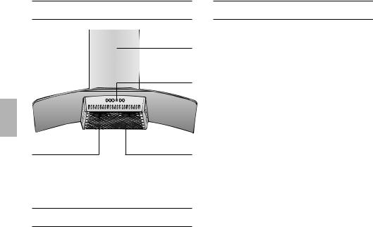
Gerätebeschreibung
|
Kamin- |
|
verblendung |
|
Schalter |
|
Licht/Lüfter |
Beleuchtung |
Filtergitter |
Betriebsarten
Abluftbetrieb:
Der Lüfter der Dunstabzugshaube saugt den Küchendunst an und
leitet ihn durch den Fettfilter ins Freie.
Der Fettfilter nimmt die fettigen Bestandteile des Küchendunstes auf.
Die Küche bleibt weitgehend frei von Fett und Geruch.
DBei Abluftbetrieb der Dunstabzugshaube und gleichzeitigem Betrieb schornsteinabhängiger Feuerungen (wie z. B. Gas-, Öloder Kohleheizgeräte, Durchlauferhitzer, Warmwasserbereiter) muss für ausreichend Zuluft gesorgt werden, die von der Feuerstätte zur Verbrennung benötigt wird.
Ein gefahrloser Betrieb ist möglich, wenn der Unterdruck im Aufstellraum der Feuerstätte von 4 Pa (0,04 mbar) nicht überschritten wird.
Betriebsarten
Dies kann erreicht werden, wenn durch nicht verschließbare Öffnungen, z. B. in Türen, Fenstern und in Verbindung mit Zuluft-/Abluftmauerkasten oder durch andere techn. Maßnahmen, wie gegenseitige Verriegelung o. ä., die Verbrennungsluft nachströmen kann.
Bei nicht ausreichender Zuluft besteht Vergiftungsgefahr durch zurückgesaugte Verbrennungsgase.
Ein Zuluft-/Abluftmauerkasten allein stellt die Einhaltung des Grenzwertes nicht sicher.
Anmerkung: Bei der Beurteilung muss immer der gesamte Lüftungsverbund der Wohnung beachtet werden. Bei Betrieb von Kochgeräten, z. B. Kochmulde und Gasherd wird diese Regel nicht angewendet.
Wenn die Dunstabzugshaube im Umluftbetrieb – mit Aktivkohlefilter – verwendet wird, ist der Betrieb ohne Einschränkung möglich.
Umluftbetrieb:
Hierzu muss ein Aktivkohlefilter einge-
baut werden (siehe Filter und Wartung).
Das komplette Montage-Set sowie die Ersatzfilter können Sie beim Fachhandel erwerben.
Die entsprechenden Zubehör-Nummern finden Sie am Ende dieser Gebrauchsanweisung.
Der Lüfter der Dunstabzugshaube saugt den Küchendunst an und leitet ihn durch den Fettund Aktivkohlefilter gereinigt in die Küche zurück.
Der Fettfilter nimmt die fettigen Bestandteile des Küchendunstes auf.
Der Aktivkohlefilter bindet die Geruchsstoffe.
3
Vor dem ersten Benutzen
Wichtige Hinweise:
Diese Gebrauchsanweisung gilt für mehrere Geräte-Ausführungen.
Es ist möglich, dass einzelne Ausstattungsmerkmale beschrieben sind, die nicht auf Ihr Gerät zutreffen.
Diese Dunstabzugshaube entspricht den einschlägigen Sicherheitsbestimmungen.
Reparaturen dürfen nur von Fachkräften durchgeführt werden.
Durch unsachgemäße Reparaturen können erhebliche Gefahren für den Benutzer entstehen.
Ist das Gerät beschädigt, dürfen Sie es nicht in Betrieb nehmen.
Anschluss und Inbetriebnahme dürfen nur von einem Fachmann durchgeführt werden.
Verpackungsmaterial ordnungsgemäß entsorgen (siehe Montageanweisung).
Dunstabzugshaube nur mit eingesetzten Lampen betreiben.
Defekte Lampen sollten sofort ersetzt werden, um Überlastung der restlichen Lampen zu vermeiden.
Dunstabzugshaube nie ohne Fettfilter betreiben.
Überhitzte Fette oder Öle können sich leicht entzünden.
Darum Speisen mit Fetten oder Ölen, z. B. Pommes frites, nur unter Aufsicht zubereiten.
Bevor Sie das neue Gerät benutzen, lesen Sie bitte sorgfältig die Gebrauchsanweisung.
Sie enthält wichtige Informationen für Ihre Sicherheit sowie zum Gebrauch und zur Pflege des Gerätes.
Bewahren Sie die Gebrauchsund Montageanweisung ggf. für einen Nachbesitzer gut auf.
Unter der Dunstabzugshaube nicht flambieren.
!Brandgefahr am Fettfilter durch aufsteigende Flammen.
Über einer Feuerstätte für feste Brennstoffe (Kohle, Holz und dgl.) ist der Betrieb der Dunstabzugshaube nur bedingt gestattet (siehe Montageanweisung).
Gas-Kochmulden / Gas-Herde
Gas-Kochstellen immer sachgemäß benutzen.
Wichtig:
Die Flammen der Gas-Kochstellen müssen immer mit Kochgeschirr abgedeckt sein.
Durch die starke Hitzeentwicklung
!der offenen Gasflammen könnte die Dunstabzugshaube beschädigt werden.
Die während des Betriebes entstehende Wärmebelastung aller Kochstellen darf
8,0 kW nicht überschreiten, unabhängig von der installierten Nennleistung.
Ausnahme:
Kurzzeitig (max. 15 Minuten) können die Kochstellen mit einer Wärmebelastung bis zu 11,3 kW betrieben werden, wenn mindestens die Lüfterstufe 2 ständig eingeschaltet ist. (Sonst besteht Verbrennungsgefahr bei Berührung der Gehäuseoberflächen).
4
Bedienen der Dunstabzugshaube
Der Küchendunst wird am wirkungsvollsten beseitigt durch:
Einschalten der Dunstabzugshaube bei Kochbeginn.
Ausschalten der Dunstabzugshaube erst einige Minuten nach Kochende.
|
|
|
|
|
|
|
|
|
|
|
|
|
|
|
|
|
|
|
|
|
|
|
|
|
|
|
|
|
|
|
|
|
|
|
|
|
|
|
|
|
|
|
|
|
|
|
|
|
|
|
|
|
|
|
|
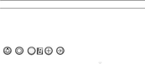
Licht |
|
|
|
|
Anzeige |
|
|
Lüfter- |
|||||
|
|
|
|
|
|
|
Lüfterstufen |
|
nachlauf |
||||
|
|
|
|
|
|
|
|
|
|
|
|||
Lüfter – Aus |
|
Lüfter zurück- |
Lüfter ein- |
||||||||||
|
|
|
|
|
schalten |
und hoch- |
|||||||
|
|
|
|
|
|
|
|
|
|
|
schalten |
||
Signalton:
Beim Drücken auf ein Symbol ertönt zur Bestätigung ein Signalton.
Ausschalten des Signaltons:
Drücken Sie gleichzeitig die Symbole 0 und + bis nach ca. 3 Sekunden ein Signal ertönt.
Einschalten des Signaltons:
Wiederholen Sie den Vorgang.
Einschalten des Lüfters:
Drücken Sie das Symbol +.
Einstellen der gewünschten Lüfterstufe:
Drücken Sie das Symbol +.
Der Lüfter schaltet eine Stufe höher.
Drücken Sie das Symbol –.
Der Lüfter schaltet eine Stufe zurück.
Ausschalten des Lüfters:
Drücken Sie das Symbol 0.
Die Anzeige { erlischt nach kurzer Zeit.
Oder:
Drücken Sie das Symbol – so oft, bis der
Lüfter ausschaltet.
Die Anzeige { erlischt nach kurzer Zeit.
Intensivstufe:
Durch die Intensivstufe wird die höchste Leistung erreicht. Sie wird kurzzeitig benötigt.
Drücken das Symbol + so oft, bis die Anzeige ç leuchtet.
Wird die Intensivstufe nicht von Hand
ausgeschaltet, schaltet der Lüfter nach 10 Minuten selbsttätig auf Stufe } zurück.
Lüfternachlauf:
Drücken Sie das Symbol  .
.
Der Lüfter läuft 10 Minuten in Stufe |, dabei blinkt in der Anzeige ein Punkt. Danach schaltet der Lüfter selbsttätig aus.
Beleuchtung:
Drücken Sie kurz das Symbol a zum Einund Ausschalten.
Die Beleuchtung kann zu jeder Zeit verwendet werden, auch wenn der Lüfter ausgeschaltet ist.
Einstellen der Helligkeit:
Halten Sie das Symbol a gedrückt, bis die gewünschte Helligkeit erreicht ist.
Automatisches Einschalten der Beleuchtung, z. B. über eine Zeitschaltuhr:
Lüfter und Beleuchtung müssen ausgeschaltet sein.
Einschalten:
Drücken Sie gleichzeitig die Symbole
– und !.
Nach ca. 3 Sekunden schaltet sich zur Bestätigung die Beleuchtung ein.
Ausschalten:
Wiederholen Sie den Vorgang bei eingeschalteter Beleuchtung.
Nach ca. 3 Sekunden schaltet sich zur Bestätigung die Beleuchtung aus.
5
Filter und Wartung
Fettfilter:
Zur Aufnahme der fettigen Bestandteile des Küchendunstes sind MetallFettfilter eingesetzt.
Die Filtermatten bestehen aus unbrennbarem Metall.
Achtung:
Bei zunehmender Sättigung mit fetthaltigen Rückständen erhöht sich die Entflammbarkeit und die Funktion der Dunstabzugshaube kann beeinträchtigt werden.
Wichtig:
Durch rechtzeitiges Reinigen der MetallFettfilter wird der Brandgefahr vorgebeugt, die durch Hitzestau beim Frittieren oder Braten entstehen kann.
Sättigungsanzeige:
Bei Sättigung der Fettfilter ertönt nach dem Ausschalten des Lüfters für 10 Sekunden ein Signal und die Anzeige # leuchtet. Spätestens dann sollten die Fettfilter gereinigt werden.
Reinigen des Metall-Fettfilters:
Das Reinigen kann in der Geschirrspülmaschine erfolgen. Dabei ist eine leichte Verfärbung möglich.
Wichtig:
Stark gesättigte Metall-Fettfilter nicht zusammen mit Geschirr reinigen.
Beim Reinigen von Hand, die Fettfilter in heißer Spüllauge einweichen.
Danach abbürsten, gut ausspülen und abtropfen lassen.
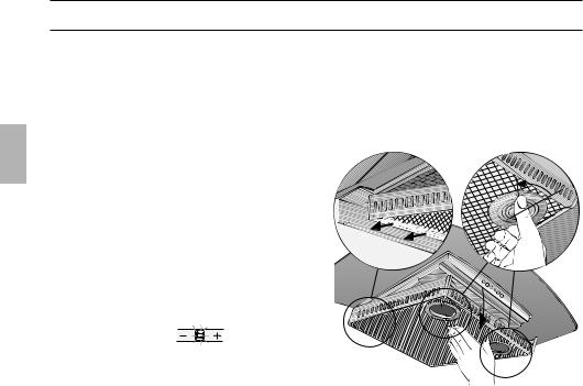
Ausund Einbauen des Metall-Fettfilters:
Achtung: Die Halogenlampen müssen ausgeschaltet und abgekühlt sein.
1.Drehen Sie die beiden Riegel am Fettfilter und klappen Sie den Fettfilter ab.
2.Reinigen Sie den Fettfilter.
3.Setzen Sie den gereinigten Fettfilter wieder ein.
4.Löschen Sie die Anzeige #.
Drücken Sie das Symbol 0.
6
Filter und Wartung
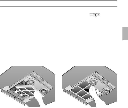
Aktivkohlefilter:
Zum Binden der Geruchsstoffe beim Umluftbetrieb.
Einbauen:
Achtung: Die Halogenlampen müssen ausgeschaltet und abgekühlt sein.
1.Bauen Sie den Fettfilter aus
(siehe Ausund Einbauen der MetallFettfilter).
2.Setzen Sie den Aktivkohlefilter ein.
3.Rasten Sie die Lasche vorne ein.
4.Bauen Sie den Fettfilter ein
(siehe Ausund Einbauen des MetallFettfilters).
5.Löschen Sie die Anzeige ã.
Drücken Sie das Symbol 0.
Sättigungsanzeige:
Bei Sättigung des Aktivkohlefilters
ertönt nach dem Ausschalten des Lüfters für 10 Sekunden ein Signal und die Anzeige ã leuchtet. Spätestens dann sollte der Aktivkohlefilter gewechselt werden.
Ausbauen:
Achtung: Die Halogenlampen müssen ausgeschaltet und abgekühlt sein.
1.Bauen Sie den Fettfilter aus.
2.Drücken Sie die Lasche vorne ein und nehmen Sie den Aktivkohlefilter nach unten ab.
3. Bauen Sie den Fettfilter ein.
Wechsel des Aktivkohlefilters:
Der Aktivkohlefilter ist im Fachhandel erhältlich (siehe Sonderzubehör).
Nur Originalfilter verwenden.
Dadurch wird die optimale Funktion gewährleistet.
Entsorgung des alten Aktivkohlefilters:
Aktivkohlefilter enthalten keine Schadstoffe. Sie können z. B. als Restmüll entsorgt werden.
7
Reinigen und Pflegen
Dunstabzugshaube durch Ziehen des Netzsteckers bzw. Ausschalten der Sicherung stromlos machen.
Beim Reinigen der Fettfilter die zugänglichen Gehäuseteile von abgelagertem Fett reinigen.
Dadurch wird der Brandgefahr vorgebeugt und die optimale Funktion bleibt erhalten.
Zum Reinigen der Dunstabzugshaube heiße Spüllauge oder mildes Fensterputzmittel verwenden.
Kratzen Sie angetrocknete Verschmutzung nicht ab, sondern weichen Sie diese mit einem feuchten Tuch auf.
Keine scheuernden Mittel oder kratzende Schwämme verwenden.
Hinweis: Alkohol (Spiritus) nicht auf Kunststoffflächen anwenden, es könnten matte Stellen entstehen.
Vorsicht! Küche ausreichend belüften, keine offene Flamme.
Die Bedientasten nur mit milder Spüllauge und einem weichen, feuchten Tuch reinigen.
Keinen Edelstahlreiniger für die Bedientasten verwenden.
Edelstahloberflächen:
Verwenden Sie einen milden nicht scheuernden Edelstahlreiniger.
Reinigen Sie nur in Schliffrichtung.
Edelstahloberflächen nicht mit kratzenden Schwämmen und nicht mit sand-, soda-, säureoder chloridhaltigen Putzmitteln reinigen!
Aluminium-, Lackund Kunststoffoberflächen:
Verwenden Sie ein weiches, fusselfreies Fensteroder Microfasertuch.
Keine trockenen Tücher verwenden.
Verwenden Sie ein mildes Fensterreinigungsmittel.
Keine aggressiven, säureoder laugenhaltigen Reiniger verwenden.
Keine Scheuermittel verwenden.
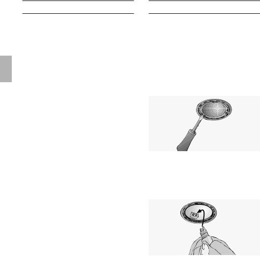
Auswechseln der Lampen
1.Schalten Sie die Dunstabzugshaube aus und machen Sie durch Ziehen des Netzsteckers oder Ausschalten der Sicherung die Dunstabzugshaube stromlos.
Die Halogenbirnen werden bei Betrieb sehr heiß. Auch einige Zeit nach dem Ausschalten besteht noch Verbrennungsgefahr.
2.Nehmen Sie den Lampenring mit einem Schraubenzieher oder ähnlichem ab.
3.Tauschen Sie die Halogenbirne aus (handelsübliche Halogenbirne, 12 Volt, max. 20 Watt, Sockel G4).
Achtung: Steckfassung.
Zum Anfassen der Birne ein sauberes Tuch verwenden.
4.Rasten Sie den Lampenring wieder ein.
5.Stellen Sie durch Einstecken des Netzsteckers oder durch Einschalten der Sicherung die Stromversorgung wieder her.
Hinweis: Sollte die Beleuchtung nicht funktionieren, kontrollieren Sie, ob die Lampen richtig eingesteckt sind.
8
Einstellung der Sättigungsanzeige
Sollte die Umstellung der Betriebsart (Abluft/Umluftbetrieb) notwendig sein, muss auch die Sättigungsanzeige für die Filter entsprechend umgestellt werden (siehe Montageanweisung).
Störungen
Wenn in der Anzeige ein # oder ã erscheint:
Siehe Abschnitt „Filter und Wartung”.
Wenn sich die Dunstabzugshaube nicht bedienen lässt:
Für ca. 1 Minute die Dunstabzugshaube durch Ziehen des Netzsteckers bzw. Ausschalten der Sicherung stromlos machen.
Danach neu einschalten.
Bei eventuellen Rückfragen oder Störungen, Kundendienst anrufen.
(Siehe Kundendienststellenverzeichnis). Bei Anruf bitte angeben:
E-Nr. FD
Tragen Sie die Nummern in obige Felder ein. Die Nummern sind auf dem Typenschild, nach Abnahme der Fettfilter, im Innenraum der Dunstabzugshaube zu finden.
9
Montageanweisung:
Wichtige Hinweise
Altgeräte sind kein wertloser Abfall. Durch umweltgerechte Entsorgung können wertvolle Rohstoffe wiedergewonnen werden.
Bevor Sie das Altgerät entsorgen, machen Sie es unbrauchbar.
Ihr neues Gerät wurde auf dem Weg zu Ihnen durch die Verpackung geschützt. Alle eingesetzten Materialien sind umweltverträglich und wieder verwertbar. Bitte helfen Sie mit und entsorgen Sie die Verpackung umweltgerecht.
Über aktuelle Entsorgungswege informieren Sie sich bitte bei Ihrem Fachhändler oder bei Ihrer Gemeindeverwaltung.
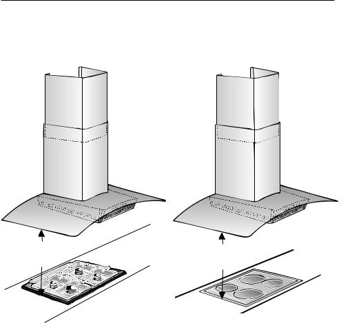
Die Dunstabzugshaube ist für Abluftund Umluftbetrieb verwendbar.
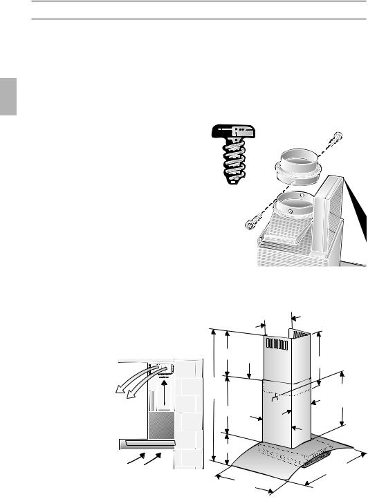
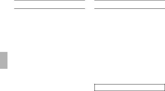
Die Dunstabzugshaube immer über der Mitte der Kochstellen anbringen.
Mindestabstand zwischen Elektrokochstellen und Unterkante der Dunstab-
zugshaube: |
550 mm, Abb. 1. |
Über Gas-Kochstellen ist bei der Montage ein Mindestabstand von 650 mm einzuhalten, Abb. 1.
Gas-Kochstellen dürfen nur mit aufgesetztem Kochgeschirr benutzt werden.
Gas-Kochmulden / Gas-Herde:
Die während des Betriebes entstehende Wärmebelastung aller Kochstellen darf
8,0 kW nicht überschreiten, unabhängig von der installierten Nennleistung.
Ausnahme:
Kurzzeitig (max. 15 Minuten) können die Kochstellen mit einer Wärmebelastung bis zu 11,3 kW betrieben werden, wenn mindestens die Lüfterstufe 2 ständig eingeschaltet ist. (Sonst besteht Verbrennungsgefahr bei Berührung der Gehäuseoberflächen).
Herde für feste Brennstoffe
Es gelten sinngemäß die maximalen Nennwärmebelastungen und der Mindestabstand wie bei Gas-Herden.
Zusätzliche Hinweise bei Gas-Koch- geräten:
Bei der Montage von Gaskochstellen sind die national einschlägigen gesetzlichen Bestimmungen (z. B. in Deutschland: Technische Regeln Gasinstallation TRGI) zu beachten.
Es müssen die jeweils gültigen Einbauvorschriften und die Einbauhinweise der Gas-Gerätehersteller beachtet werden.
Die Dunstabzugshaube darf nur an einer Seite neben einem Hochschrank oder einer hohen Wand eingebaut werden. Abstand mind. 50 mm.
Über einer Feuerstätte für feste Brennstoffe, von der eine Brandgefahr (z. B. Funkenflug) ausgehen kann, ist die
Montage der Dunstabzugshaube nur dann zulässig, wenn die Feuerstätte eine geschlossene nicht abnehmbare Abdeckung hat und die länderspezifischen Vorschriften eingehalten werden.
Diese Einschränkung gilt nicht für GasHerde und Gas-Mulden.
Je kleiner der Abstand zwischen Dunstabzugshaube und Kochstellen desto größer ist die Möglichkeit, dass sich durch aufsteigenden Wasserdampf unten an der Dunstabzugshaube Tropfen bilden können.
10
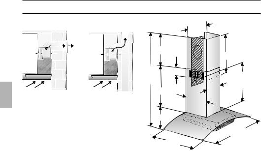
Vor der Montage
Abluftbetrieb
120 |
120 |
|
150 |
||
150 |
||
|
Die Abluft wird über einen Lüftungsschacht nach oben, oder direkt durch die Außenwand ins Freie geleitet.
DDie Abluft darf weder in einen in Betrieb befindlichen Rauchoder Abgaskamin noch in einen Schacht, welcher der Entlüftung von Aufstellungsräumen von Feuerstätten dient, abgegeben werden.
Bei der Ableitung von Abluft sind die behördlichen und gesetzlichen Vorschriften (z. B. Landesbauordnungen) zu beachten.
Bei Abführung der Luft in nicht in Betrieb befindliche Rauchoder Abgaskamine ist die Zustimmung des zuständigen Schornsteinfegermeisters einzuholen.
DBei Abluftbetrieb der Dunstabzugshaube und gleichzeitigem Betrieb schornsteinabhängiger Feuerungen (wie z. B. Gas-, Öloder Kohleheizgeräte, Durchlauferhitzer, Warmwasserbereiter) muss für ausreichend Zuluft gesorgt werden, die von der Feuerstätte zur Verbrennung benötigt wird.
Ein gefahrloser Betrieb ist möglich, wenn der Unterdruck im Aufstellraum der Feuerstätte von 4 Pa (0,04 mbar) nicht überschritten wird.
|
0 |
|
|
30 |
|
mind.95 |
||
|
620 |
|
705- |
130 |
|
1100 |
mind. |
|
|
500 |
|
535 |
245 |
|
280 |
||
|
||
75 |
|
|
|
900 |
|
|
500 |
|
Dies kann erreicht werden, wenn durch nicht verschließbare Öffnungen, z. B. in Türen, Fenstern und in Verbindung mit Zuluft-/Abluftmauerkasten oder durch andere techn. Maßnahmen, wie gegenseitige Verriegelung o. ä., die Verbrennungsluft nachströmen kann.
Bei nicht ausreichender Zuluft besteht Vergiftungsgefahr durch zurückgesaugte Verbrennungsgase.
Ein Zuluft-/Abluftmauerkasten allein stellt die Einhaltung des Grenzwertes nicht sicher.
Anmerkung: Bei der Beurteilung muss immer der gesamte Lüftungsverbund der Wohnung beachtet werden. Bei Betrieb von Kochgeräten, z. B. Kochmulde und Gasherd wird diese Regel nicht angewendet.
Wenn die Dunstabzugshaube im Umluftbetrieb – mit Aktivkohlefilter – verwendet wird, ist der Betrieb ohne Einschränkung möglich.
Wird die Abluft durch die Außenwand geleitet, sollte ein Teleskop-Mauerkasten verwendet werden.
11
Vor der Montage
Optimale Leistung der Dunstabzugshaube:
Kurzes, glattes Abluftrohr.
Möglichst wenig Rohrbögen.
Möglichst große Rohrdurchmesser und große Rohrbögen.
Der Einsatz von langen, rauhen Abluftrohren, vielen Rohrbögen oder kleineren Rohrdurchmessern führt zu einer Abweichung von der optimalen Luftleistung und gleichzeitig zu einer Geräuscherhöhung.
Rundrohre:
Wir empfehlen
Innendurchmesser 150 mm, jedoch mind. 120 mm.
Flachkanäle müssen einen gleichwertigen Innenquerschnitt wie Rundrohre haben.
Sie sollten keine scharfen Umlenkungen haben.
l 120 mm ca. 113 cm2 l 150 mm ca. 177 cm2
Bei abweichenden Rohrdurchmessern: Dichtstreifen einsetzen.
Bei Abluftbetrieb für ausreichend Zuluft sorgen.
Umluftbetrieb
Mit Aktivkohlefilter, wenn keine Möglichkeit für Abluftbetrieb vorhanden ist.
Das komplette Montage-Set können Sie beim Fachhandel erwerben.
Die entsprechenden Zubehör-Nummern finden Sie am Ende dieser Gebrauchsanweisung.
Anschluss Abluftrohr l 150 mm:
Abluftrohr direkt am Luftstutzen befestigen.
Anschluss Abluftrohr l 120 mm:
Reduzierstutzen an den Luftstutzen schrauben und daran das Abluftrohr befestigen.
|
0 |
|
|
30 |
|
mind. 130 |
620 |
|
|
||
740- |
mind. |
|
1170 |
||
|
500 |
|
535 |
245 |
|
280 |
||
|
||
75 |
|
|
|
900 |
|
500 |
|
12

Vor der Montage |
|
Elektrischer Anschluss |
Vorbereiten der Wand
Die Wand muss eben und senkrecht sein.
Für festen Halt der Dübel ist zu sorgen.
Gewicht in kg:
|
|
|
|
|
|
|
Abluft |
|
|
Umluft |
|
|
|
|
|
||
|
|
|
|
|
|
|
21,5 |
|
|
22,5 |
|
|
|
|
|
|
|
Konstruktionsänderungen im Rahmen der technischen Entwicklung bleiben vorenthalten.
Die Dunstabzugshaube darf nur an eine vorschriftsmäßig installierte Schutzkontaktsteckdose angeschlossen werden.
Die Schutzkontaktsteckdose möglichst direkt hinter der Kaminverblendung anbringen.
Elektrische Daten:
Sie sind auf dem Typenschild nach Abnahme der Filterrahmen – im Innenraum des Gerätes – zu finden.
Bei Reparaturen die Dunstabzugshaube generell stromlos machen.
Länge der Anschlussleitung: 1,30 m. Bei erforderlichem Festanschluss:
Die Dunstabzugshaube darf in jedem Fall nur durch einen beim zuständigen Elektrizitäts-Versorgungsunternehmen eingetragenen Elektro-Installateur angeschlossen werden.
Installationsseitig ist eine Trennvorrichtung vorzusehen. Als Trennvorrichtung gelten Schalter mit einer Kontaktöffnung von mehr als 3 mm und allpoliger Abschaltung. Dazu gehören LS-Schalter und Schütze.
Diese Dunstabzugshaube entspricht den EG-Funkentstörbestimmungen.
Umstellen Abluft – Umluftbetrieb
Umstellung der elektronischen Steuerung auf Umluftbetrieb:
Serienmäßige Einstellung ist Abluftbetrieb.
Die Dunstabzugshaube muss angeschlossen und ausgeschaltet sein.
1.Taste 0 drücken und halten.
2.Während die Anzeige { leuchtet
zusätzlich die Taste  drücken, bis die Anzeige ã leuchtet. Danach die Tasten loslassen.
Die Anzeige ã erlischt nach kurzer Zeit. Die elektronische Steuerung ist auf Umluftbetrieb eingestellt.
Durch Wiederholen der Schritte 1 und 2
wird die elektronische Steuerung wieder auf Abluftbetrieb umgestellt (Anzeige #).
13
Einbauen
Die Dunstabzugshaube ist für die Montage an die Küchenwand vorgesehen.
1. Fettfilter abnehmen
(siehe Gebrauchsanweisung).
2. Von der Decke bis zur Unterkante der Dunstabzugshaube eine Mittellinie an die Wand anzeichnen.
3. Mit Hilfe der Schablone Positionen für die Schrauben an der Wand anreißen und zum leichteren Einhängen die Kontur des Einhängebereiches anzeichnen.
Auf Mindestabstand Kochstelle – Dunstabzugshaube von 550 mm bei Elektro-Kochstellen bzw. 650 mm bei GasKochstellen achten. Der untere Rand der Schablone entspricht dem unteren Rand der Dunstabzugshaube (Glasschirm).
4.3 Löcher für die Dunstabzugshaube und
2 Löcher für die Kaminverblendung
l 8 mm bohren und Dübel wandbündig eindrücken.
23
216

 172
172 
486
45
mind 550 Elektro mind 650 Gas
Hinweis: Achten Sie auf eventuell zu montierende Sonderzubehörteile.
5.Den oberen und die zwei unteren Haltewinkel anschrauben.
6.Dunstabzugshaube einhängen. Höhe und waagerechte Lage mit den Verstellschrauben ausrichten.
Der Glasschirm darf nicht an der Wand anschlagen.
14

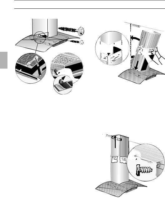
Einbauen
07. Untere Schraube (Sechskant-
schraube) eindrehen.


 2.
2. 


 1.
1. 
Entsteht beim Festschrauben ein Druck auf den Glasschirm, kann es zu Glasbruch führen.
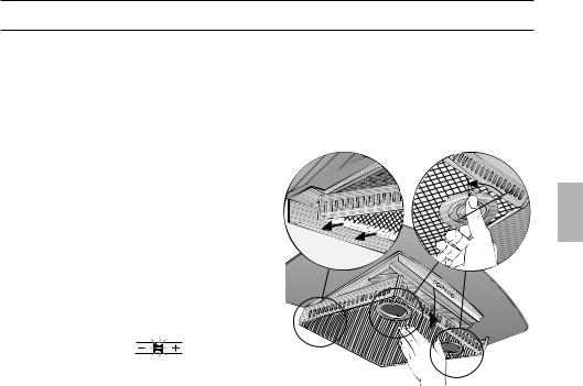
08. Je eine Abdeckfolie über die Löcher der
2 unteren Befestigungsschrauben auf das Schutzgitter kleben.
09. Rohrverbindung herstellen.
10.Elektrische Verbindung herstellen.
11.Schutzfolie an den beiden
Kaminverblendungen abziehen.
Vermeiden Sie Beschädigungen der empfindlichen Oberflächen.
12.Die obere Kaminverblendung (Schlitze nach unten) in die untere Kaminverblendung einschieben.
 3.
3.
 1.
1.


 2.
2.

Vermeiden Sie Kratzer beim Ineinanderschieben, in dem Sie z. B. die Montageschablone als Schutz über die Kante der unteren Kaminverblendung legen.
13.Die komplette Kaminverblendung in den Glasschirm schräg einsetzen und nach hinten schwenken.
14.Die obere Kaminverblendung vorsichtig nach oben ausziehen und mit 2 Schrauben seitlich an den Haltewinkel schrauben.
15.Fettfilter wieder einsetzen (siehe Gebrauchsanweisung).
15
Instructions for use:
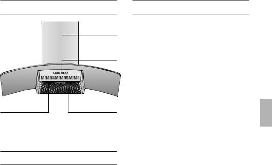
Appliance description
|
Chimney |
|
panelling |
|
Light / fan |
|
switches |
Lighting |
Filter grille |
Operating modes
Exhaust-air mode:
The extractor-hood fan extracts the kitchen vapours and conveys them through the grease filter into the atmosphere.
The grease filter absorbs the solid particles in the kitchen vapours.
The kitchen is kept almost free of grease and odours.
DWhen the extractor hood is operated in exhaust-air mode simultaneously with a different burner which also makes use of the same chimney (such as gas, oil or coal-fired heaters, continuous-flow heaters, hot-water boilers) care must be taken to ensure that there is an adequate supply of fresh air which will be needed by the burner for combustion.
Safe operation is possible provided that the underpressure in the room where the burner is installed does not exceed 4 Pa (0.04 mbar).
Operating modes
This can be achieved if combustion air can flow through non-lockable openings, e.g. in doors, windows and via the air- intake/exhaust-air wall box or by other technical measures, such as reciprocal interlocking, etc.
If the air intake is inadequate, there is a risk of poisoning from combustion gases which are drawn back into the room.
An air-intake/exhaust-air wall box by itself is no guarantee that the limiting value will not be exceeded.
Note: When assessing the overall requirement, the combined ventilation system for the entire household must be taken into consideration. This rule does not apply to the use of cooking appliances, such as hobs and ovens.
Unrestricted operation is possible if the extractor hood is used in recirculating mode
– with activated carbon filter.
Circulating-air mode:
An activated carbon filter must be fitted for this operating mode (see Filters and
maintenance).
The complete installation set and replacement filters can be obtained from specialist outlets.
The corresponding accessory numbers can be found at the end of these operating instructions.
The extractor-hood fan extracts the kitchen vapours which are purified in the grease filter and activated carbon filter and then conveyed back into the kitchen.
The grease filter absorbs the grease particles in the kitchen vapours.
The activated carbon filter binds the odorous substances.
16
Before using for the first time
Important notes:
The Instructions for Use apply to several versions of this appliance. Accordingly, you may find descriptions of individual features that do not apply to your specific appliance.
This extractor hood complies with all relevant safety regulations.
Repairs should only be carried out by qualified specialists.
Improperly executed repairs can give rise to significant hazards for the user.
Do not use the appliance if it is damaged in any way
The appliance is not intended for use by young children or infirmed persons without supervision.
Young children should be supervised to ensure they do not play with the appliance.
The appliance should only be connected up to the mains and taken into use by a qualified specialist.
Dispose of packaging materials properly (see Installation instructions).
Light bulbs must always be fitted when the extractor hood is in use.
Defective bulbs should be replaced immediately to prevent the remaining bulbs from overloading.
Never operate the extractor hood without a grease filter.
Overheated fat or oil can easily catch
fire.
If you are cooking with fat or oil, e.g. chips, etc., never leave the cooker unattended.
Before using your new appliance, please read these Instructions for Use carefully. They contain important information concerning your personal safety as well as on use and care of the appliance.
Please keep the operating and installation instructions in a safe place; this important documentation may also be of use to a possible subsequent owner.
Do not flambé food directly under the extractor hood.
!Risk of grease filter catching fire due to flames.
Restrictions apply to the use of the extractor hood over a solid-fuel burner (coal, wood, etc.). (See Installation instructions).
Gas hobs / gas cookers
Always use gas hobs in a proper and safe manner.
Important:
The flames from the gas hob must always be covered by pots or pans.
The intense heat generated by the gas
!flames could cause damage to the extractor hood.
The heat load of all the hotplates which is produced during operation must not exceed 8.0 kW, irrespective of the installed nominal output.
Exception:
The hotplates may be operated briefly (max. 15 minutes) at a heat load up to 11.3 kW if at least fan setting 2 has been permanently switched on.
(Otherwise, there is a risk of burns if the housing surfaces are touched).
17
Operating procedure
The most effective method of removing vapours produced during cooking is to:
Switch the ventilator ON
as soon as you begin cooking.
Switch the ventilator OFF
a few minutes after you have finished cooking.
|
|
|
|
|
|
|
|
|
|
|
|
|
|
|
|
|
|
|
|
|
|
|
|
|
|
|
|
|
|
|
|
|
|
|
|
|
|
|
|
|
|
|
|
|
|
|
|
|
|
|
|
|
|
|
|
|
|
|
|
|
|
|
|
|
|
Light |
|
|
|
Display for |
Fan follow- |
||||||||
|
|
|
|
|
|
|
|
fan setting |
on |
||||||
|
|
|
|
|
|
|
|
|
|
|
|
|
|||
|
|
Fan OFF |
Reduce fan speed |
Fan ON and |
|||||||||||
|
|
|
|
|
|
|
|
|
|
|
|
increase |
|||
|
|
|
|
|
|
|
|
|
|
|
|
speed |
|||
Acoustic signal:
When a button is pressed, this is verified by an acoustic signal.
Switching off the acoustic signal:
Simultaneously press buttons 0 and + until a signal is emitted after approx. 3 seconds.
Switching on the acoustic signal:
Repeat the process.
Switching the fan ON
Press the + button.
Setting the required fan speed:
Press the + button.
The fan speed is increased by one step.
Press the – button.
The fan speed is reduced by one step.
Switching the fan OFF:
Press the 0 button.
The displayed { goes out shortly afterwards.
Or:
Keep pressing the – button until the fan
switches off.
The displayed { goes out shortly afterwards.
Intensive setting:
Maximum power is obtained at the intensive setting. It is only required for short intervals.
Keep pressing the + button until a ç appears in the display.
If the intensive setting is not cancelled by
hand, the fan will automatically switch back to step } after 10 minutes.
Fan follow-on:
Press the  button.
The fan continues to run at step | for 10 minutes, and at the same time a dot flashes in the display. After this period the fan switches off automatically.
Lighting:
Briefly press the a button to switch the light on and off.
The light can be switched on at any time, even though the fan is switched off.
Adjusting the brightness:
Hold down the a button until the desired brightness is obtained.
Switching on the light automatically, e.g. via a timer:
Fan and light must be switched off.
Switching on:
Simultaneously press the – and ! buttons.
After approx. 3 seconds the light switches on to acknowledge the setting.
Switching off:
Repeat the process with the light switched on.
After approx. 3 seconds the light switches off to acknowledge the setting.
18
Filters and maintenance
Grease filters:
Metal filters are used to trap the greasy element of the vapours that develop during cooking.
The filter mats are made from noncombustible metal.
Caution:
As the filter becomes more and more saturated with grease, not only does the risk of it catching fire increase but the efficiency of the extractor hood can also be adversely affected.
Important:
By cleaning the metal grease filters at appropriate intervals, the possibility of them catching fire as a result of a build-up of heat such as occurs when deep-fat frying or roasting is taking place, is reduced.
Saturation indicator:
When the grease filters reach saturation point, an acoustic signal is sounded for 10 seconds after the fan has switched off, and an # appears in the display. The grease filters should be cleaned straight away.
Cleaning the metal grease filters:
The filters can be cleaned in a dishwasher. It is however possible that they will become slightly discoloured.
Important:
Metal filters that are saturated with grease should not be washed together with other dishes etc.
When cleaning the filters by hand, soak them in hot soapy water first of all. Then brush the filters clean, rinse them
thoroughly and leave the water to drain off.
Removing and inserting the metal grease filters:
Warning: The halogen bulbs must be switched off and cool.
1.Rotate the two catches on the grease filter and remove the grease filter.
2.Clean the grease filter.
3.Re-insert the clean grease filter.
4.Cancel the # in the display.
Press the 0 button.
19

Filters and maintenance
Activated carbon filter:
For neutralizing odours in recirculating mode.
Inserting the filter:
Warning: The halogen bulbs must be switched off and cool.
1.Remove the metal filters (see "Removing and inserting the metal grease filters").
2.Insert the activated carbon filter.
3.Engage the lug at the front.
4.Insert the metal grease filters (see "Removing and inserting the metal grease filters").
5.Cancel the ã in the display.
Press the 0 button.
Saturation indicator:
When the activated carbon filter reaches saturation point, an acoustic signal is sounded for 10 seconds after the fan has switched off, and a ã appears in the display. The activated carbon filter should be replaced straight away.
Removing the filter:
Warning: The halogen bulbs must be switched off and cool.
1.Remove the metal filters.
2.Press in the lug at the front and remove the activated carbon filter.
3. Insert the metal grease filters.
Replacing the activated carbon filter:
A replacement filter can be obtained from any authorized dealer (see optional accessories).
Use original filters only.
By doing so you will obtain maximum performance from your extractor hood.
Disposing of the old activated carbon filter:
There are no pollutants in the activated carbon filters. They can therefore be disposed of as part of your normal domestic refuse.
20
Cleaning and care
Disconnect the extractor hood from the electricity supply by pulling out the mains plug or switching it off at the fuse box.
At the same time as you clean the grease filters, clean off any grease from all accessible parts of the housing. This significantly reduces the fire hazard and ensures that the extractor hood performs as effectively as possible.
Use a hot detergent solution or a mild window cleaner to clean the canopy of the extractor hood.
Do not scrape off any dirt that has dried on but loosen it up with a damp cloth.
Do not use abrasive cleaning agents or sponges that could cause scratches.
Note: Do not use alcohol (spirit) on plastic parts, otherwise the surface may become matt in appearance.
Caution: Ensure that the kitchen is adequately ventilated. Avoid naked flames!
Clean the operating buttons with a mild soapy solution and a soft, damp cloth only. Do not use stainless-steel cleaner to clean the operating buttons.
Stainless steel surfaces:
Use a mild non-abrasive stainless steel cleaner.
Clean the surface in the same direction as it has been ground and polished.
Do not use any of the following to clean stainless steel surfaces: abrasive sponges, cleaning agents containing sand, soda, acid or chloride!
Aluminium, painted and plastic surfaces:
Use a soft, non-linting window cloth or micro-fibre cloth.
Do not use dry cloths.
Use a mild window cleaning agent.
Do not use aggressive, acidic or caustic cleaners.
Do not use abrasive agents.
Replacing the light bulbs
1.Switch off the extractor hood and pull out the mains plug or switch off the electricity supply at the fuse box.
When switched on, the halogen bulbs become very hot. Even for some time after the bulbs have been switched off there is still a risk of burns.
2.Remove the bulb ring with a screwdriver or similar tool.
3.Replace the halogen light bulb (conventional halogen bulb, 12 Volt, max. 20 Watt, G4 cap).
Caution: Refer for plug-in lampholder. Take hold of the bulb with a clean cloth.
4.Re-insert the bulb ring.
5.Plug the appliance into the mains or switch it on at the fuse box.
Note: If the light does not function, check that the bulbs have been inserted correctly.
21
Setting the saturation indicator
If it becomes necessary to change the operating mode (exhaust-air/recirculating mode), the saturation indicator for the filters must also be altered (see Installation Instructions).
If you encounter a problem
If an # or ã appears in the display:
See "Filters and maintenance" Section.
If is not possible to operate the extractor hood:
Disconnect the extractor hood from the mains electricity supply by pulling out the plug or switching it off at the main fuse box.
Wait for approx. 1 minute and then switch it on again.
If you have any questions or if a fault occurs, please call Customer Service.
(See list of Customer Service representatives).
When you call, please quote the following:
E-Nr. FD
Enter the relevant numbers into the box above. The E-Nr. (product no.) and FD (production date) are shown on the nameplate which can be seen inside the extractor hood after the filter frame has been detached.
22
Installation Instructions:
Important information
Old appliances are not worthless rubbish. If they are disposed of in an environment-friendly manner, valuable raw materials can be recovered for use again. Before you dispose of an old appliance, make sure that it has been rendered inoperative.
Your new appliance was protected on its way to you by the packaging. None of the materials cause pollution to the environment and all can be recycled for use again. Please help to protect the environment and dispose of the packaging in an environment-friendly manner.
You can obtain information about the best method disposing of old appliances and packaging from your dealer or local municipal council.
The extractor hood can be used in either exhaust-air or recirculating mode.
Always mount the extractor hood over the centre of the hob.
Minimum distance between electric hob and bottom edge of extractor hood:
550 mm, Fig. 1.
Additional notes concerning gas cookers:
When installing gas hotplates, comply with the relevant national statutory regulations (e.g. in Germany: Technische Regeln Gasinstallation TRGI).
The relevant regulations and installation notes provided by the manufacturer of the gas cooker must be observed in all cases.
The extractor hood may be installed next to only one full-height cupboard or high wall. Gap to be at least 50 mm.
During installation observe a minimum distance of 650 mm above the gas hotplates. Fig. 1.
Gas hotplates may only be used when cooking utensils have been placed on them.
Gas hobs / gas cookers:
The heat load of all the hotplates which is produced during operation must not exceed 8.0 kW, irrespective of the installed nominal output.
Exception:
The hotplates may be operated briefly (max. 15 minutes) at a heat load up to 11.3 kW if at least fan setting 2 has been permanently switched on. (Otherwise, there is a risk of burns if the housing surfaces are touched).
Solid-fuel cookers
The maximum nominal heat loads and the minimum distance are the same as for gas cookers.
Installation of the extractor hood over a solid-fuel burner which could constitute a potential fire hazard (e.g. due to flying sparks) is only permitted if the burner is equipped with an enclosed, nonremovable cover and all country-specific regulations are observed. This restriction does not apply to gas cookers and gas hobs.
The smaller the gap between extractor hood and hob, the greater the likelihood that rising steam will cause condensation to form on the hood.
23
Prior to installation
Exhaust-air mode
120 |
120 |
|
150 |
||
150 |
||
|
The exhaust air is discharged upwards through a ventilation shaft or directly through the outside wall into the open.
DExhaust air should neither be directed into a smoke or exhaust flue that is currently used for other purposes, nor into a shaft that is used for ventilating rooms in which stoves or fireplaces are also located.
Exhaust air may be discharged in accordance with official and statutory regulations only (e.g. national building regulations).
Local authority regulations must be observed when discharging air into smoke or exhaust flues that are not otherwise in use.
DWhen the extractor hood is operated in exhaust-air mode simultaneously with a different burner which also makes use of the same chimney (such as gas, oil or coal-fired heaters, continuous-flow heaters, hot-water boilers) care must be taken to ensure that there is an adequate supply of fresh air which will be needed by the burner for combustion.
Safe operation is possible provided that the underpressure in the room where the burner is installed does not exceed 4 Pa (0.04 mbar).
|
0 |
|
|
30 |
|
mind.95 |
||
|
620 |
|
705- |
130 |
|
1100 |
mind. |
|
|
500 |
|
535 |
245 |
|
280 |
||
|
||
75 |
|
|
|
900 |
|
|
500 |
|
This can be achieved if combustion air can flow through non-lockable openings, e.g. in doors, windows and via the air- intake/exhaust-air wall box or by other technical measures, such as reciprocal interlocking, etc.
If the air intake is inadequate, there is a risk of poisoning from combustion gases which are drawn back into the room.
An air-intake/exhaust-air wall box by itself is no guarantee that the limiting value will not be exceeded.
Note: When assessing the overall requirement, the combined ventilation system for the entire household must be taken into consideration. This rule does not apply to the use of cooking appliances, such as hobs and ovens.
Unrestricted operation is possible if the extractor hood is used in recirculating mode – with activated carbon filter.
24
Prior to installation
For optimum extractor hood efficiency:
Short, smooth air exhaust pipe.
As few bends in the pipe as possible.
Diameter of pipe to be as large as possible and no tight bends in pipe.
If long, rough exhaust-air pipes, many pipe bends or smaller pipe diameters are used, the air extraction rate will no longer be at an optimum level and there will be an increase in noise.
Round pipes:
We recommend
Internal diameter: 150 mm (at least 120 mm).
Flat ducts must have an internal crosssection that equates to that of round pipes.
There should be no sharp bends. l 120 mm approx. 113 cm2
l 150 mm approx. 177 cm2
If pipes have different diameters:
Insert sealing strip.
For exhaust-air mode, ensure that there is an adequate supply of fresh air.
Circulating-air mode
With activated carbon filter if exhaust-air mode is not possible.
The complete installation set can be obtained from specialist outlets.
The corresponding accessory numbers can be found at the end of these operating instructions.
Connecting a l 150 mm exhaust-air pipe:
Mount the pipe directly onto the air outlet on the hood.
Connecting a l 120 mm exhaust-air pipe:
Screw a reducing adapter onto the air outlet on the hood and then connect the exhaust-air pipe.
|
0 |
|
|
30 |
|
mind. 130 |
620 |
|
|
||
740- |
mind. |
|
1170 |
||
|
500 |
|
535 |
245 |
|
280 |
||
|
||
75 |
|
|
|
900 |
|
500 |
|
25
Prior to installation
Preparing the wall
The wall must be flat and perpendicular.
Ensure that the wall is capable of providing a firm hold for mounting screws and plugs.
Weight in kg:
|
|
|
|
|
|
|
Exhaust air |
|
|
Recirculating air |
|
|
|
|
|
|
|
|
|
|
|
|
|
|
21,5 |
|
|
22,5 |
|
|
|
|
|
|
|
We reserve the right to construction changes within the context of technical development.
Changing over from exhaustair to recirculating mode
Changing the electronic control system to recirculating mode:
The standard factory setting is for operation in exhaust-air mode.
To change the mode, the extractor hood must have been connected up and should be switched off.
1.Press and hold the 0 button.
2.While { is displayed, press the  button until ã is displayed. When this has taken place, release the buttons.
ã goes out shortly afterwards.
The electronic control system will then have been set to recirculating mode.
By repeating steps 1 and 2, you can
change the electronic control system back to exhaust-air mode (# in display).
Electrical connection
WARNING: THIS APPLIANCE MUST BE EARTHED
IMPORTANT: Fitting a Different Plug:
The wires in the mains lead are coloured in accordance with the following code:
Green and Yellow |
– |
Earth |
Blue |
– |
Neutral |
Brown |
– |
Live |
If you fit your own plug, the colours of these wires may not correspond with the identifying marks on the plug terminals.
This is what you have to do:
1.Connect the green and yellow (Earth) wire to the terminal in the plug marked ‘E’ or with the symbol (  ), or coloured green or green and yellow.
2.Connect the blue (Neutral) wire to the terminal in the plug marked ‘N’ or coloured black.
3.Connect the brown (Live) wire to the terminal marked ‘L’, or coloured red.
The extractor hood should only be connected to an earthed socket that has been installed according to relevant regulations.
If possible, site the earthed socket directly behind the chimney panelling.
Electrical data:
Are to be found on the name plate inside the appliance after removal of the filter frame.
Before undertaking any repairs, always disconnect the extractor hood from the electricity supply.
Length of the connecting cable: 1.30 m.
If it is necessary to wire the extractor hood directly into the mains:
The extractor hood should only be connected to the electricity supply by a properly qualified electrician.
A separator must be installed in the household circuit. A suitable separator is a switch that has a contact gap of more than 3 mm and interrupts all poles. Such devices include circuit breakers and contactors.
This extractor hood corresponds to EC regulations concerning RF interference suppression.
26
Installation
This extractor hood is intended to be mounted onto the kitchen wall.
1. Remove the grease filter
(refer to Operating Instructions).
2. Draw a line on the wall from the ceiling to the lower edge of the hood at the centre of the location where the hood is going to be mounted.
3. Use the template to mark the points on the wall where the screws will be mounted. In order to make it easier to hook the hood onto the screws, draw the outline of the area where the hood will be attached.
Ensure that the minimum distance between the hob and the extractor hood is maintained – 550 mm for an electric hob and 650 mm for a gas hob. The bottom edge of the template corresponds to the lower edge of the extractor hood (glass screen).
4.Drill 3 x l 8 mm holes for the extractor hood and 2 x l 8 mm holes for the chimney panelling. Insert plugs into the holes so that they are flush with the wall.
23
216

 172
172 
486
45
mind 550 Elektro mind 650 Gas
Note: Take into account any special accessories that are going to be fitted.
5.Screw on the upper and the two lower fixing brackets.
6.Attach the extractor hood.
Adjust the height and align horizontally with the adjusting screws.
The glass screen must not touch the wall.
27
Installation
07. Screw in the lower bolt (hex bolt).


 2.
2. 


 1.
1. 
If any pressure is exerted on the glass screen when tightening the screws it could lead to glass breakage.
08. Stick protective film over the holes of the 2 lower mounting bolts in the protective grid.
09. Connect up the air outlet pipe.
10.Connect the hood to the electricity supply.
11.Remove the protective film from the
two flue ducts.
Avoid damage to the sensitive surface.
12.Insert the upper flue duct (slots downwards) into the lower flue duct.
 3.
3.
 1.
1.


 2.
2.

Protect the cover panels from scratches, for example by laying the template used for marking the wall over the top edge of the lower section.
13.Insert the complete flue duct at an angle into the glass shield and swivel backwards.
14.Carefully pull the upper flue duct upwards and screw the sides to the fixing bracket with 2 screws.
15.Insert the grease filter (refer to Operating Instructions).
28
Mode d’emploi:
Description de l'appareil
|
Capot de |
|
cheminée |
|
Commutateur |
|
Lumière/ |
|
Ventilateur |
Eclairage |
Grille du filtre |
Modes de fonctionnement
Air évacué à l'extérieur:
Le ventilateur de la hotte aspire les buées de cuisson qui traversent un filtre à graisse avant de regagner l'atmosphère extérieure.
Ce filtre retient les particules grasses solides en suspension dans les buées de cuisson.
Les particules grasses ne se déposent plus dans la cuisine, les odeurs de cuisson disparaissent.
DSi la hotte évacue l'air à l'extérieur et si le logement comporte des moyens de chauffage (tels par ex. des appareils de chauffage au gaz, au fuel ou au charbon, chauffe-eau instantanés ou à accumulation) raccordés à une cheminée, veiller impérativement à ce que l'apport d'air soit suffisant pour assurer la marche du chauffage à combustion.
Un fonctionnement sans risque est possible si la dépression dans le local où le foyer de chauffage est implanté ne dépasse pas 4 Pascals (0,04 mbars).
Modes de fonctionnement
On y parvient en présence d'ouvertures non obturables ménagées par ex. dans les portes, fenêtres et en association avec des ventouses télescopiques d'admission/ évacuation de l'air à travers la maçonnerie ou par d'autres mesures techniques telles qu'un verrouillage réciproque ou assimilé permettant à l'air d'affluer pour assurer la combustion.
En cas d'afflux d'air insuffisant, risque d'intoxication par réaspiration des gaz de combustion.
La présence d'une ventouse télescopique d'apport et d'évacuation d'air ne suffit pas à assurer le respect de la valeur limite.
Remarque: lors de l'évaluation de la situation, toujours tenir compte de l'ensemble des moyens d'aération du logement. Cette règle ne vaut généralement pas si vous utilisez des appareils de cuisson (table de cuisson et cuisinière à gaz).
Si la hotte recycle l'air aspiré au moyen d'un filtre au charbon actif, son fonctionnement ne s'assortit d'aucune restriction.
Air recyclé:
La hotte doit, dans ce cas, être équipée d'un filtre au charbon actif (voir le filtre et
son entretien).
Vous pouvez vous procurer le kit de montage complet ainsi que les filtres de rechange auprès de votre revendeur spécialisé.
Vous trouverez les numéros de référence des accessoires correspondants à la fin de la présente notice d'utilisation.
Le ventilateur de la hotte aspirante aspire les buées qui traversent le filtre à graisse et celui à charbon actif avant de revenir dans la cuisine.
Le filtre à graisse retient les particules solides en suspension dans les buées de cuisson.
Le filtre à charbon actif retient les substances odoriférantes.
29
Avant la première utilisation
Remarques importantes:
La présente notice d'emploi vaut pour plusieurs versions de l'appareil.
Elle peut contenir des descriptions d'accessoires ne figurant pas dans votre appareil.
Cette hotte aspirante est conforme aux dispositions de sécurité applicables.
Les réparations ne doivent être effectuées que par un spécialiste.
Des réparations inexpertes s'assortissent de risques considérables pour l'utilisateur.
Si l'appareil est endommagé, sa mise en service est proscrite.
Le branchement et la mise en service ne doivent être effectués que par un spécialiste.
Eliminez les matériaux d'emballage conformément à la réglementation (voir la notice de montage).
Ne faites marcher la hotte aspirante qu'ampoules montées sur leur douille.
Remplacez immédiatement les ampoules défectueuses pour empêcher une surcharge des ampoules restantes.
N'utilisez jamais la hotte aspirante sans filtre à graisse.
Les graisses ou huiles surchauffées peuvent s'enflammer facilement.
Par conséquent, surveillez toujours les plats (frites par ex.) qui se préparent à l'aide de matières grasses ou d'huiles.
Lisez attentivement la présente notice d'emploi avant d'utiliser votre appareil pour la première fois. Elle contient des informations importantes non seulement pour votre sécurité mais aussi pour l'utilisation et l'entretien de l'appareil.
Rangez la présente notice de montage et d'emploi soigneusement pour pouvoir la remettre à un futur propriétaire de l'appareil.
Ne flambez aucun mets sous la hotte.
! Les flammes risqueraient d'atteindre le filtre à graisse et d'y mettre le feu.
L'utilisation d'une hotte aspirante
au-dessus d'un foyer à combustible solide (charbon, bois, etc.) n'est autorisée qu'à certaines conditions (voir la notice de montage).
Table de cuisson au gaz / Cuisinières à gaz
Utilisez toujours les foyers au gaz correctement.
Important:
Les flammes produites par les foyers au gaz doivent toujours être recouvertes par la vaisselle de cuisson.
Dans le cas contraire, la hotte aspirante pourrait être endommagée par la chaleur
!intense dégagée par les flammes nues du foyer.
La charge thermique totale des foyers gaz engendrée pendant la cuisson ne doit pas dépasser 8,0 kW, quelle que soit la puissance nominale installée.
Exception:
Les foyers gaz peuvent atteindre en pointe une charge thermique de 11,3 kW (pendant 15 minutes
maximum), à condition que le ventilateur fonctionne en permanence sur le niveau 2 (risque sinon de brûlures au contact des surfaces du boîtier).
30
 Loading...