


DLR165K
IMPORTANT: IMPORTANT : IMPORTANTE:
Read Before Using Lire avant usage Leer antes de usar
Operating/Safety Instructions
Consignes de fonctionnement/sécurité
Instrucciones de funcionamiento y seguridad
DLR165
For English Version
Version française
Versión en español
See page 2 Voir page 14 Ver la página 22
1-877-BOSCH99 (1-877-267-2499) www
.boschtools.com
Call Toll Free for
Consumer Information
& Service Locations
Pour obtenir des informations
et les adresses de nos centres
de service après-vente,
appelez ce numéro gratuit
Llame gratis para
obtener información
para el consumidor y
ubicaciones de servicio
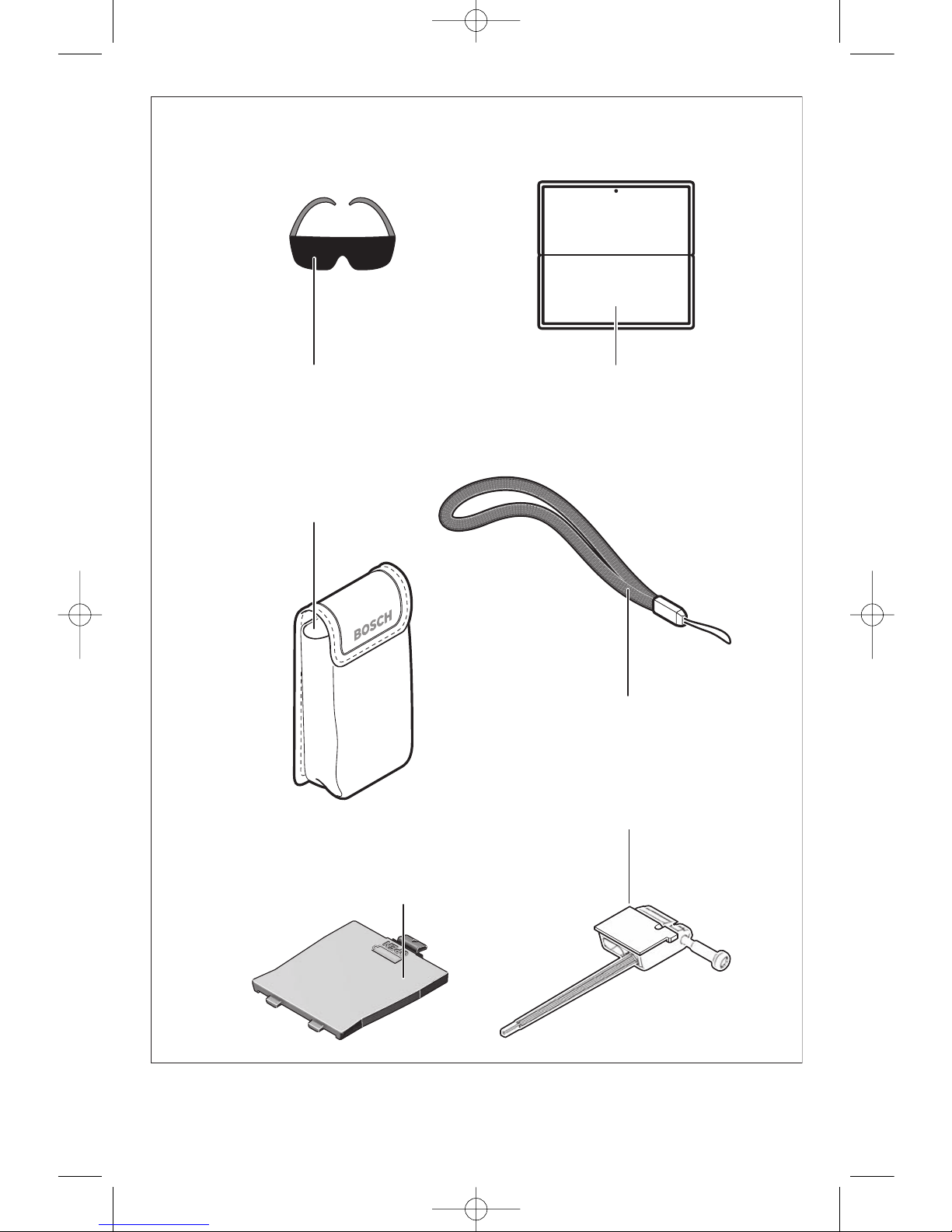
BM 2609140573 04-08 4/15/08 3:11 PM Page 1
-
2-
2.4
ft
0.8 ft
1
.
6
f
t
1
.6
ft
1
.
6
f
t
1
.6
ft
1
.
6
f
t
1
.6
ft
1
.
6
f
t
1
.6
ft
FE
DC
BA
BM 2609140573 04-08 4/15/08 3:11 PM Page 2
-3-
H
G
16
17
18
21
20
19
26
BM 2609140573 04-08 4/15/08 3:11 PM Page 3
-4-
13
12
11
10
9
8
6
7
2
1
3
4
5
14
7
15
a
b
c
d
e
g
h
c
f
BM 2609140573 04-08 4/15/08 3:11 PM Page 4
-5-
24
(1609203U10)
25
(1609203R97)
17
(1609203R93)
14
(1609203R92)
22
(DLA001)
23
(DLA002)
BM 2609140573 04-08 4/15/08 3:11 PM Page 5
-6-
Working safely with the rangefinder is
possible only when the operating and
safety information are read completely
and the instructions contained therein are
strictly followed. Never make warning
labels on the rangefinder unrecognizable.
Never aim the beam at a workpiece with a
reflective surface.
Bright shiny reflective
sheet steel or similar reflective surfaces are
not recommended for laser use. Reflective
surfaces could direct the beam back toward
the operator.
Take care to recognize the accuracy and
range of the device.
Measurement may not
be accurate if used beyond the rated range of
the device.
Use of controls or adjustments or
performance of procedures other than
those specified herein may result in
hazardous radiation exposure.
The use of optical instruments with this
product will increase eye hazards.
Have the rangefinder repaired only through
qualified specialists using original spare
parts.
This ensures that the safety of the
rangefinder is maintained.
Do not allow children to use the laser
rangefinder without supervision.
They
could unintentionally blind other persons.
Do not point the laser beam at persons or
animals and do not look into the laser
beam yourself, not even from a large
distance.
Do not use the laser viewing glasses as
safety goggles.
The laser viewing glasses
are used for improved visualization of the
laser beam, but they do not protect against
laser radiation.
Do not use the laser viewing glasses as
sun glasses or in traffic.
The laser viewing
glasses do not afford complete UV protection
and reduce color perception.
Functional Description
INTENDED USE
The rangefinder is intended for measuring
distances, lengths, heights, clearances and for
calculating areas and volumes. The
rangefinder is suitable for interior and exterior
construction site measuring.
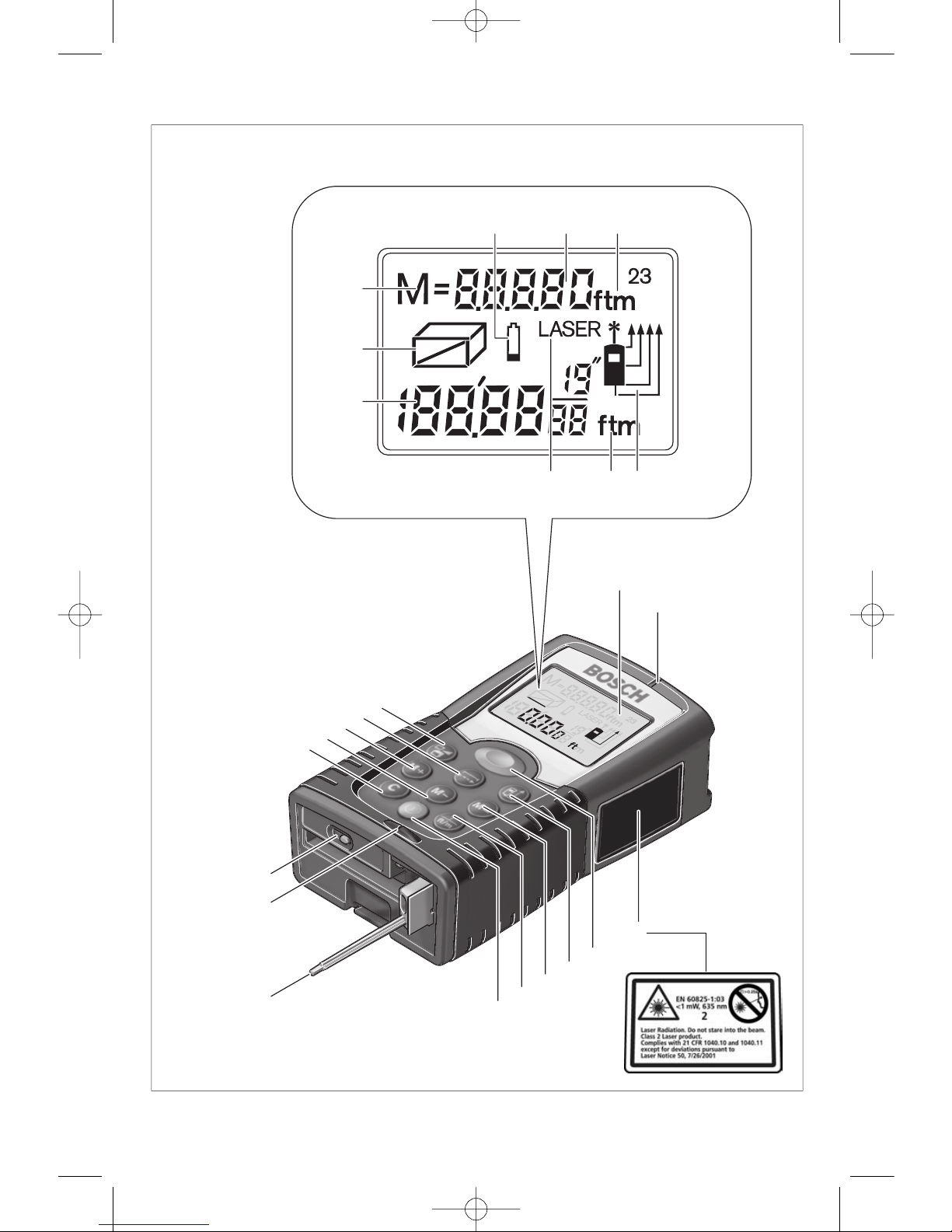
PRODUCT FEATURES
The numbering of the product features shown
refers to the illustration of the digital laser
rangefinder on the graphic pages.
1 Clear button “C”
2 Memory subtraction button “M–”
3
Memory add button “M+”
4
Length and continuous measurement
button
5 Area, volume and indirect length
measurement button
6 Display
7 Alignment aid
8 Laser warning label
9 Measuring button
10 Reference point button
11 Memory retrieve button “M=”
12
Continuous laser beam/change “unit of
measure” button
General Safety Rules
LASER RADIATION. AVOID DIRECT EYE
EXPOSURE. DO NOT stare into the laser light
source. Never aim light at another person or object other
than the workpiece.
Laser light can damage your eyes.
Read all instructions. Failure to follow all
instructions listed below may result in electric
shock, fire and/or serious injury.
DANGER
!
!
WARNING
Safety Rules for Rangefinder
BM 2609140573 04-08 4/15/08 3:11 PM Page 6
-7-
Digital Laser Rangefinder DLR165K
Article number 3 601 K16 014
Dimensions 2 1/4" x 4" x 1 1/4" (58 x 100 x 32 mm)
Measuring range
A)
0.05 ... 50 m
(2 in ... 165 ft)
Distance measuring accuracy
– typical accuracy ±1.5 mm (±1/16 in)
– accuracy range 1.5 mm to 3 mm (±1/16 in to 1/8 in)
B
Measuring duration
– typical
<0.5 s
– maximum 4 s
Lowest indication unit 1/16 in; 0.005 ft; 1 mm
Operating temperature (+14° F … + 122° F)*
– 10 °C ... +50 °C*
*Continuous measurement mode, max. +40 °C (104 °F)
Storage temperature (– 4 °F ... –158 °F)
–20 °C ... +70 °C
Relative air humidity, max. 90 %
Laser class 2
Laser type 635 nm, <1 mW
Laser beam diameter (at 25 °C/77
°F), approx.
– at 10 m (33 ft) distance 6 mm (1/4 in)
– at 50 m (165 ft) distance 30 mm (1 3/16 in)
Batteries 4 x 1.5 V LR03 (AAA)
Rechargeable battery 4 x 1.2 V KR03 (AAA)
Battery service life, approx.
–
Individual measurements, approx.
30000
– Continuous measurement mode, approx. 5 Hours
Automatic switch-off after approx.
– Laser 20 s
– rangefinder (without measurement) 5 min
Weight according to EPTA-Procedure 01/2003
0.18 kg (6.35 oz)
Protection class (excluding battery compartment) IP 54 (dust and splashwater protected)
Technical Data
13 On/Off button
14 Extension pin
15 Latch of the extension pin
16 Latch of battery lid
17 Battery lid
18 Serial number
19 Laser beam outlet
20 Reception lens
21 1/4" threaded hole for mounting optional
tripod
*
22
Laser viewing glasses *
23
Laser target plate*
24
Protective case
25 Hand strap
26 Hand strap mounting post
DISPLAY ELEMENTS
a
Battery indication
b Measured value/result
c Unit of measure
d Measurement reference point
e Laser switched on
f Individual measured value (for length
measurement: result)
g Variable measuring modes
Length measurement
Area measurement
Volume measurement
Indirect length measurement
h Measured value stored
* Optional Accessories
A) The working range increases depending on
how well the laser light is reflected from the
surface of the target (scattered, not reflective)
and with increased brightness of the laser
point to the ambient light intensity (interior
spaces, twilight). In unfavorable conditions
BM 2609140573 04-08 4/15/08 3:11 PM Page 7
-8-
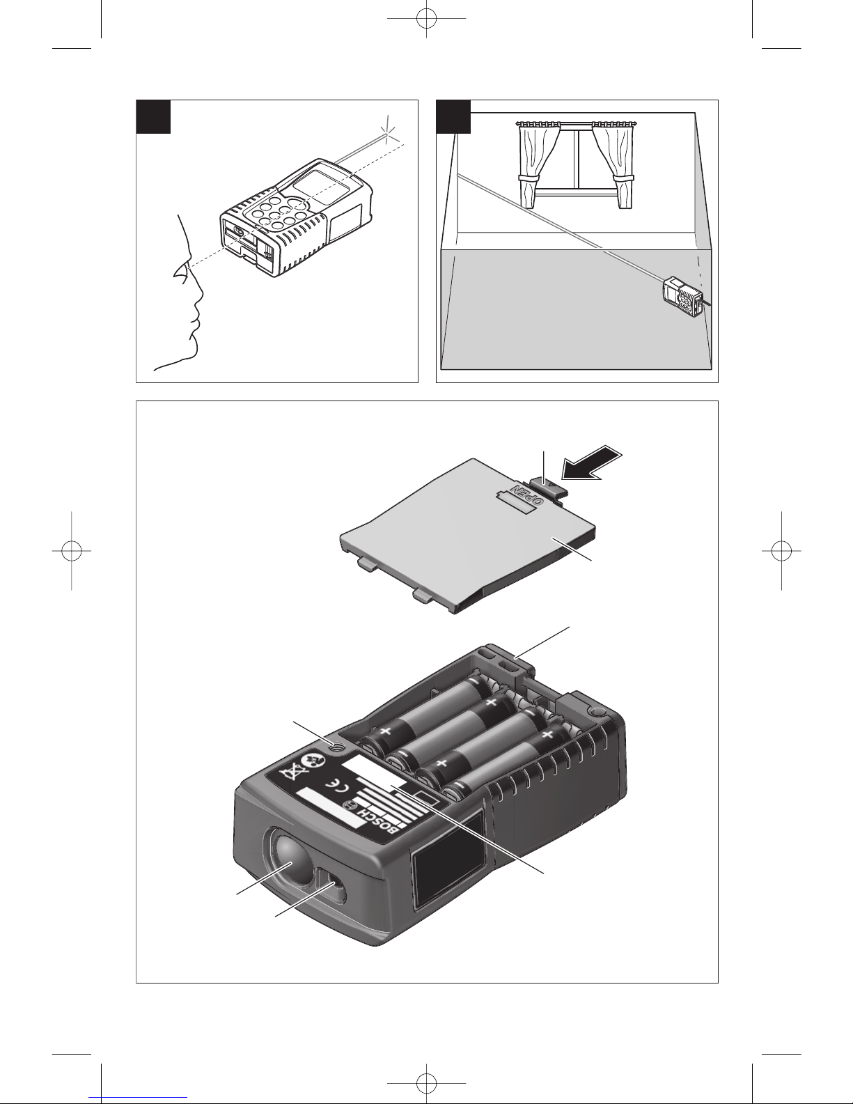
INSERTING/REPLACING THE BATTERY
Use only alkali-manganese or rechargeable
batteries.
Fewer measurements are possible when using
1.2 V rechargeable batteries as compared with
1.5 V batteries.
To open the battery lid
17, press the latch of
the battery lid
16 in the direction of the arrow
and remove the battery lid. Insert the supplied
batteries. When inserting, pay attention to the
correct polarity according to the representation
on the inside of the battery compartment.
When the battery symbol appears in the
display for the first time, then at least 100
measurements are still possible. The batteries
must be replaced when the battery symbol
flashes; taking measurements is no longer
possible.
Always replace all batteries at the same time.
Only use batteries from one brand and with the
identical capacity.
• Remove the batteries from the rangefinder
when not using it for extended periods.
When storing for extended periods, the
batteries can corrode and discharge
themselves.
INSTALLING HAND STRAP
Feed string loop on end of hand strap 25
under hand strap mounting post 26 and pull
out on other side. Feed hand strap
25 through
string loop end and pull tight.
Preparation
(e.g. when measuring outdoors at intense
sunlight), it may be necessary to use the target
plate.
B) +0.1 mm/m (+1/32 in per 26 ft) in case of
unfavorable conditions, e.g. intense sun
irradiation.
Please observe the article number on the type
plate of your rangefinder. The trade names of
the individual rangefinders may vary.
The rangefinder can be clearly identified with
the serial number
18 on the type plate.
Operation
INITIAL OPERATION
• Protect the rangefinder against moisture and
direct sun irradiation.
• Do not expose the rangefinder to extreme
temperatures or variations in temperature.
Switching On and Off
To switch on the rangefinder, either press the
On/Off button
13 or the measuring button 9.
When switching on the rangefinder, the laser
beam is not switched on yet.
To switch off the rangefinder, press the
On/Off button
13.
To save the batteries, the rangefinder switches
off automatically after approx. 5 minutes when
no measurement is carried out.
When a measured value has been stored, it is
retained in automatic switch-off mode. When
switching on the rangefinder again,
“M” is
indicated in the display.
Measuring Procedure
The rangefinder offers a variety of different
measuring modes that can be selected by
pushing the corresponding mode button (see
“Measuring Mode”). After switching on, the
rangefinder is in the “length measurement
mode”.
Also, it is possible to select any of the four
different reference points for the measurement
by pushing the reference point button
10 (see
“Selecting the Reference Point”). After
switching on, the rear edge of the rangefinder
is preset as the reference point.
Upon selection of the measuring mode and the
reference point, all further steps are carried out
by pushing the measuring button 9.
With the reference point selected, place the
rangefinder against the desired measuring line
(e.g. a wall).
Push the measuring button
9 to switch on the
laser beam.
Do not point the laser beam
at persons or animals and
do not look into the laser beam yourself,
not even from a large distance.
!
WARNING
BM 2609140573 04-08 4/15/08 3:11 PM Page 8
Aim the laser beam at the target surface. Push
the measuring button
9 again to initiate the
m
easurement.
In the continuous measurement mode and
continuous laser beam mode, the
measurement already starts upon first
actuation of the measuring button
9.
The measured value appears after 0.5 to 4
seconds. The duration of the measurement
depends on the distance, the light conditions
and the reflection properties of the target
surface. The end of the measurement is
indicated by a signal tone. The laser beam is
switched off automatically upon completion of
the measurement.
When no measurement has taken place
approx. 20 seconds after sighting, the laser
beam is switched off automatically to save the
batteries.
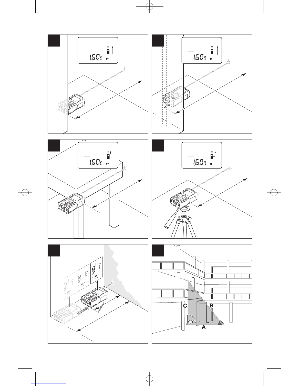
Selecting the Reference Point
(see figures A–D)
For measuring, it is possible to select from four
different reference points:
• The rear edge of the rangefinder (e.g., when
placing the rangefinder flush against a wall),
• The rear edge of the extension pin
14 (e.g.,
for measurements out of corners).
• The front edge of the rangefinder (e.g., as
when measuring from the edge of a table
onward),
• The center of the 1/4” threaded hole
21 (e.g.,
is for measuring with the tripod).
To select the reference point, push button
10
repeatedly until the required reference point is
indicated in the display. Each time after
switching on, the rear edge of the rangefinder
is preset as the reference point.
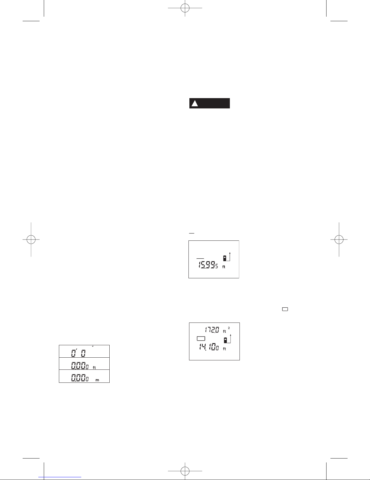
Changing the Unit of Measure
The unit of measure can be changed any time
for display of the measured values, even for
already measured or calculated values.
The three units of
measure shown left are
available for display
of current length
measurements.
Area and volume values
as well as stored measured values can only be
displayed in “ft” or “m”.
To change the unit of measure, push button
12
until a new unit of measure is displayed.
The unit-of-measure setting is retained when
switching the rangefinder on or off.
Continuous Laser Beam
If required, the rangefinder can be set so that
the laser beam stays on in between
measurements. For this, briefly push button
12. The indication “LASER” lights up
continuously in the display.
Do not point the laser beam
at persons or animals and
do not look into the laser beam yourself,
not even from a large distance.
In this setting, the laser beam also remains
switched on between measurements; to take a
measurement, it is only required to push the
measuring button
9 once.
To switch off the continuous laser beam, briefly
push button
12 again or switch the rangefinder
off. When switching on again, the rangefinder
is in normal operation; the laser beam only
appears when pushing the measuring
button
9.
MEASURING MODES
Length Measurement
For length measurements, push button 4
until the indicator for length measurement
appears in the display.
Push the measuring
button 9 once for sighting
and once more to take
the measurement.
The measured value is
indicated at the bottom in
the display.
Area Measurement
For area measurements, push button 5 until
the indicator for area measurement appears
in the display.
Afterwards, measure the
length and the width, one
after another, in the same
manner as a length
measurement. The laser
beam remains switched
on between both measurements.
After taking the second measurement, the
area/surface is automatically calculated and
displayed. The last individual measured value
is indicated at the bottom in the display, while
the final result is shown at the top.
-9-
!
WARNING
BM 2609140573 04-08 4/15/08 3:11 PM Page 9
-10-
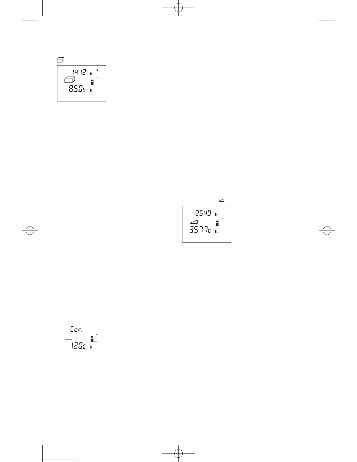
Volume Measurement
For volume measurements, push button 5
until the indicator for volume measurement
appears in the display.
Afterwards, measure the
length, width and the
height, one after another,
in the same manner as
for a length measurement.
The laser beam remains
switched on between all three measurements.
After taking the third measurement, the volume
is automatically calculated and displayed. The
last individual measured value is indicated at
the bottom in the display, while the final result
is shown at the top.
Values exceeding 99990 ft
3
cannot be
displayed; “Err.” is indicated in the display. In
this case, switch the unit of measure to meters
(see “Changing the Unit of Measure”, page 9).
Area or Volume
Rounding of Large Calculations
For values larger than 9999 feet or meters the
rangefinder rounds the calculated value to the
nearest 10 feet or 10 meters. Accuracy in such
situations is always 99.95% or better.
Continuous Measurement (Tracking)
(see figure E)
The continuous measurement mode (tracking)
is used for the transferring of measurements,
e.g., from construction plans. In continuous
measurement mode, the rangefinder can be
moved relative to the target, whereby the
measured value is updated approx. every 0.5
seconds. As an example, the user can move
from a wall to “walk off” the required distance,
while the actual distance can be read
continuously.
For continuous measurement, push button
4
until the indication “Con.” appears in the
display.
Press the measuring
button 9 to initiate the
measuring procedure.
Move the rangefinder until
the required distance
value is indicated at the
bottom of the display.
Pushing the measuring button
9 interrupts the
continuous measurement. The current
measured value is indicated in the display.
Repeated pushing of the measuring button
9
starts the continuous measuring again.
The continuous measuring automatically
switches off after 5 minutes. The last
measured value remains indicated in the
display. The continuous measuring can also be
ended by pushing button
4 or 5, which
changes the measuring mode.
Indirect Length Measurement (see figure F)
The indirect length measurement is used to
measure distances that cannot be measured
directly because an obstacle would obstruct
the laser beam or no target surface is available
as a reflector. (The DLR165 use pythagorean
theorem, a2+b2=c2 to achieve this). Correct
results are achieved only when the laser beam
and the sought distance form an exact right
(90°) angle.
In the illustrated example, the length
C is to be
determined. For this purpose,
A and B must be
measured.
A and C must form a right angle.
For indirect length measurements, push button
5 until the indicator for indirect length
measurement appears in the display.
Measure the distance
A as for a length
measurement. Pay
attention that the line
segment
A and the
sought distance
C form a
right angle. Afterwards, measure the distance
B. The laser beam remains switched on
between both measurements.
Pay attention that the reference point of the
measurement (e.g., the rear edge of the
rangefinder) is at the exact same location for
both measurements.
After completing the second measurement, the
distance
C is calculated automatically. The last
individual measured value is indicated at the
bottom in the display, while the final result
C is
indicated at the top in decimal feet or meters.
Deleting Measured Values
Pushing the clear button 1 deletes the last
individual measuring value determined in all
measuring modes. Pushing the button
repeatedly deletes the individual measured
values in reverse order.
MEMORY MODES
When switching off the rangefinder, the value
in the memory is retained.
BM 2609140573 04-08 4/15/08 3:11 PM Page 10
 Loading...