


 Loading...
DSA E-Series (E2700)
DSA-N2E7X2-08AT | DSA-N2E7Xx-12AT | DSA-N2C7Xx-12AT |
DSX-N1D6Xx-12AT | DSX-N6D6Xx-60AT | DSX-NRCK40-INT
en Installation manual

DSA E-Series (E2700) |
Table of contents | en |
3 |
|
|
|
Table of contents
1 |
Safety |
5 |
1.1 |
Safety message explanation |
5 |
1.2 |
Safety precautions |
5 |
1.3 |
Important safety instructions |
5 |
1.4 |
Warning Notices |
7 |
1.5 |
Caution Notices |
9 |
1.6 |
Notices |
9 |
2 |
|
|
About this guide |
11 |
|
3 |
Registering for E-Series |
12 |
4 |
Preparing for an E2700 controller-drive tray installation |
13 |
4.1 |
Key terms |
13 |
4.2 |
Gathering items |
13 |
4.2.1 |
Basic hardware |
13 |
4.2.2 |
E2700 configuration cables and connectors |
14 |
4.2.3 |
Tools and other items |
15 |
4.3 |
Things to know – copper cables and sas cables |
15 |
4.4 |
Things to know –taking a quick glance at the hardware in a E2700 controller-drive tray |
16 |
|
configuration |
|
5 |
Ethernet network interface cards for the E2700 controller-drive tray |
21 |
6 |
Installing the E2700 controller-drive tray |
22 |
6.1 |
Things to know – general installation |
22 |
6.2 |
Procedure – installing the E2712 controller-drive tray |
22 |
6.3 |
Procedure – installing drives in the E2712 controller-drive |
26 |
7 |
|
|
Connecting the E2700 controller-drive tray to the hosts |
27 |
|
7.1 |
Key terms |
27 |
7.2 |
Things to know – storage array configuration specifications for the E2700 controller- |
27 |
|
drive tray |
|
7.3 |
Things to know – host channels |
27 |
7.4 |
Procedure – connecting the controller-drive tray to the expansion drive trays |
29 |
7.5 |
Connecting to the network |
31 |
7.6 |
Connecting to the management hosts |
31 |
8 |
Installing the drive trays for the E2700 controller-drive tray configurations |
33 |
8.1 |
Things to know – general installation of drive trays with the E2700 controller-drive tray |
33 |
8.2 |
Procedure – installing the DE1600 drive trays |
33 |
8.3 |
Procedure – installing drives in the DE1600 drive trays |
37 |
8.4 |
Procedure – installing the DE6600 drive tray |
38 |
8.5 |
Procedure – installing drives on the de6600 drive tray |
45 |
8.6 |
Things to know – connecting the power cords |
47 |
8.7 |
Procedure – connecting the power cords |
48 |
9 |
|
|
Connecting the E2700 controller-drive tray to the drive trays |
49 |
|
9.1 |
Key terms |
49 |
9.2 |
Things to know – E2700 controller-drive tray |
49 |
9.3 |
Things to know – drive trays |
50 |
9.4 |
Things to know – drive tray cabling configurations for the E2712 controller-drive tray |
50 |
10 |
|
|
Connecting the ethernet cables |
53 |
|
10.1 |
Key terms |
53 |
10.2 |
Things to know – connecting Ethernet cables |
53 |
10.3 |
Procedure – connecting Ethernet cables |
53 |
Bosch Sicherheitssysteme GmbH |
Installation manual |
2016.12 | V2.1 | DOC |

4 en | Table of contents DSA E-Series (E2700)
11 |
Connecting the power cords |
54 |
11.1 |
Things to know – AC power cords |
54 |
11.2 |
Procedure – connecting AC power cords |
54 |
12 |
|
|
Turning on the power and checking for problems in an E2700 controller-drive tray |
55 |
|
|
configuration |
|
12.1 |
Procedure –turning on the power to the storage array and checking for problems in a |
55 |
|
E2700 controller-drive tray configuration |
|
12.2 |
Things to know –LEDs on the E2712 controller-drive tray |
56 |
12.3 |
Things to know – general behavior of the LEDs on the controller-drive tray |
60 |
12.4 |
Things to know – service action allowed LEDs |
62 |
12.5 |
Things to know –LEDs on the DE6600 drive tray |
63 |
12.6 |
LEDs on the DE6600 drive drawers |
66 |
12.7 |
LEDs on the DE6600 drives |
67 |
12.8 |
General behavior of the LEDs on the drive trays |
67 |
12.9 |
Things to know –seven segment display sequence code definitions on the E2700 |
69 |
|
controller-drive tray |
|
12.10 |
Things to know –seven segment component failure identifications for the E2700 |
69 |
|
controller-drive tray |
|
12.11 |
Things to Know – Lock-Down Codes for the Controller-Drive Tray |
70 |
12.12 |
Things to know – seven-segment display use cases |
72 |
12.13 |
Things to know – seven-segment display for the ESMs on the drive trays |
74 |
13 |
|
|
Regulatory compliance statements |
75 |
|
14 |
Trademark information |
76 |
15 |
Additional documentation |
77 |
2016.12 | V2.1 | DOC |
Installation manual |
Bosch Sicherheitssysteme GmbH |
DSA E-Series (E2700) |
Safety | en 5 |
|
|
1 Safety
1.1Safety message explanation
Warning!
!Indicates a hazardous situation which, if not avoided, could result in death or serious injury.
Caution!
!Indicates a hazardous situation which, if not avoided, could result in minor or moderate injury.
Notice!
Indicates a situation which, if not avoided, could result in damage to the equipment or environment, or data loss.
1.2Safety precautions
Caution!
!Installation should only be performed by qualified service personnel in accordance with applicable local codes.
Caution!
|
! |
The Low Voltage power supply unit must comply with EN/UL 60950. The power supply must |
|
be a SELV-LPS unit or a SELV - Class 2 unit (Safety Extra Low Voltage - Limited Power |
|
|
|
|
|
|
Source). |
|
|
|
1.3 |
|
Important safety instructions |
Read, follow, and retain for future reference all of the following safety instructions. Follow all warnings before operating the device.
–Clean only with a dry cloth. Do not use liquid cleaners or aerosol cleaners.
–Do not install device near any heat sources such as radiators, heaters, stoves, or other equipment (including amplifiers) that produce heat.
–Never spill liquid of any kind on the device.
–Take precautions to protect the device from power and lightning surges.
–Unless qualified, do not attempt to service a damaged device yourself. Refer all servicing to qualified service personnel.
–Install in accordance with the manufacturer's instructions in accordance with applicable local codes.
–Use only attachments/accessories specified by the manufacturer.
–Protect all connection cables from possible damage, particularly at connection points.
–Do not defeat the safety purpose of a polarized or ground type plug.
–Permanently connected devices must have an external, readily operable mains plug or all pole mains switch in accordance with installation rules.
–Pluggable devices must have an easily accessible socket-outlet installed near the equipment.
–Unplug the unit from the outlet before cleaning. Follow any instructions provided with the unit.
Bosch Sicherheitssysteme GmbH |
Installation manual |
2016.12 | V2.1 | DOC |

6 en | Safety |
DSA E-Series (E2700) |
|
|
–Any openings in the unit enclosure are provided for ventilation to prevent overheating and ensure reliable operation. Do not block or cover these openings.
–Do not place the unit in an enclosure unless proper ventilation is provided, or the manufacturer's instructions have been adhered to.
–Install the unit only in a dry, weather-protected location.
–Do not use this unit near water, for example near a bathtub, washbowl, sink, laundry basket, in a damp or wet basement, near a swimming pool, in an outdoor installation, or in any area classified as a wet location.
–To reduce the risk of fire or electrical shock, do not expose this unit to rain or moisture.
–Never push objects of any kind into this unit through openings as they may touch dangerous voltage points or short-out parts that could result in a fire or electrical shock.
–Power supply cords should be routed so that they are not likely to be walked on or pinched by items placed upon or against them, playing particular attention to cords and plugs, convenience receptacles, and the point where they exit from the appliance.
–Operate the unit only from the type of power source indicated on the label. Use only the power supply provided or power supply units with UL approval and a power output according to LPS or NEC Class 2.
–Do not open or remove the cover to service this unit yourself. Opening or removing covers may expose you to dangerous voltage or other hazards. Refer all servicing to qualified service personnel.
–Be sure the service technician uses replacement parts specified by the manufacturer. Unauthorized substitutions could void the warranty and cause fire, electrical shock, or other hazards.
–Safety checks should be performed upon completion of service or repairs to the unit to ensure proper operating condition.
–Observe the relevant electrical engineering regulations.
–When installing in a switch cabinet, ensure that the unit and the power supply units have sufficient grounding.
–Connect the unit to an earthed mains socket.
–Use proper CMOS/MOS-FET handling precautions to avoid electrostatic discharge (ESD).
–For protection of the device, the branch circuit protection must be secured with a maximum fuse rating of 16 A. This must be in accordance with NEC800 (CEC Section 60).
–Disconnect the power before moving the unit. Move the unit with care. Excessive force or shock may damage the unit and the hard disk drives.
–All the input/output ports are Safety Extra Low Voltage (SELV) circuits. SELV circuits should only be connected to other SELV circuits.
–If safe operation of the unit cannot be ensured, remove it from service and secure it to prevent unauthorized operation. In such cases, have the unit checked by Bosch Security Systems.
–Disconnect power supply and arrange for the device to be serviced by qualified personnel in the following cases, because safe operation is no longer possible:
–The power cable/plug is damaged.
–Liquids or foreign bodies have entered the device.
–The device has been exposed to water or extreme environmental conditions.
–The device is faulty despite correct installation/operation.
–The device has fallen from a height, or the housing has been damaged.
–The device was stored over a long period under adverse conditions.
–The device performance is noticeably changed.
2016.12 | V2.1 | DOC |
Installation manual |
Bosch Sicherheitssysteme GmbH |
DSA E-Series (E2700) |
Safety | en 7 |
|
|
1.4Warning Notices
Warning!
!If there is evidence of fire, water, or structural damage, never turn on the power to the equipment.Risk of electrical shock
Warning!
!Before removing or installing a power supply, turn off the power switch, and unplug the power cord.Risk of electrical shock
Warning!
!Do not disassemble or remove any part of a Small Form-factor Pluggable (SFP) transceiver because you might be exposed to laser radiation.Risk of exposure to laser radiation
Warning!
Risk of bodily injury
!The battery can weigh up to 10.9 kg (24 lb). When you remove the battery, be prepared to support its weight. If the battery is dropped, the impact might cause bodily injury, including
deep puncture wounds caused by the battery pins.
Warning!
Risk of bodily injury
!cabinet. If the top half of the cabinet is too heavy for the bottom half, the cabinet might fall and cause bodily injury. Always install a component in the lowest available position in the
cabinet.
Warning!If the bottom half of the cabinet is empty, do not install components in the top half of the
Risk of bodily injury
!Attach the stability foot before moving the cabinet. If you do not attach the stability foot, the cabinet might become unstable, or it might fall. This problem is most likely to occur when the
cabinet is moved along inclined surfaces or over uneven surfaces.
Warning!
Risk of bodily injury
Only move a populated cabinet with a forklift or adequate help from other persons. Always
!push the cabinet from the front to prevent it from falling over.
A fully populated cabinet can weigh more than 909 kg (2000 lb). The cabinet is difficult to move, even on a flat surface. If you must move the cabinet along an inclined surface, remove the components from the top half of the cabinet, and make sure that you have adequate help.
Warning!
Risk of fire or chemical burn
!battery used in this device may present a risk of fire or chemical burn if mistreated. DO NOT
disassemble, heat above 60ºC (140ºF), crush or puncture, short circuit external contacts, or dispose of in fire or water. Use appropriate charger only. Replace only with original batteries.Before disposing of a used battery, review the battery warning label. The label reads: The
Bosch Sicherheitssysteme GmbH |
Installation manual |
2016.12 | V2.1 | DOC |

8 en | Safety |
DSA E-Series (E2700) |
|
|
|
|
Warning!
Risk of bodily injury
Only move a populated cabinet with a forklift or adequate help from other persons. Attach the stability foot before moving the cabinet. If you do not attach the stability foot, the cabinet
!might become unstable, or it might fall. Always push the cabinet from the front to prevent it from falling over.
A fully populated cabinet can weigh more than 636 kg (1420 lb). The cabinet is difficult to move, even on a flat surface. If you must move the cabinet along an inclined surface, remove the components from the top half of the cabinet, and make sure that you have adequate help.
Warning!
!A qualified service person is required to make the DC power connection according to NEC and CEC guidelines.Risk of bodily injury
Warning!
Risk of bodily injury
!An empty tray weighs approximately 56.7 kg (125 lb). Three persons are required to safely move an empty tray. If the tray is populated with components, a mechanized lift is required to
safely move the tray.
Warning!
Risk of bodily injury
!Each tray has more than one power cord. To remove all electrical current from the devices, make sure that all of the power cords are disconnected from the power source and that the
two-pole 20-amp circuit breaker for the storage array has been disconnected.
Warning!
!Each tray has more than one power cord. To remove all electrical current from the devices, make sure that all of the power cords are disconnected from the power source.Risk of bodily injury
!
!
!
Warning!
Risk of bodily injury
Do not use equipment in the cabinet as a shelf or work space.
Warning!
Hazardous moving parts
Keep away from moving fan blades.
Warning!
Risk of bodily injury
High leakage current earth connection essential before connecting supply.
2016.12 | V2.1 | DOC |
Installation manual |
Bosch Sicherheitssysteme GmbH |

DSA E-Series (E2700) |
Safety | en 9 |
|
|
1.5Caution Notices
Caution!
Potentially hazardous material
The battery pack contains sealed lead acid batteries that might be considered hazardous material. If you recycle a used battery pack that is not damaged, use the proper facilities. Handle the battery pack according to all applicable regulations.
Caution!
Potentially hazardous material
If the used battery pack is physically damaged or is leaking, DO NOT ship the battery pack to a recycling center. Handling a damaged battery pack exposes you and others to potentially hazardous material. Dispose of the damaged battery pack according to all applicable regulations.
Caution!
Pinching hazard
As you push the canister into the slot, ensure that your fingers are not pinched between the lever and the canister. The lever automatically moves toward the closed position as the canister is pushed into its slot.
Caution!
Potentially hazardous material
The battery pack contains sealed lithium ion batteries that might be considered hazardous material. If the used battery pack is physically damaged and is leaking, DO NOT ship the battery pack to a recycling center. Handling a damaged battery pack exposes you and others to potentially hazardous material. Dispose of the damaged battery pack according to all applicable regulations. If you recycle a used battery pack that is not damaged, use the proper facilities. Handle the battery pack according to all applicable regulations.
Caution!
Electrical grounding hazard
This equipment is designed to permit the connection of the DC supply circuit to the earthing conductor at the equipment.
Caution!
Possible hazard exists
Do not remove more than one canister from the enclosure while power to the enclosure is turned on.
1.6Notices
Notice!
This is a class A product. In a domestic environment this product may cause radio interference, in which case the user may be required to take adequate measures.
Bosch Sicherheitssysteme GmbH |
Installation manual |
2016.12 | V2.1 | DOC |
10 en | Safety |
DSA E-Series (E2700) |
|
|
|
|
Notice!
Video loss is inherent to digital video recording; therefore, Bosch Security Systems cannot be held liable for any damage that results from missing video information.
To minimize the risk of losing information, we recommend multiple, redundant recording systems, and a procedure to back up all analog and digital information.
Disposal
Your Bosch product has been developed and manufactured using highquality materials and components that can be reused.
This symbol means that electronic and electrical devices that have reached the end of their working life must be disposed of separately from household waste.
In the EU, separate collecting systems are already in place for used electrical and electronic products. Please dispose of these devices at your local communal waste collection point or at a recycling center.
Notice!
Do not dispose batteries in household waste. Dispose of batteries only at suitable collection points and, in the case of lithium batteries, mask the poles.
Caution!
Battery replacement - For qualified service personnel only
!the battery as per instructions. Replace only with the same or equivalent type recommended
by the manufacturer. Dispose of the replaced battery in an environmentally friendly way and not with other solid waste. Refer all servicing to qualified service personnel.A lithium battery is located inside the unit enclosure. To avoid danger of explosion, replace
Do not place this unit on an unstable stand, tripod, bracket, or mount. The unit may fall, causing serious injury and/or serious damage to the unit.
Information on sales, delivery, storage, and working life period
No restrictions or conditions apply for the sale or delivery of this product.
If stored under the specified conditions, the storage period is not restricted.
If used for the specified purpose in compliance with the safety instructions and technical specifications, the working life period of the product is in accordance with normal expectations for this type of product.
Information on equipment use
Device is for professional installation only. Operation of the devices is not intended for personal or household use. There are no restrictions to use the device in commercial and industrial areas, except those mentioned in the Safety information.
2016.12 | V2.1 | DOC |
Installation manual |
Bosch Sicherheitssysteme GmbH |
DSA E-Series (E2700) |
About this guide | en 11 |
|
|
2 About this guide
This manual is written for professional system integrators and PC technicians. It provides information for the installation and use of the E2700 controller-drive tray running with SANtricity® Storage Manager software version 11.20, including all attached drive trays. To access the SANtricity® Storage Manager software, go to the online product catalogue.
Installation, configuration and maintenance should be performed by experienced and qualified technicians only.
Conventions in this manual:
For simplicity, the following product names will be used for the following units also described in this manual:
– DE1600 for the DSA E Series 12-bay expansion unit
– DE6600 for the DSA E Series 60-bay expansion unit
See also
–Additional documentation, page 77
Bosch Sicherheitssysteme GmbH |
Installation manual |
2016.12 | V2.1 | DOC |

12 en | Registering for E-Series DSA E-Series (E2700)
3 Registering for E-Series
Before you begin the installation, register your E-Series storage system by using the registration form shipped with the system. The enclosure serial number is located on two places on each enclosure: the large UL label attached to the top of an enclosure, and a silver label attached to the front of the enclosure, either on the bottom lip or the right ear. In both of these places, the enclosure serial number is identified by the text “Serial ” or “S/N ”. Record the serial number of the integrated controller-drive tray for later use. This serial number is required to initiate any support request for your system.
Notice!
The SANtricity® Storage Manager software is also referred to as the storage management software.
2016.12 | V2.1 | DOC |
Installation manual |
Bosch Sicherheitssysteme GmbH |
DSA E-Series (E2700) Preparing for an E2700 controller-drive tray installation | en 13
4 Preparing for an E2700 controller-drive tray installation
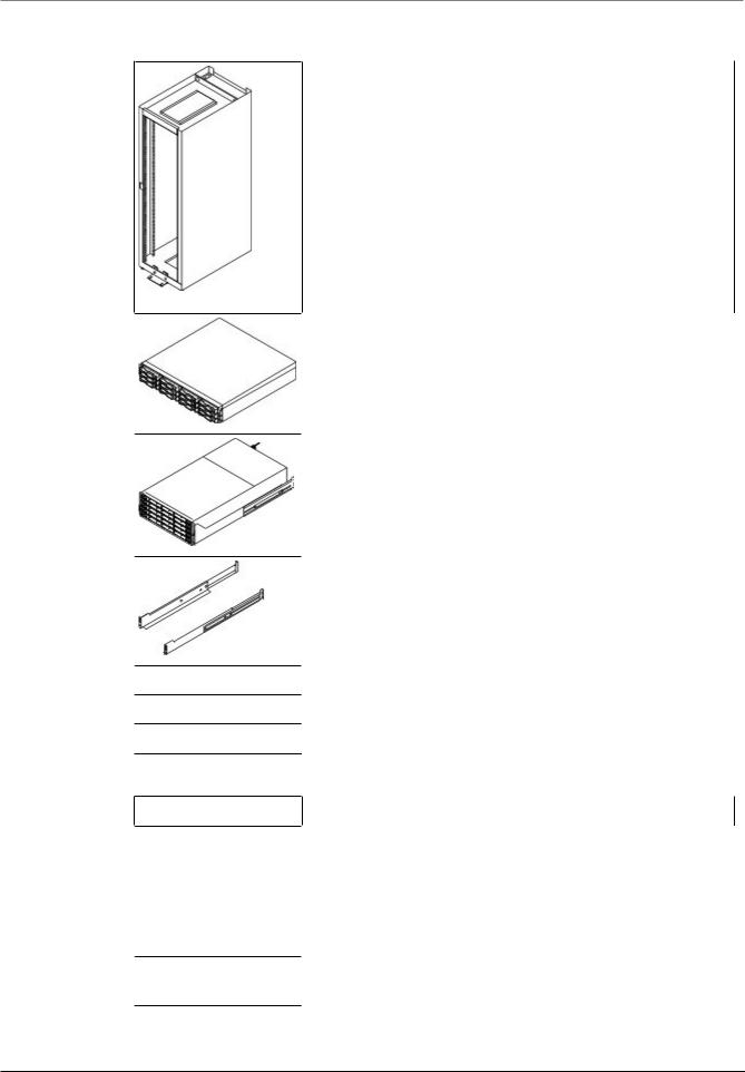
Storage arrays consist of a E2700 controller-drive tray model and can have eight or twelve drive trays in a cabinet:
Use this document to install the E2700 controller-drive tray model and all necessary drive trays for your configuration.
Notice!
Possible hardware damage
To prevent electrostatic discharge damage to the tray, use proper antistatic protection when handling tray components.
4.1Key terms
storage array
A collection of both physical components and logical components for storing data. Physical components include drives, controllers, fans, and power supplies. Logical components include disk pools, volume groups, and volumes. These components are managed by the storage management software.
controller-drive tray
One tray with drives, one or two controllers, fans, and power supplies. The controller-drive tray provides the interface between a host and a storage array.
controller
A circuit board and firmware that is located within a controller tray or a controller-drive tray. A controller manages the input/output (I/O) between the host system and data volumes.
drive tray
One tray with drives, one or two environmental services modules (ESMs), power supplies, and fans. A drive tray does not contain controllers.
environmental services module (ESM)
A canister in the drive tray that monitors the status of the components. An ESM also serves as the connection point to transfer data between the drive tray and the controller.
4.2Gathering items
Before you start installing the controller-drive tray, you must have installed the cabinet in which the controller-drive tray will be mounted.
Use the tables in this section to verify that you have all of the necessary items to install the controller-drive tray.
Notice!
Possible hardware damage
To prevent electrostatic discharge damage to the tray, use proper antistatic protection when handling tray components.
4.2.1Basic hardware
Item
Bosch Sicherheitssysteme GmbH |
Installation manual |
2016.12 | V2.1 | DOC |
14 en | Preparing for an E2700 controller-drive tray installation |
DSA E-Series (E2700) |
|
|
Cabinet
–Make sure that your cabinet meets the installation site specifications of the E2700 storage array components. For more information, refer to the “Storage System Site Preparation Guide”.
–Depending on the power supply limitations of your cabinet, you might need to install more than one cabinet to accommodate the different components of the E2700 storage array.
For instructions on installing the cabinet , refer to the installation guide for your cabinet for instructions on installing the cabinet.
DE1600 drive tray with end caps that are packaged separately. This drive tray can be used with all variations of the E2700 controller-drive tray.
DE6600 drive tray (shown with the separately packaged mounting rails attached). This drive tray can be used with all variations of the E2700 controller-drive tray.
Mounting rails and screws
The mounting rails that are available with the drive tray are designed for an industry-standard cabinet.
iSCSI switch (optional)
Gigabit Ethernet switch for Management (optional)
IP cameras/encoders with iSCSI capabilities
4.2.2E2700 configuration cables and connectors
Item
AC power cords
The controller-drive tray and the drive trays ship with power cords for connecting to an external power source, such as a wall plug. Your cabinet might have special power cords that you use instead of the power cords that ship with the controller-drive tray and the drive trays.
RJ-45 Ethernet cable
This cable is used for 10-Gb/s iSCSI connections.
2016.12 | V2.1 | DOC |
Installation manual |
Bosch Sicherheitssysteme GmbH |
DSA E-Series (E2700) |
Preparing for an E2700 controller-drive tray installation | en 15 |
|
|
Ethernet cable
SAS cables
The HD Mini-SAS (SFF-8644) to Mini-SAS (SFF-8088) SAS cables connect each controller expansion port to the drive tray(s).
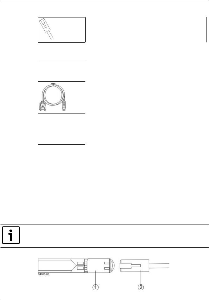
Serial cable
This cable is used for support only. You do not need to connect it during initial installation.
DB9-to-PS2 adapter cable
This cable adapts the DB9 connector on commercially available serial cables to the PS2 connector on the ESM for drive trays in the storage array. This cable is used for support only. You do not need to connect it during installation.
Mini-USB connector
This cable adapts the DB9 connector on commercially available serial cables to the PS2 connector on the controller. This cable is used for support only. You do not need to connect it during installation.
4.2.3Tools and other items
You may need the following equipment:
–Labels: Help you to identify cable connections and lets you more easily trace cables from one tray to another.
–A cart: Holds the tray and components.
–A mechanical lift (optional)
–A Phillips screwdriver
–A flat-blade screwdriver
–An anti-static protection
–A flashlight
4.3Things to know – copper cables and sas cables
The controller-drive tray supports SAS drive connections and SAS, or iSCSI host connections.
Notice!
Your cables might look slightly different from the ones shown. The differences do not affect the performance.
10-Gb/s iSCSI cable connection
Bosch Sicherheitssysteme GmbH |
Installation manual |
2016.12 | V2.1 | DOC |
16 en | Preparing for an E2700 controller-drive tray installation |
DSA E-Series (E2700) |
|
|
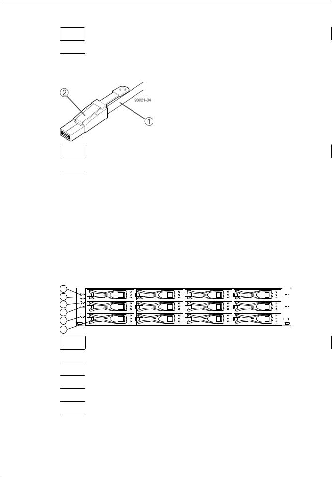
1Active SFP transceiver
2Copper cable with RJ-45 connector
SAS cable connection with SFF-8644 connector
1SAS cable
2SFF-8644 connector
4.4Things to know –taking a quick glance at the hardware in a E2700 controller-drive tray configuration
The E2700 systems always come with eight or twelve hard drives. At least two drives are required for proper operation.
This section provides an overview of hardware described in this document.
Observe the following:
–The top of the controller-drive tray is the side with labels.
–The configuration of the host ports might appear different on your system depending on which host interface card configuration is installed.
E2700 controller-drive tray – front view |
|
1 |
|
2 |
! |
3 |
|
4 |
|
5 |
|
6 |
97001-03 |
1End cap Locate LED
2End cap Service action required LED
3End cap over-temperature LED
4End cap Power LED
5End cap Standby power LED
6Drive canister
2016.12 | V2.1 | DOC |
Installation manual |
Bosch Sicherheitssysteme GmbH |
DSA E-Series (E2700) |
Preparing for an E2700 controller-drive tray installation | en 17 |
|
|
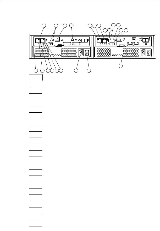
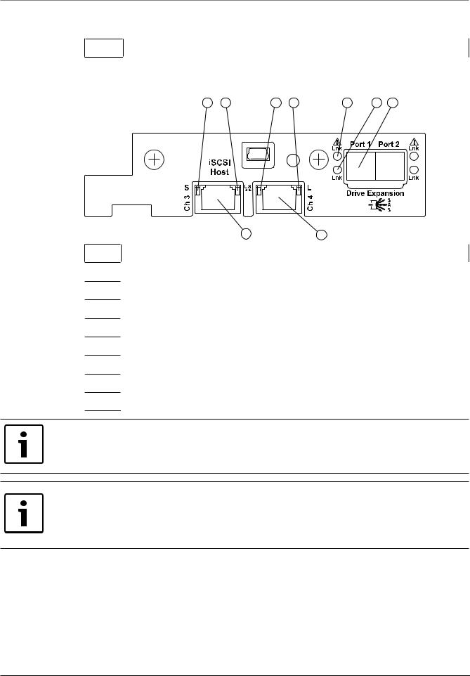
E2700 controller-drive tray – rear view
(right-rear sub plate with a two-port 1-Gb/s or 10-Gb/s iSCSI host interface card)
1 |
2 |
3 |
4 |
5 |
6 |
7 |
8 |
13 |
|
|
|
|
|
|
9 10 |
|
11 12 |
iSCSI Host
S 
 LS
LS  L
L
Ch 3 |
Ch 4 |
25
17 |
18 |
19 20 21 22 |
23 |
24 |
Lnk |
Port 1 Port 2 Lnk |
Lnk |
Lnk |
|
Drive Expansion |
|
S |
|
A |
|
S |
1E2700 controller canister
2Seven-segment display
3USB port
4Serial port
5Ethernet port 1 link rate LED
6Ethernet port 2 link active LED
71 GbE Ethernet management port 2
8SFF-8644 SAS host connector 1
9SAS host 1 link up LED
10SAS host 1 link fault LED
11SAS host 2 link up LED
12SAS host 2 link fault LED
13SFF-8466 SAS host connector 2
14SAS expansion link 1 fault LED
15SAS expansion link 1 up LED
16SFF-8644 SAS connector 1 (expansion)
17Power-fan canister
18Battery service action required LED
19Battery charging LED
20Controller service action allowed LED
21Controller service action required LED
22Cache active LED
23AC power connector
24On/off switch
Bosch Sicherheitssysteme GmbH |
Installation manual |
2016.12 | V2.1 | DOC |
18 en | Preparing for an E2700 controller-drive tray installation |
DSA E-Series (E2700) |
|
|
25 Right rear sub plate (see below)
E2700 right-rear sub plate with a two-port 1-Gb/s or 10-Gb/s iSCSI host interface card
1 |
2 |
4 |
5 |
7 |
8 |
9 |
49006-08
3 |
6 |
1Host interface card channel 3 fault LED
2Host interface card channel 3 link up LED
3iSCSI host interface card channel 3
4iSCSI host interface card channel 4 fault LED
5Host interface card channel 4 link up LED
6iSCSI host interface card channel 4
7SAS expansion port 1 fault LED
8SAS expansion port 1 link up LED
9SFF-8644 SAS port 1 (expansion)
Notice!
Possible equipment damage
You must use the supported drives in the drive tray to ensure proper operation. For information about supported drives, contact a Technical Support Representative.
Notice!
Risk of equipment malfunction
To avoid exceeding the functional and environmental limits, install only drives that have been provided or approved by the original manufacturer. System integrators, resellers, system administrators, or users of the controller-drive tray can install the drives.
2016.12 | V2.1 | DOC |
Installation manual |
Bosch Sicherheitssysteme GmbH |
DSA E-Series (E2700) |
Preparing for an E2700 controller-drive tray installation | en 19 |
|
|
DE1600 drive tray – front view |
|
|
2 |
1 |
3 |
! |
|
|
97001-01 |
1Left end cap (has the drive tray LEDs)
2Drives
3Right end cap
DE1600 drive tray with AC power option - rear view
1 |
2 |
3 |
4 |
5 |
6 |
7 |
11 |
DC |
! |
AC |
|
|
DC |
! |
AC |
|
|
97002-01
8 |
9 |
10 |
1ESM A canister
2Expansion port SFF-8088 connector 1 (IN)
3Expansion port SFF-8088 connector 2 (IN)
4Seven-segment display indicators
5Serial connector
6Ethernet connector
7Expansion port SFF-8088 connector (OUT)
8Power-fan canister
9Power connector
10Power switch
11ESM B canister
Bosch Sicherheitssysteme GmbH |
Installation manual |
2016.12 | V2.1 | DOC |

20 en | Preparing for an E2700 controller-drive tray installation |
DSA E-Series (E2700) |
|
|
DE6600 drive tray – front view with bezel
!
DE6600 drive tray – front view with bezel removed
! |
DE6600 drive tray – rear view
92036-01 |
92034-04 |
1 |
2 |
3 |
4 |
5 |
6 |
1 |
|
|
|
|
|
! |
|
|
|
|
|
|
|
92056-07 |
1 |
Fan canisters |
|
|
|
|
|
2ESM A
3ESM B
4Expansion port SFF-8088 connectors (IN)
5Expansion port SFF-8088 connector (OUT)
6Power canisters
2016.12 | V2.1 | DOC |
Installation manual |
Bosch Sicherheitssysteme GmbH |
DSA E-Series (E2700) Ethernet network interface cards for the E2700 controller-drive tray | en 21
5 Ethernet network interface cards for the E2700 controller-drive tray
The E2700 controller-drive tray supports a two-port 10-Gb/s iSCSI Base-T HIC host interface cards.
Bosch Sicherheitssysteme GmbH |
Installation manual |
2016.12 | V2.1 | DOC |
22 en | Installing the E2700 controller-drive tray DSA E-Series (E2700)
6 Installing the E2700 controller-drive tray
6.1Things to know – general installation
The power supplies meet standard voltage requirements for both domestic and worldwide operation.
Notice!
Make sure that the combined power requirements of your trays do not exceed the power capacity of your cabinet. For power ratings on E2700 controller-drive trays and its related drive trays, refer to the “Storage System Site Preparation Guide”.
6.2Procedure – installing the E2712 controller-drive tray
This procedure describes how to install the mounting rails into an industry standard cabinet. You can install the controller-drive tray into an industry standard cabinet.
Warning!
Risk of bodily injury
!
Two persons are required to safely lift the component.
Warning!
Risk of bodily injury
!cabinet. If the top half of the cabinet is too heavy for the bottom half, the cabinet might fall and cause bodily injury. Always install a component in the lowest available position in the cabinet.
Notice!
Possible hardware damage
To prevent electrostatic discharge damage to the tray, use proper antistatic protection when handling tray components.If the bottom half of the cabinet is empty, do not install components in the top half of the
To install the controller-drive tray:
1.Make sure that the cabinet is in the final location. Make sure that the cabinet installation site meets the clearance requirements.
Note: Fans pull air through the tray from front to back across the drives.
2016.12 | V2.1 | DOC |
Installation manual |
Bosch Sicherheitssysteme GmbH |

DSA E-Series (E2700) |
Installing the E2700 controller-drive tray | en 23 |
|
|
2
78014-02
1 - 76 cm (30 in.) clearance in front of the cabinet
2 - 61 cm (24 in.) clearance behind the cabinet
2.Lower the feet on the cabinet, if required, to keep it from moving.
3.Remove the controller-drive tray and all contents from the shipping carton.
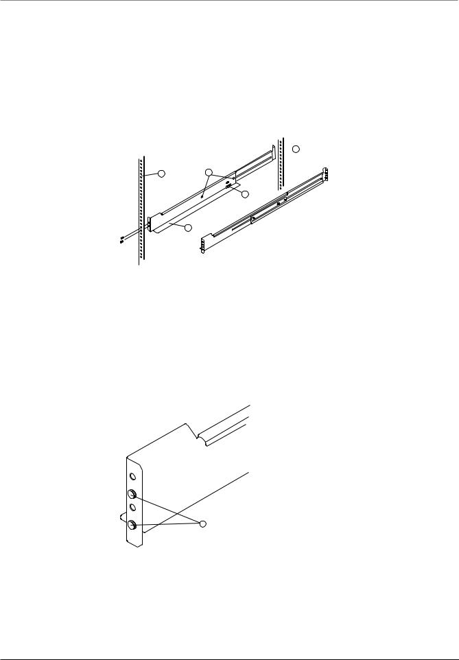
4.Install the mounting rails in the cabinet. For more information, refer to the installation instructions that are included with your mounting rails.
–If you are installing the mounting rails above an existing tray, position the mounting rails directly above the existing tray.
–If you are installing the mounting rails below an existing tray, allow 8.7-cm (3.4-in.) vertical clearance.
2.4
1.
1
3
2
2.
3
1.
4
5
78039-02
1 - Mounting rail
2 - Existing tray
3 - Clearance above and below the existing tray
4 - Screws for securing the mounting rail to the cabinet (front and rear) 5 - Industry standard cabinet
Bosch Sicherheitssysteme GmbH |
Installation manual |
2016.12 | V2.1 | DOC |
24 en | Installing the E2700 controller-drive tray |
DSA E-Series (E2700) |
|
|
Note: Risk of equipment malfunction - To avoid exceeding the functional and environmental limits, install only drives that have been provided or approved by the original manufacturer. Not all controller-drive trays or drive trays are shipped with prepopulated drives. System integrators, resellers, system administrators, or users of the controller-drive tray or drive tray can install the drives.
5.Attach the mounting rails to the cabinet.
–Make sure that the adjustment screws on the mounting rail are loose so that the mounting rail can extend or contract as needed.
 1
1
1 2
4
3
78039-03
1 - Cabinet mounting holes
2 - Adjustment screws for locking the mounting rail length 3 - Mounting rails
4 - Clip for securing the rear of the controller-drive tray
–Place the mounting rail inside the cabinet, and extend the mounting rail until the flanges on the mounting rail touch the inside of the cabinet.
–Make sure that the alignment spacers on the front flange of the mounting rail fit into the mounting holes in the cabinet.
The front flange of each mounting rail has two alignment spacers. The alignment spacers are designed to fit into the mounting holes in the cabinet. The alignment spacers help position and hold the mounting rail.
78039-04
1
1 - Alignment spacers
–Insert one M5 screw through the front of the cabinet and into the top captured nut in the mounting rail. Tighten the screw.
–Insert two M5 screws through the rear of the cabinet and into the captured nuts in the rear flange in the mounting rail. Tighten the screws.
–Tighten the adjustment screws on the mounting rail.
–Repeat the substeps to install the second mounting rail.
2016.12 | V2.1 | DOC |
Installation manual |
Bosch Sicherheitssysteme GmbH |
Loading...