


DNM 60 L
Bedienungsanleitung
Operating instructions
Instructions d’emploi
Instrucciones de servicio
Manual de instruções
Istruzioni d’uso
Gebruiksaanwijzing
Betjeningsvejledning
Bruksanvisning
Brukerveiledningen
Käyttöohje
Οδηγία χειρισµού
Kullanım kılavuzu
取扱説明書
操作指南
DNM 60 L
DNM 120 L
PROFESSIONAL
OBJ_BUCH-17-004.book Page 1 Monday, June 12, 2006 11:10 A
M
2 1 609 929 K06 • 12.6.06
Deutsch. . . . . . . . Seite 7
English. . . . . . . . . Page 16
Français. . . . . . . . Page 25
Español . . . . . . . Página 35
Português . . . . . Página 45
Italiano . . . . . . . . Pagina 54
Nederlands . . . . Pagina 64
Dansk . . . . . . . . . Side 73
Svenska. . . . . . . . Sida 81
Norsk . . . . . . . . . . Side 89
Suomi . . . . . . . . . . Sivu 97
Ελληνικά . . . Σελίδα 105
Türkçe . . . . . . . Sayfa 116
日本語 . . . . . . . . ページ 125
中文 . . . . . . . . . . . . . . 页 134
OBJ_BUCH-17-004.book Page 2 Monday, June 12, 2006 11:10 A
M
1 609 929 K06 • 12.6.06
B
6ab cd e a
7891011
1
5
2
3
4
C
B
A
OBJ_BUCH-17-004.book Page 3 Monday, June 12, 2006 11:10 A
1 609 929 K06 • 12.6.06
∆ > 0,1˚
F
∆ ≤ 0,1˚
∆
10 s
180 ˚
10 s
∆ > 0,1˚
E
∆ ≤ 0,1˚
10 s
∆
180 ˚
10 s
ON
D
OBJ_BUCH-17-004.book Page 4 Monday, June 12, 2006 11:10 A
1 609 929 K06 • 12.6.06
Calibrate
10 s
180 ˚
Calibrate
10 s
180 ˚
Calibrate
10 s
180 ˚
Calibrate
10 s
ON
E
OBJ_BUCH-17-004.book Page 5 Monday, June 12, 2006 11:10 A
M
1 609 929 K06 • 12.6.06
Calibrate
10 s
180 ˚
Calibrate
10 s
180 ˚
Calibrate
10 s
180 ˚
Calibrate
10 s
ON
F
OBJ_BUCH-17-004.book Page 6 Monday, June 12, 2006 11:10 A
M

Deutsch | 71 609 929 K06 • 12.6.06
Funktionsbeschreibung
Optimales Arbeiten
mit dem Messwerkzeug ist nur möglich,
wenn Sie die Bedienungsanleitung und
die Arbeitshinweise
vollständig lesen und die darin
enthaltenen Anweisungen strikt
befolgen. BEWAHREN SIE DIESE
ANWEISUNGEN GUT AUF.
Bitte klappen Sie die Ausklappseite mit
der Darstellung des Messwerkzeugs
auf, und lassen Sie diese Seite aufgeklappt, während Sie die Bedienungsanleitung lesen.
Bestimmungsgemäßer
Gebrauch
Das Messwerkzeug ist bestimmt zum
schnellen und präzisen Messen von
Neigungen und Winkeln.
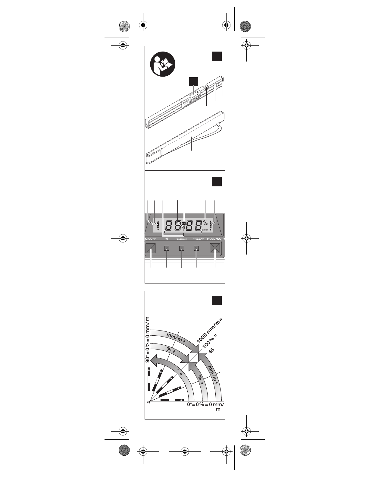
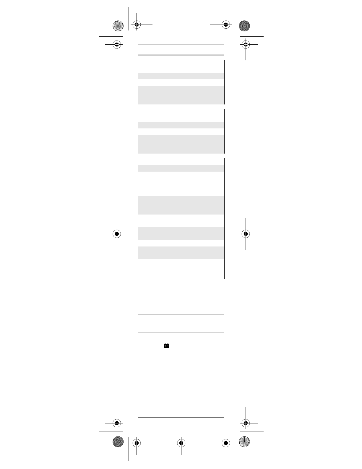
Abgebildete Komponenten
Die Nummerierung der abgebildeten
Komponenten bezieht sich auf die Darstellung des Messwerkzeugs auf der
Grafikseite.
1 Batteriefachdeckel
2 Libelle für waagerechtes Aus-
richten
3 Libelle für senkrechtes Ausrichten
4 Verschlusskappe
5 Schutztasche
6 Display
7 Ein-Aus-Taste „ON/OFF“
8 Taste für akustisches Signal
9 Kalibrierungstaste „Calibrate“
10 Taste für Maßeinheitenwechsel
„° % mm/m“
11 Taste „HOLD/COPY“
Anzeigenelemente
a Ausrichthilfen
b Messwert
c Akustisches Signal
d Batterie-Anzeige
e Maßeinheiten: °; %; mm/m
OBJ_BUCH-17-004.book Page 7 Monday, June 12, 2006 11:10 A
M

8 | Deutsch 1 609 929 K06 • 12.6.06
Technische Daten
Montage
Batterien einsetzen/
wechseln
Verwenden Sie ausschließlich AlkaliMangan-Batterien.
Erscheint im Display 6 das Symbol ,
muss die Batterie gewechselt werden.
Entnehmen Sie den Batteriefachdeckel
1 mit der Batteriehalterung vorsichtig
aus dem Messwerkzeug. Achten Sie
darauf, dass dabei weder die
Anschlusskabel der Batterie noch der
Batteriefachdeckel beschädigt werden.
Größere Beschädigungen an den Auflageflächen des Batteriefachdeckels 1
können zu Fehlmessungen führen.
Digitaler Neigungsmesser
DNM 60 L
PROFESSIONAL
Sachnummer 3 601 K14 000
Länge 600 mm
Gewicht ent-
sprechend
EPTA-Procedure 01/2003
0,7 kg
Digitaler Neigungsmesser
DNM 120 L
PROFESSIONAL
Sachnummer 3 601 K14 100
Länge 1200 mm
Gewicht ent-
sprechend
EPTA-Procedure 01/2003
1,3 kg
DNM 60 L/DNM 120 L
Messbereich 0–360° (4x 90°)
Messgenauigkeit
–0°/90°
– 1–89°
±0,05°
± 0,2°
Nivelliergenauigkeit der Libelle
±0,057°
(± 1 mm/m)
Betriebstemperatur –5 °C ... +50 °C
Lagertemperatur –20 °C ... + 85 °C
Batterie 1 x 9 V 6LR 61
Betriebsdauer ca. 200 h
Bitte beachten Sie die Sachnummer auf
dem Typenschild Ihres Messwerkzeugs,
die Handelsbezeichnungen einzelner
Messwerkzeuge können variieren.
OBJ_BUCH-17-004.book Page 8 Monday, June 12, 2006 11:10 A
M
Deutsch | 91 609 929 K06 • 12.6.06
Wechseln Sie die Batterie. Setzen Sie
den Batteriefachdeckel mit der Batteriehalterung so in das Messwerkzeug
ein, dass die Anschlusskabel nicht eingeklemmt werden.
f Nehmen Sie die Batterie aus
dem Messwerkzeug, wenn Sie
es längere Zeit nicht benutzen.
Die Batterie kann bei längerer
Lagerung korrodieren oder sich
selbst entladen.
Betrieb
Inbetriebnahme
f Schützen Sie das Messwerk-
zeug vor Nässe und direkter
Sonneneinstrahlung.
f Setzen Sie das Messwerkzeug
keinen extremen Temperaturen
oder Temperaturschwankungen
aus.
Ein-/Ausschalten
Drücken Sie zum Ein- bzw. Ausschalten des Messwerkzeugs die Ein-AusTaste „ON/OFF“ 7.
Nach ca. 6 min ohne Durchführung
einer Messung schaltet sich das Messwerkzeug zur Schonung der Batterie
automatisch ab.
Messgenauigkeit überprüfen
(siehe Bild D)
Überprüfen Sie die Genauigkeit des
Messwerkzeugs vor jedem Arbeitsbeginn, nach starken Temperaturänderungen sowie nach starken Stößen.
Vor dem Messen von Winkeln <45°
sollte die Überprüfung an einer ebenen, etwa waagerechten Fläche erfolgen, vor dem Messen von Winkeln
>45° an einer ebenen, etwa senkrechten Fläche.
Schalten Sie das Messwerkzeug ein
und legen Sie es auf die waagerechte
bzw. senkrechte Fläche.
Wählen Sie die Maßeinheit „°“ (siehe
„Maßeinheit wechseln“).
Warten Sie 10 s und notieren Sie dann
den Messwert.
OBJ_BUCH-17-004.book Page 9 Monday, June 12, 2006 11:10 A
M

10 | Deutsch 1 609 929 K06 • 12.6.06
Drehen Sie das Messwerkzeug (wie im
Bild D dargestellt) um 180° um die
senkrechte Achse. Warten Sie erneut
10 s und notieren Sie den zweiten
Messwert.
f Kalibrieren Sie das Messwerk-
zeug nur, wenn die Differenz ∆
beider Messwerte größer als
0,1° ist.
Kalibrieren Sie das Messwerkzeug in
der Lage (senkrecht bzw. waagerecht),
in der die Differenz der Messwerte festgestellt wurde.
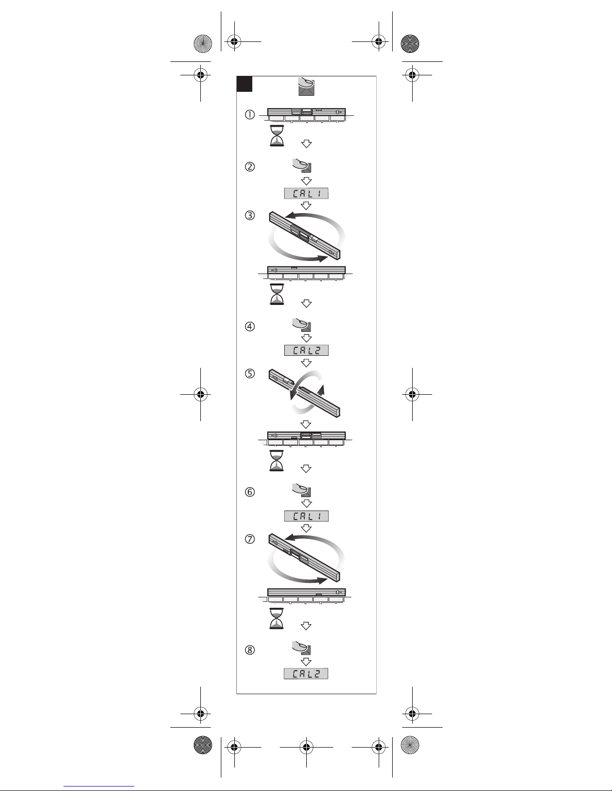
Kalibrieren der waagerechten Auflageflächen (siehe Bild E)
Die Fläche, auf die Sie das Messwerkzeug auflegen, darf nicht mehr als 5°
von der Waagerechten abweichen. Ist
die Abweichung größer, wird die Kalibrierung mit der Anzeige „---“ abgebrochen.
Schalten Sie das Messwerkzeug
ein und legen Sie es so auf die waagerechte Fläche, dass die Libelle 2 nach
oben zeigt und das Display 6 zu Ihnen
gerichtet ist. Warten Sie 10 s.
Drücken Sie dann die Kalibrierungstaste „Calibrate“ 9, bis kurz
„CAL1“ im Display erscheint. Danach
blinkt der Messwert im Display.
Drehen Sie das Messwerkzeug um
180° um die senkrechte Achse, so
dass die Libelle weiterhin nach oben
zeigt, das Display 6 sich jedoch auf der
von Ihnen abgewandten Seite befindet. Warten Sie 10 s.
Drücken Sie dann die Kalibrierungstaste „Calibrate“ 9 erneut. Im
Display wird kurz „CAL2“ angezeigt.
Danach erscheint der Messwert (nicht
mehr blinkend) im Display. Das Messwerkzeug ist nun für diese Auflagefläche neu kalibriert.
Im Anschluss daran müssen Sie
das Messwerkzeug für die gegenüberliegende Auflagefläche kalibrieren.
Dazu drehen Sie das Messwerkzeug
so um die horizontale Achse, dass die
Libelle 2 nach unten und das Display 6
zu Ihnen zeigt. Legen Sie das Messwerkzeug auf die waagerechte Fläche.
Warten Sie 10 s.
Drücken Sie dann die Kalibrierungstaste „Calibrate“ 9, bis kurz
„CAL1“ im Display erscheint. Danach
blinkt der Messwert im Display.
OBJ_BUCH-17-004.book Page 10 Monday, June 12, 2006 11:10 A
M
Deutsch | 111 609 929 K06 • 12.6.06
Drehen Sie das Messwerkzeug um
180° um die senkrechte Achse, so
dass die Libelle weiterhin nach unten
zeigt, das Display 6 sich jedoch auf der
von Ihnen abgewandten Seite befindet. Warten Sie 10 s.
Drücken Sie dann die Kalibrierungstaste „Calibrate“ 9 erneut. Im
Display wird kurz „CAL2“ angezeigt.
Danach erscheint der Messwert (nicht
mehr blinkend) im Display. Das Messwerkzeug ist nun für beide waagerechten Auflageflächen neu kalibriert.
Hinweis: Wird das Messwerkzeug bei
den Schritten und nicht um die im
Bild dargestellte Achse gedreht, kann
die Kalibrierung nicht abgeschlossen werden („CAL2“ erscheint nicht
im Display).
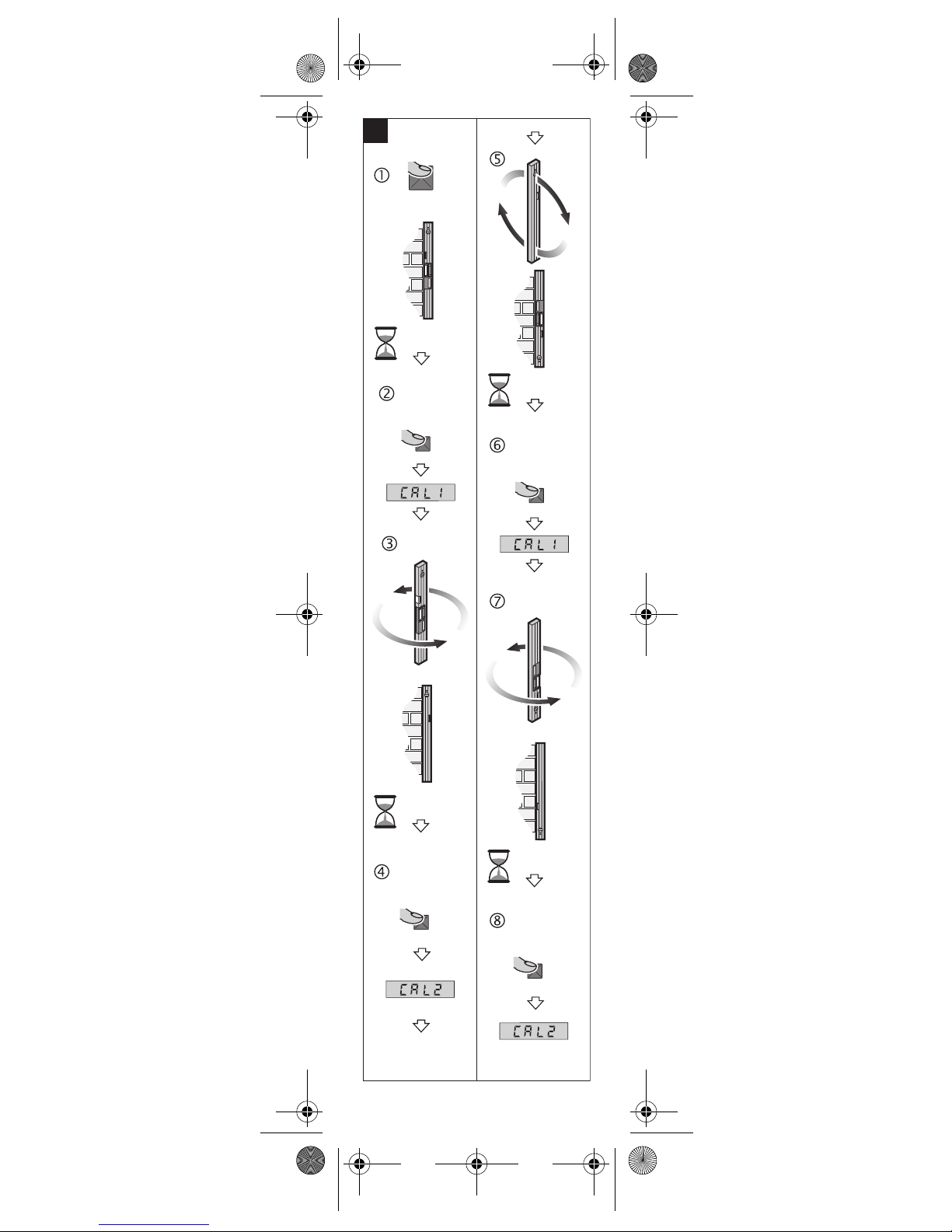
Kalibrieren der senkrechten Auflageflächen (siehe Bild F)
Die Fläche, auf die Sie das Messwerkzeug auflegen, darf nicht mehr als 5°
von der Senkrechten abweichen. Ist
die Abweichung größer, wird die Kalibrierung mit der Anzeige „---“ abgebrochen.
Schalten Sie das Messwerkzeug
ein und legen Sie es so an die senkrechte Fläche, dass die Libelle 3 nach
oben zeigt und das Display 6 zu Ihnen
gerichtet ist. Warten Sie 10 s.
Drücken Sie dann die Kalibrierungstaste „Calibrate“ 9, bis kurz
„CAL1“ im Display erscheint. Danach
blinkt der Messwert im Display.
Drehen Sie das Messwerkzeug um
180° um die senkrechte Achse, so
dass die Libelle weiterhin nach oben
zeigt, das Display 6 sich jedoch auf der
von Ihnen abgewandten Seite befindet. Warten Sie 10 s.
Drücken Sie dann die Kalibrierungstaste „Calibrate“ 9 erneut. Im
Display wird kurz „CAL2“ angezeigt.
Danach erscheint der Messwert (nicht
mehr blinkend) im Display. Das Messwerkzeug ist nun für diese Auflagefläche neu kalibriert.
Im Anschluss daran müssen Sie
das Messwerkzeug für die gegenüberliegende Auflagefläche kalibrieren.
Dazu drehen Sie das Messwerkzeug
so um die horizontale Achse, dass die
Libelle 3 nach unten und das Display 6
zu Ihnen zeigt. Legen Sie das Messwerkzeug an die senkrechte Fläche.
Warten Sie 10 s.
OBJ_BUCH-17-004.book Page 11 Monday, June 12, 2006 11:10 A
M
12 | Deutsch 1 609 929 K06 • 12.6.06
Drücken Sie dann die Kalibrierungstaste „Calibrate“ 9, bis kurz
„CAL1“ im Display erscheint. Danach
blinkt der Messwert im Display.
Drehen Sie das Messwerkzeug um
180° um die senkrechte Achse, so
dass die Libelle weiterhin nach unten
zeigt, das Display 6 sich jedoch auf der
von Ihnen abgewandten Seite befindet. Warten Sie 10 s.
Drücken Sie dann die Kalibrierungstaste „Calibrate“ 9 erneut. Im
Display wird kurz „CAL2“ angezeigt.
Danach erscheint der Messwert (nicht
mehr blinkend) im Display. Das Messwerkzeug ist nun für beide senkrechten
Auflageflächen neu kalibriert.
Hinweis: Wird das Messwerkzeug bei
den Schritten und nicht um die im
Bild dargestellte Achse gedreht, kann
die Kalibrierung nicht abgeschlossen werden („CAL2“ erscheint nicht
im Display).
Arbeitshinweise
Hinweis: Halten Sie die Auflageflä-
chen des Messwerkzeugs sauber.
Schützen Sie das Messwerkzeug vor
Stoß und Schlag. Schmutzpartikel
oder Verformungen können zu Fehlmessungen führen.
Der Messwert wird bei jeder Bewegung des Messwerkzeugs aktualisiert.
Warten Sie nach größeren Bewegungen des Messwerkzeugs mit dem
Ablesen des Messwertes, bis dieser
sich nicht mehr verändert.
Maßeinheit wechseln (siehe Bild C)
Sie können jederzeit zwischen den
Maßeinheiten „°“, „%“ und „mm/m“
wechseln. Drücken Sie dazu die Taste
für Maßeinheitenwechsel 10. Der aktuelle Messwert wird automatisch umgerechnet.
Die Einstellung der Maßeinheit bleibt
beim Aus- und Einschalten des Messwerkzeugs erhalten.
Akustisches Signal
Sie können durch Drücken der Taste
8 ein akustisches Signal ein- und
ausschalten. Bei eingeschaltetem Signal erscheint im Display das Symbol c.
Das Signal zeigt die Messwerte 0° und
90° an.
Die Einstellung des akustischen Signals bleibt beim Aus- und Einschalten
des Messwerkzeugs erhalten.
OBJ_BUCH-17-004.book Page 12 Monday, June 12, 2006 11:10 A
M

Deutsch | 131 609 929 K06 • 12.6.06
Ausrichthilfen
Die Ausrichthilfen a im Display zeigen
an, in welche Richtung das Messwerkzeug gedreht werden muss, um die
Waagerechte bzw. die Senkrechte zu
erreichen.
Bei 0,1° bis 44,9° weisen die Pfeile zur
Waagerechten, bei 45,1° bis 89,9° zur
Senkrechten. Bei 0° und 90° erlöschen die Pfeile.
Drehung der Anzeige
Je nach Lage des Messwerkzeugs
werden Messwert und Maßeinheit im
Display um 180° gedreht angezeigt.
Dadurch ist die Anzeige auch bei
Arbeiten über Kopf ablesbar.
Festhalten/Übertragen eines Messwertes
Mit der Taste „HOLD/COPY“ 11 können zwei Funktionen gesteuert werden:
• Festhalten („Hold“) eines Messwertes, auch wenn das Messwerkzeug
nachträglich bewegt wird,
• Übertragen („Copy“) eines Messwertes.
Funktion „Hold“:
• Schalten Sie das akustische Signal
aus (siehe „Akustisches Signal“).
• Drücken Sie die Taste „HOLD/
COPY“ 11. Der aktuelle Messwert
wird im Display festgehalten, die
Maßeinheit e und die Ausrichthilfen
a blinken.
• Drücken Sie die Taste „HOLD/
COPY“ 11 erneut, um eine neue
Messung zu starten.
Funktion „Copy“:
• Schalten Sie das akustische Signal
ein (siehe „Akustisches Signal“).
• Drücken Sie die Taste „HOLD/
COPY“ 11. Der aktuelle Messwert
wird gespeichert. Ein kurzes Signal
ertönt, die Anzeige für Maßeinheit e
und akustisches Signal c blinken.
• Legen Sie das Messwerkzeug am
Zielort an, an den der Messwert
übertragen werden soll. Die Ausrichthilfen a zeigen die Richtung an,
in die das Messwerkzeug bewegt
werden muss, um den zu kopierenden Winkel zu erreichen. Beim
Erreichen des gespeicherten Winkels ertönt ein akustisches Signal,
die Ausrichthilfen a erlöschen.
• Drücken Sie die Taste „HOLD/
COPY“ 11 erneut, um eine neue
Messung zu starten.
OBJ_BUCH-17-004.book Page 13 Monday, June 12, 2006 11:10 A
M
14 | Deutsch 1 609 929 K06 • 12.6.06
Wartung und Service
Wartung und Reinigung
Lagern und transportieren Sie das
Messwerkzeug nur in der mitgelieferten Schutztasche.
Halten Sie das Messwerkzeug stets
sauber, um gut und sicher zu arbeiten.
Tauchen Sie das Messwerkzeug nicht
ins Wasser oder andere Flüssigkeiten.
Wischen Sie Verschmutzungen mit
einem feuchten, weichen Tuch ab. Verwenden Sie keine Reinigungs- oder
Lösemittel.
Sollte das Messwerkzeug trotz sorgfältiger Herstellungs- und Prüfverfahren
einmal ausfallen, ist die Reparatur von
einer autorisierten Kundendienststelle
für Bosch-Elektrowerkzeuge ausführen
zu lassen.
Geben Sie bei allen Rückfragen und
Ersatzteilbestellungen bitte unbedingt
die 10-stellige Sachnummer laut
Typenschild des Messwerkzeugs an.
Senden Sie im Reparaturfall das Messwerkzeug in der Schutztasche 5 ein.
Ersatzteile
Batteriefachdeckel 1 . . 1 609 203 525
Verschlusskappe 4 . . . 1 609 203 S39
Schutztasche 5
• für DNM 60 L . . . .1 609 203 R95
• für DNM 120 L . . . 1 609 203 R96
Service und Kundenberater
Explosionszeichnungen und Informationen zu Ersatzteilen finden Sie unter:
www.bosch-pt.com
www.powertool-portal.de, das
Internetportal für Handwerker und
Heimwerker.
www.ewbc.de, der Informations-Pool
für Handwerk und Ausbildung.
Deutschland
Robert Bosch GmbH
Servicezentrum Elektrowerkzeuge
Zur Luhne 2
37589 Kalefeld
✆ . . . . . . . . . . . . . . 0 18 05/70 74 10
Fax . . . . . . . . . . . . . 0 18 05/70 74 11
OBJ_BUCH-17-004.book Page 14 Monday, June 12, 2006 11:10 A
M
Deutsch | 151 609 929 K06 • 12.6.06
Österreich
ABE Service GmbH
Jochen-Rindt-Straße 1
1232 Wien
✆ Service . . . . . . +43 (0)1/61 03 80
Fax . . . . . . . . . +43 (0)1/61 03 84 91
✆ Kundenberater
. . . . . . . . . . .+43 (0)1/7 97 22 30 66
E-Mail: abe@abe-service.co.at
Schweiz
✆ . . . . . . . . . . . . . . . 0 44/8 47 15 11
Fax . . . . . . . . . . . . . . 0 44/8 47 15 51
Luxemburg
✆ . . . . . . . . . . . . +32 (0)70/22 55 65
Fax . . . . . . . . . . . +32 (0)70/22 55 75
E-Mail:
outillage.gereedschap@be.bosch.com
Entsorgung
Messwerkzeuge, Zubehör und Verpackungen sollen einer umweltgerechten
Wiederverwertung zugeführt werden.
Nur für EU-Länder:
Werfen Sie Messwerkzeuge nicht in den
Hausmüll!
Gemäß der Europäischen Richtlinie 2002/
96/EG über Elektround Elektronik-Altgeräte und ihrer
Umsetzung in nationales Recht müssen nicht mehr gebrauchsfähige Messwerkzeuge getrennt gesammelt und
einer umweltgerechten Wiederverwertung zugeführt werden.
Akkus/Batterien:
Werfen Sie Akkus/Batterien nicht in
den Hausmüll, ins Feuer oder ins Wasser. Akkus/Batterien sollen gesammelt,
recycelt oder auf umweltfreundliche
Weise entsorgt werden.
Nur für EU-Länder:
Gemäß der Richtlinie 91/157/EWG
müssen defekte oder verbrauchte
Akkus/Batterien recycelt werden.
Nicht mehr gebrauchsfähige Akkus/
Batterien können direkt abgegeben
werden bei:
Deutschland
Recyclingzentrum Elektrowerkzeuge
Osteroder Landstraße 3
37589 Kalefeld
Schweiz
Batrec AG
3752 Wimmis BE
Änderungen vorbehalten.
OBJ_BUCH-17-004.book Page 15 Monday, June 12, 2006 11:10 A
M
16 | English 1 609 929 K06 • 12.6.06
Functional
Description
Optimal working with
the measuring tool is
possible only when
the operating instructions and information
are read completely,
and the instructions contained
therein are strictly followed. SAVE
THESE INSTRUCTIONS.
Please unfold the fold-out page with
the representation of the measuring
tool and leave it unfolded while reading
the operating instructions.
Intended Use
The measuring tool is intended for
quick and precise measurement of
inclinations and angles.
Product Features
The numbering of the product features
shown refers to the illustration of the
measuring tool on the graphic page.
1 Battery lid
2 Spirit level for horizontal alignment
3 Spirit level for vertical alignment
4 Closing cap
5 Protective case
6 Display
7 “ON/OFF” button
8 Acoustic signal button
9 “Calibrate” function button
10 “° % mm/m” button for changing
the unit of measure
11 “HOLD/COPY” button
Display Elements
a Alignment aides
b Reading
c Acoustic signal
d Battery indication
e Units of measure: °; %; mm/m
OBJ_BUCH-17-004.book Page 16 Monday, June 12, 2006 11:10 A
M
English | 171 609 929 K06 • 12.6.06
Technical Data
Assembly
Inserting/Replacing
the Battery
Use only alkali-manganese batteries.
When the symbol appears in the
display 6, the battery must be replaced.
Carefully remove the battery lid 1 with
the battery holder out of the measuring
tool. Pay attention that neither the connection cables of the battery nor the
battery lid are damaged. Excessive
damage on the supporting surface of
the battery lid 1 can lead to faulty
measurements.
Digital level DNM 60 L
PROFESSIONAL
Article number 3 601 K14 000
Length 600 mm
Weight accord-
ing to EPTA-Procedure 01/2003
0.7 kg
Digital level DNM 120 L
PROFESSIONAL
Article number 3 601 K14 100
Length 1200 mm
Weight accord-
ing to EPTA-Procedure 01/2003
1.3 kg
DNM 60 L/DNM 120 L
Measuring range 0–360° (4x 90°)
Measuring
accuracy
–0°/90°
– 1–89°
±0.05°
± 0.2°
Levelling
accuracy of the
spirit level
±0.057°
(± 1 mm/m)
Operating
temperature –5 °C ... +50 °C
Storage
temperature
–20 °C ... + 85 °C
Battery 1 x 9 V 6LR 61
Operating life
time, approx.
200 h
Please observe the article number on the
type plate of your measuring tool. The trade
names of the individual measuring tools
may vary.
OBJ_BUCH-17-004.book Page 17 Monday, June 12, 2006 11:10 A
M
18 | English 1 609 929 K06 • 12.6.06
Replace the battery. Place the battery
lid with the battery holder into the
measuring tool in such a manner that
the connection cables are not trapped.
f If the measuring tool is not
used for a long period of time,
the battery must be removed.
The battery can corrode or discharge itself over long periods.
Operation
Initial Operation
f Protect the measuring tool
against moisture and direct sun
irradiation.
f Do not expose the measuring
tool to extreme temperatures
or variations in temperature.
Switching On and Off
Press the “ON/OFF” switch 7 to
switch the measuring tool on or off.
After approx. 6 minutes without performing a measurement, the measuring
tool switches off automatically in order
prolong the service life of the battery.
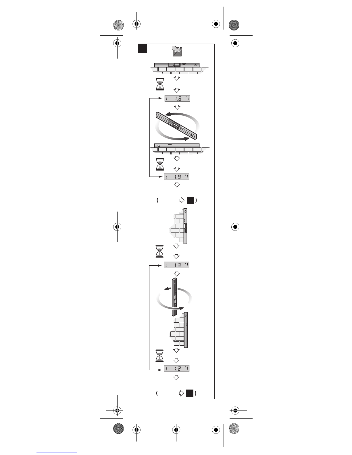
Checking the Measuring Accuracy
(see figure D)
Check the accuracy of the measuring
tool each time before using, after
extreme temperature changes as well
as after heavy jolts or impact.
Before measuring angles <45°, the
accuracy check should take place on a
level and roughly horizontal surface;
before measuring angles >45°, on a
level and roughly vertical surface.
Switch the measuring tool on and
place it on the horizontal or vertical surface.
Select the unit of measure “°” (see
“Changing the Unit of Measure”).
Wait for 10 s and note down the measured value.
OBJ_BUCH-17-004.book Page 18 Monday, June 12, 2006 11:10 A
M

English | 191 609 929 K06 • 12.6.06
Rotate the measuring tool by 180°
around the vertical axis (as shown in
figure D). Wait again for 10 s and note
down the second measured value.
f Calibrate the measuring tool
only when the difference ∆
between both reading values is
greater than 0.1°.
Calibrate the measuring tool in the
position (vertical or horizontal), in
which the difference of the measured
values has been determined.
Calibration for Horizontal
Surfaces (see figure E)
The surface onto which you place the
measuring tool must not deviate from
the horizontal line by more than 5°. If
the deviation is greater, the calibration
process is discontinued with the indication “---” .
Switch the measuring tool on and
place it onto the horizontal surface in
such a manner that the spirit level 2
faces upward and the display 6 faces
you. Wait for 10 s.
Then press the “Calibrate” func-
tion button 9 until “CAL1” is briefly
indicated in the display. Afterwards the
measured value flashes in the display.
Turn the measuring tool by 180°
around the vertical axis so that the
spirit level still faces upward, but the
display 6 faces away from you. Wait for
10 s.
Then press the “Calibrate” func-
tion button 9 again. “CAL2” is briefly
indicated in the display. Afterwards the
measured value appears in the display
(no longer flashing). The measuring
tool is now newly calibrated for this
surface.
Afterwards you must calibrate the
measuring tool for the opposite surface. For this, turn the measuring tool
around its horizontal axis in such a
manner that the spirit level 2 faces
downward and the display 6 faces you.
Place the measuring tool onto the horizontal surface. Wait for 10 s.
Then press the “Calibrate” func-
tion button 9 until “CAL1” is briefly
indicated in the display. Afterwards the
measured value flashes in the display.
OBJ_BUCH-17-004.book Page 19 Monday, June 12, 2006 11:10 A
M

20 | English 1 609 929 K06 • 12.6.06
Turn the measuring tool 180°
around the vertical axis so that the
spirit level still faces downward but the
display 6 is facing away from you. Wait
for 10 s.
Then press the “Calibrate” func-
tion button 9 again. “CAL2” is briefly
indicated in the display. Afterwards the
measured value appears in the display
(no longer flashing). The measuring
tool is now newly calibrated for both
horizontal surfaces.
Note: If the measuring tool is not
turned around the axis shown in the figure in steps and , then the cali-
bration cannot be completed
(“CAL2” is not indicated in the display).
Calibration for Vertical Surfaces
(see figure F)
The surface onto which you place the
measuring tool must not deviate from
the vertical line by more than 5 °. If the
deviation is greater, the calibration
process is discontinued with the indication “---”.
Switch the measuring tool on and
place it against the vertical surface in
such a manner that the spirit level 3
faces upward and the display 6 faces
you. Wait for 10 s.
Then press the “Calibrate” func-
tion button 9 until “CAL1” is briefly
indicated in the display. Afterwards the
measured value flashes in the display.
Turn the measuring tool by 180°
around the vertical axis so that the
spirit level still faces upward, but the
display 6 faces away from you. Wait for
10 s.
Then press the “Calibrate” func-
tion button 9 again. “CAL2” is briefly
indicated in the display. Afterwards the
measured value appears in the display
(no longer flashing). The measuring
tool is now newly calibrated for this
surface.
Afterwards you must calibrate the
measuring tool for the opposite surface. For this, turn the measuring tool
around its horizontal axis in such a
manner that the spirit level 3 faces
downward and the display 6 faces you.
Place the measuring tool against the
vertical surface. Wait for 10 s.
OBJ_BUCH-17-004.book Page 20 Monday, June 12, 2006 11:10 A
M
English | 211 609 929 K06 • 12.6.06
Then press the “Calibrate” func-
tion button 9 until “CAL1” is briefly
indicated in the display. Afterwards the
measured value flashes in the display.
Turn the measuring tool 180°
around the vertical axis so that the
spirit level still faces downward but the
display 6 is facing away from you. Wait
for 10 s.
Then press the “Calibrate” func-
tion button 9 again. “CAL2” is briefly
indicated in the display. Afterwards the
measured value appears in the display
(no longer flashing). The measuring
tool is now newly calibrated for both
vertical surfaces.
Note: If the measuring tool is not
turned around the axis shown in the figure in steps and , then the cali-
bration cannot be completed
(“CAL2” is not indicated in the display).
Operating Instructions
Note: Keep the surfaces of the meas-
uring tool clean. Protect the measuring
tool against shock and impact. Debris
particles or deformations can lead to
faulty measurements.
For each movement of the measuring
tool, the measured value is updated.
After moving the measuring tool to any
extent, wait until the measured value no
longer changes before reading the
value.
Changing the Unit of Measure
(see figure C)
It is possible to change between the
“°”, “%” and “mm/m” units of measure
at any time. For this, press the “° %
mm/m” button 10. The current measured value is converted automatically.
The unit-of-measure setting is retained
when switching the measuring tool on
or off.
Acoustic Signal
An acoustic signal can be switched on
and off by pressing the button 8.
When the signal is switched on, the
c symbol appears in the display. The
signal indicates the measured values
0° and 90°.
The acoustic signal setting is retained
after switching the measuring tool on
and off.
OBJ_BUCH-17-004.book Page 21 Monday, June 12, 2006 11:10 A
M

22 | English 1 609 929 K06 • 12.6.06
Alignment Aids
The alignment aids a on the display
indicate in which direction the measuring tool is to be turned in order to reach
the horizontal or vertical plane.
For 0.1° to 44.9° the arrows point to
the horizontal, for 45.1° to 89.9° to the
vertical plane. For 0° and 90° the
arrows go out.
Rotation of the Reading
Depending on the position of the
measuring tool, the measured value
and the unit of measure are indicated in
the display rotated by 180°. Thus, the
indication can also be read for overhead work.
Holding/Copying a Measured
Value
Two functions can be controlled with
the “HOLD/COPY” 11 button:
• Holding (“Hold”) of a measured
value, even when the measuring
tool is moved afterwards,
• Copying (“Copy”) of a measured
value.
“Hold” function:
• Switch the acoustic signal off (see
“Acoustic Signal”).
• Press the “HOLD/COPY” 11 button. The current measured value on
the display is held, the unit of measure e and the alignment aids a flash.
• Press the “HOLD/COPY” 11 button again to start a new measurement.
“Copy” function:
• Switch the acoustic signal on (see
“Acoustic Signal”).
•Press the “HOLD/COPY” 11 button. The current measured value is
stored. A short signal sounds, the
unit of measure e and acoustic signal c flash.
• Position the measuring tool at the
target location where the measured
value is to be copied. The alignment
aids a indicate the direction in which
the measuring tool has to be moved
in order to reach the angle to be
copied. An acoustic signal sounds
upon reaching the memorised angle
and the alignment aids a go out.
• Press the “HOLD/COPY” 11 button again to start a new measurement.
OBJ_BUCH-17-004.book Page 22 Monday, June 12, 2006 11:10 A
M
English | 231 609 929 K06 • 12.6.06
Maintenance and
Service
Maintenance and Cleaning
Store and transport the measuring tool
only in the supplied protective case.
For safe and proper working, always
keep the measuring tool clean.
Do not immerse the measuring tool into
water or other fluids.
Wipe off debris using a moist and soft
cloth. Do not use any cleaning agents
or solvents.
If the measuring tool should fail despite
the care taken in manufacturing and
testing procedures, repair should be
carried out by an authorized after-sales
service centre for Bosch power tools.
In all correspondence and spare parts
orders, please always include the
10-digit article number given on the
type plate of the measuring tool.
In case of repairs, send in the measuring tool packed in its protective case 5.
Spare Parts
Battery lid 1 . . . . . . . . 1 609 203 525
Closing cap 4 . . . . . .1 609 203 S39
Protective case 5
• for DNM 60 L . . . .1 609 203 R95
• for DNM 120 L . .1 609 203 R96
Service and Customer
Assistance
Exploded views and information on
spare parts can be found under:
www.bosch-pt.com
Great Britain
Robert Bosch Ltd. (B.S.C.)
P.O. Box 98
Broadwater Park
North Orbital Road
Denham-Uxbridge
Middlesex UB 9 5HJ
✆ Service:
. . . . . . . . . . +44 (0) 18 95 / 83 87 82
✆ Advice line:
. . . . . . . . . . +44 (0) 18 95 / 83 87 91
Fax:. . . . . . . +44 (0) 18 95 / 83 87 89
OBJ_BUCH-17-004.book Page 23 Monday, June 12, 2006 11:10 A
M
24 | English 1 609 929 K06 • 12.6.06
Ireland
Beaver Distribution Ltd.
Greenhills Road
Tallaght-Dublin 24
✆ Service: . . .+353 (0)1 / 4 14 94 00
Fax:. . . . . . . . .+353 (0)1 / 4 59 80 30
Australia and New Zealand
Robert Bosch Australia Pty. Ltd.
RBAU/SPT
1555 Centre Road
P.O. Box 66
3168 Clayton/Victoria
✆ . . . . . . . . +61 (0)1 / 3 00 30 70 44
Fax:. . . . . . . +61 (0)1 / 3 00 30 70 45
www.bosch.com.au
Disposal
Measuring tools, accessories and
packaging should be sorted for environmental-friendly recycling.
Only for EC countries:
Do not dispose of
measuring tools into
household waste!
According the European Guideline 2002/
96/EC for Waste Electrical and Electronic Equipment and its
implementation into national right,
measuring tools that are no longer usable must be collected separately and
disposed of in an environmentally correct manner.
Battery packs/batteries:
Do not dispose of battery packs/batteries into household waste, fire or
water. Battery packs/batteries should
be collected, recycled or disposed of
in an environmental-friendly manner.
Only for EC countries:
Defective or dead out battery packs/
batteries must be recycled according
the guideline 91/157/EEC.
Batteries no longer suitable for use can
be directly returned at:
Great Britain
Robert Bosch Ltd. (B.S.C.)
P.O. Box 98
Broadwater Park
North Orbital Road
Denham-Uxbridge
Middlesex UB 9 5HJ
✆ Service:
. . . . . . . . . . +44 (0) 18 95 / 83 87 82
✆ Advice line:
. . . . . . . . . . +44 (0) 18 95 / 83 87 91
Fax:. . . . . . . +44 (0) 18 95 / 83 87 89
Subject to change without notice.
OBJ_BUCH-17-004.book Page 24 Monday, June 12, 2006 11:10 A
M

Français | 251 609 929 K06 • 12.6.06
Description du
fonctionnement
Un travail optimal avec
cet appareil de mesure
n’est possible que si
vous lisez complètement les instructions
d’utilisation et les instructions de travail et que vous
respectiez strictement les indications qui y sont mentionnées.
GARDER PRECIEUSEMENT CES
INSTRUCTIONS DE SECURITE.
Dépliez le volet sur lequel l’appareil de
mesure est représenté de manière graphique. Laissez le volet déplié pendant
la lecture de la présente notice d’utilisation.
Utilisation conforme
L’appareil de mesure est conçu pour le
mesurage rapide et précis d’inclinaisons et d’angles.
Eléments de l’appareil
La numérotation des éléments de
l’appareil se réfère à la représentation
de l’appareil de mesure sur la page
graphique.
1 Couvercle du compartiment à piles
2 Bulle d’air pour orientation
horizontale
3 Bulle d’air pour orientation
verticale
4 Capuchon
5 Etui de protection
6 Afficheur
7 Interrupteur Marche/Arrêt
«ON/OFF»
8 Touche pour signal acoustique
9 Touche d’ajustage « Calibrate »
10 Touche de changement de l’unité
de mesure « ° % mm/m »
11 Touche de « HOLD/COPY »
Eléments d’affichage
a Traits de visée
b Valeur de mesure
c Signal acoustique
d Indicateur de charge de la pile
e Unités de mesure : ° ; % ; mm/m
OBJ_BUCH-17-004.book Page 25 Monday, June 12, 2006 11:10 A
M
26 | Français 1 609 929 K06 • 12.6.06
Caractéristiques
techniques
Montage
Mise en place/changement
des piles
N’utiliser que des piles alcalines au
manganèse.
Si le symbole apparaît sur l’afficheur 6 la pile doit être remplacée.
Indicateur
de pente
numérique
DNM 60 L
PROFESSIONAL
N° d’article 3 601 K14 000
Longueur 600 mm
Poids suivant
EPTA-Procédure
01/2003
0,7 kg
Indicateur
de pente
numérique
DNM 120 L
PROFESSIONAL
N° d’article 3 601 K14 100
Longueur 1200 mm
Poids suivant
EPTA-Procédure
01/2003
1,3 kg
DNM 60 L/DNM 120 L
Plage de mesure 0–360° (4 x 90°)
Précision de
mesure
–0°/90°
– 1–89°
±0,05°
± 0,2°
Précision de
nivellement de la
bulle d’air
±0,057°
(± 1 mm/m)
Température de
service –5 °C ... +50 °C
Température de
stockage
–20 °C ... + 85 °C
Pile 1 x 9 V 6LR 61
Durée de service
env.
200 h
Faire attention au numéro d’article se trouvant sur la plaque signalétique de l’appareil
de mesure. Les désignations commerciales
des différents appareils peuvent varier.
OBJ_BUCH-17-004.book Page 26 Monday, June 12, 2006 11:10 A
M

Français | 271 609 929 K06 • 12.6.06
Sortir avec précaution le couvercle du
compartiment à piles 1 avec la fixation
des piles de l’appareil de mesure.
Veiller à ce que ni les câbles de raccord
de la pile ni le couvercle du compartiment à piles ne soient endommagés.
Des endommagements importants sur
les surfaces du couvercle du compartiment à piles 1 pourraient donner des
mesures erronées.
Remplacer la pile. Insérer le couvercle
du compartiment à piles avec la fixation
des piles dans l’appareil de mesure de
façon à ne pas coincer les câbles de
raccordement.
f Sortir les piles de l’appareil de
mesure au cas où l’appareil ne
serait pas utilisé pendant un
certain temps. En cas de stoc-
kage long, la pile peut être corrodée ou se décharger.
Fonctionnement
Mise en service
f Protéger l’appareil de mesure
contre l’humidité, ne pas l’exposer aux rayons directs du soleil.
f Ne pas exposer l’appareil de
mesure à des températures
extrêmes ou de forts changements de température.
Mise en Marche/Arrêt
Pour mettre l’appareil de mesure en
fonctionnement ou pour le mettre hors
fonctionnement, appuyer sur l’interrupteur Marche/Arrêt «ON/OFF» 7.
Au bout de 6 minutes env., si une
mesure n’a pas été effectuée, l’appareil
de mesure s’arrête automatiquement
pour éviter une usure des piles.
Contrôle de la précision de
mesure (voir figure D)
Avant chaque travail, ainsi qu’après de
fortes variations de température et des
coups violents, contrôler la précision
de l’appareil de mesure.
OBJ_BUCH-17-004.book Page 27 Monday, June 12, 2006 11:10 A
M

28 | Français 1 609 929 K06 • 12.6.06
Avant de mesurer des angles <45° le
contrôle devrait être effectué à une surface aussi horizontale possible, avant
de mesurer des angles >45° le contrôle devrait être effectué à une surface
aussi verticale possible.
Mettre l’appareil de mesure en fonctionnement et le placer sur la surface
horizontale ou verticale.
Choisir l’unité de mesure « ° » (voir
« Changement de l’unité de mesure »).
Attendre 10 s, puis noter la valeur de
mesure.
Tourner l’appareil de mesure (conformément à la figure D) de 180° autour
de son axe vertical. Attendre de nouveau 10 s, puis noter la deuxième
valeur de mesure.
f N’ajuster l’appareil de mesure
que si la différence ∆ des deux
valeurs de mesure est supérieure à 0,1°.
Ajuster l’appareil de mesure dans la
position (horizontale ou verticale), dans
laquelle la différence des valeurs de
mesure a été constatée.
Ajustage des surfaces horizontales (voir figure E)
La surface, sur laquelle l’appareil de
mesure est placée, ne doit pas diffé-
rer de plus de 5° de l’horizontale. Si
l’écart est plus grand, l’ajustage sera
annulée avec l’affichage « --- ».
Mettre l’appareil de mesure en marche et le poser sur la surface horizontale
de facon à que la bulle d’air 2 soit dirigé
vers le haut et que l’afficheur 6 soit
dirigé vers vous. Attendre 10 s.
Puis actionner la touche d’ajustage
« Calibrate » 9 jusqu’à ce que «CAL1»
soit brièvement affiché. Ensuite la valeur
de mesure clignote sur l’afficheur.
Tourner l’appareil de mesure de
180° autour de son axe vertical de
sorte que la bulle d’air continue de
monter vers le haut, l’afficheur 6 cependant se trouve du côté opposé de l’utilisateur. Attendre 10 s.
Ensuite appuyer de nouveau sur la
touche d’ajustage « Calibrate » 9.
Dans l’afficheur, « CAL2 » est affiché.
Ensuite c’est la valeur de mesure (sans
clignotement) qui est affiché. L’appareil de mesure est maintenant ajusté
pour cette surface précise.
OBJ_BUCH-17-004.book Page 28 Monday, June 12, 2006 11:10 A
M

Français | 291 609 929 K06 • 12.6.06
Ensuite, ajuster l’appareil de mesure pour la surface opposée. Pour ce faire, tourner l’appareil de mesure de son
axe horizontal de facon à ce que la bulle
d’air 2 montre vers le bas et que l’afficheur 6 soit dirigé vers l’utilisateur. Poser l’appareil de mesure sur la surface
horizontale. Attendre 10 s.
Puis actionner la touche d’ajustage
« Calibrate » 9 jusqu’à ce que «CAL1»
soit brièvement affiché. Ensuite la valeur
de mesure clignote sur l’afficheur.
Tourner l’appareil de mesure de
180° autour de son axe vertical de
sorte que la bulle d’air continue de
montrer vers le bas, l’afficheur 6
cependant se trouve du côté opposé
de l’utilisateur. Attendre 10 s.
Ensuite appuyer de nouveau sur la
touche d’ajustage «Calibrate» 9.
Dans l’afficheur, « CAL2 » est brièvement affiché. Ensuite, c’est la valeur de
mesure (sans clignotement) qui est
affiché. L’appareil de mesure est maintenant ajusté pour toutes les deux surfaces horizontales.
Remarque : Si, lors des étapes et
, l’appareil de mesure n’est pas
tourné autour de son axe montré dans
la figure, il n’est pas possible de ter-
miner l’ajustage (« CAL2 » n’est pas
affiché).
Ajustage des surfaces verticales
(voir figure F)
La surface, sur laquelle l’appareil de
mesure est placée, ne doit pas diffé-
rer de plus de 5° de la verticale. Si
l’écart est plus grand, l’ajustage sera
annulé avec l’affichage « --- ».
Mettre l’appareil de mesure en marche et le poser sur la surface verticale
de facon à que la bulle d’air 3 soit dirigé
vers le haut et que l’afficheur 6 soit
dirigé vers vous. Attendre 10 s.
Puis actionner la touche d’ajustage
« Calibrate » 9 jusqu’à ce que «CAL1»
soit brièvement affiché. Ensuite la valeur
de mesure clignote sur l’afficheur.
Tourner l’appareil de mesure de
180° autour de son axe vertical de
sorte que la bulle d’air continue de
monter vers le haut, l’afficheur 6 cependant se trouve du côté opposé de l’utilisateur. Attendre 10 s.
OBJ_BUCH-17-004.book Page 29 Monday, June 12, 2006 11:10 A
M

30 | Français 1 609 929 K06 • 12.6.06
Ensuite appuyer de nouveau sur la
touche d’ajustage « Calibrate » 9.
Dans l’afficheur, « CAL2 » est affiché.
Ensuite c’est la valeur de mesure (sans
clignotement) qui est affiché. L’appareil de mesure est maintenant ajusté
pour cette surface précise.
Ensuite, ajuster l’appareil de mesure pour la surface opposée. Pour ce faire, tourner l’appareil de mesure de son
axe horizontal de facon à ce que la bulle d’air 3 montre vers le bas et que l’afficheur 6 soit dirigé vers l’utilisateur.
Poser l’appareil de mesure sur la surface verticale. Attendre 10 s.
Puis actionner la touche d’ajustage
« Calibrate » 9 jusqu’à ce que «CAL1»
soit brièvement affiché. Ensuite la valeur
de mesure clignote sur l’afficheur.
Tourner l’appareil de mesure de
180° autour de son axe vertical de
sorte que la bulle d’air continue de
montrer vers le bas, l’afficheur 6
cependant se trouve du côté opposé
de l’utilisateur. Attendre 10 s.
Ensuite appuyer de nouveau sur la
touche d’ajustage « Calibrate » 9.
Dans l’afficheur « CAL2 » est brièvement affiché. Ensuite, c’est la valeur de
mesure (sans clignotement) qui est
affiché. L’appareil de mesure est maintenant ajusté pour les deux surfaces
verticales.
Remarque : Si, lors des étapes et
, l’appareil de mesure n’est pas
tourné autour de son axe montré dans
la figure, il n’est pas possible de ter-
miner l’ajustage (« CAL2 » n’est pas
affiché).
Instructions d’utilisation
Note : Maintenir les surfaces de
l’appareil de mesure propres. Protéger
l’appareil de mesure contre les chocs
et les coups. Des particules d’encrassement ou des déformations pourraient entraîner des mesures erronées.
La valeur de mesure est actualisée
avec chaque mouvement de l’appareil
de mesure. Après des mouvements
plus importants, attendre que la valeur
de mesure ne varie plus avant de la lire.
OBJ_BUCH-17-004.book Page 30 Monday, June 12, 2006 11:10 A
M
 Loading...