


 Loading...
DIVAR IP 7000 2U
DIP-7080-00N, DIP-7082-8HD, DIP-7083-8HD
en Installation Manual

DIVAR IP 7000 2U Table of Contents | en 3
Table of contents
1 |
Safety precautions |
5 |
1.1 |
General safety precautions |
5 |
1.2 |
Electrical safety precautions |
6 |
1.3 |
ESD precautions |
7 |
1.4 |
Operating precautions |
7 |
1.5 |
Important notices |
8 |
1.6 |
FCC and ICES compliance |
8 |
2 |
System overview |
9 |
2.1 |
Chassis features |
9 |
2.2 |
Chassis components |
9 |
2.2.1 |
Chassis |
10 |
2.2.2 |
Backplane |
10 |
2.2.3 |
Fans |
10 |
2.2.4 |
Mounting rails |
10 |
2.2.5 |
Power supply |
10 |
2.2.6 |
Air shroud |
10 |
2.3 |
System interface |
10 |
2.3.1 |
Control panel buttons |
11 |
2.3.2 |
Control panel LEDs |
12 |
2.3.3 |
Drive carrier LEDs |
12 |
3 |
Chassis setup and maintenance |
14 |
3.1 |
Removing the chassis cover |
14 |
3.2 |
Installing hard drives |
15 |
3.2.1 |
Removing hard drive trays |
15 |
3.2.2 |
Installing a hard drive |
16 |
3.3 |
Installing a fixed hard drive |
17 |
3.4 |
Replacing or installing a DVD-RW |
18 |
3.5 |
Replacing the internal transcoder device |
18 |
3.6 |
Replacing or installing the front port panel |
18 |
3.7 |
Installing the motherboard |
19 |
3.8 |
Installing the air shroud |
19 |
3.9 |
Checking the air flow |
20 |
3.10 |
Replacing the system fans |
20 |
3.11 |
Power supply |
21 |
3.11.1 |
Replacing the power supply |
22 |
3.11.2 |
Replacing the power distributor |
23 |
4 |
Rack installation |
24 |
4.1 |
Unpacking the system |
24 |
4.2 |
Preparing for setup |
24 |
4.2.1 |
Choosing a setup location |
24 |
4.2.2 |
Rack precautions |
24 |
4.2.3 |
General system precautions |
25 |
4.2.4 |
Rack mounting considerations |
25 |
4.3 |
Rack mounting instructions |
25 |
4.3.1 |
Separating the sections of the rack rails |
26 |
4.3.2 |
Installing the inner rails |
27 |
4.3.3 |
Installing the outer rails to the rack |
27 |
Bosch Sicherheitssysteme GmbH |
Installation Manual |
2014.12 | V4 | DOC |

4 en | Table of Contents DIVAR IP 7000 2U
4.3.4 |
Installing the chassis into the rack |
28 |
4.3.5 |
Installing the chassis into a Telco rack |
28 |
4.4 |
Turning on the system |
29 |
5 |
|
|
System setup - first steps |
30 |
|
5.1 |
Introduction |
30 |
5.2 |
Setup instruction |
30 |
5.3 |
Starting the application |
30 |
5.4 |
Using Bosch VMS Config Wizard |
31 |
5.5 |
Adding additional licenses |
32 |
5.6 |
Using Bosch VMS Operator Client |
32 |
6 |
|
|
Connecting to the internet |
34 |
|
6.1 |
Protecting the system from unauthorized access |
34 |
6.2 |
Setting up port forwarding |
34 |
6.3 |
Choosing an appropriate client |
34 |
6.3.1 |
Remote connection with Operator Client |
34 |
6.3.2 |
Remote connection with Video Security App |
34 |
6.4 |
Installing an Enterprise Management Server |
35 |
7 |
|
|
Recovering the unit |
36 |
|
7.1 |
System recovery options |
36 |
7.2 |
RAID disaster recovery |
36 |
7.2.1 |
Multiple disks failed – theory |
38 |
7.2.2 |
Multiple disks failed – practice |
42 |
7.2.3 |
Foreign configuration disk appears in the Windows GUI after booting |
46 |
7.2.4 |
MegaCLI Commandline Utility |
47 |
8 |
|
|
Additional documentation and client software |
52 |
|
9 |
|
|
Appendices |
53 |
|
9.1 |
Motherboard |
53 |
9.1.1 |
Motherboard layout |
53 |
9.1.2 |
Motherboard component overview |
54 |
9.1.3 |
Motherboard features |
56 |
9.1.4 |
Block diagram |
58 |
9.2 |
Chipset overview |
58 |
9.3 |
PC health monitoring |
59 |
9.4 |
Power configuration settings |
59 |
9.5 |
Power supply |
60 |
9.6 |
Super I/O |
60 |
9.7 |
iSCSI support |
60 |
9.8 |
Overview of the Nuvoton BMC controller |
61 |
2014.12 | V4 | DOC |
Installation Manual |
Bosch Sicherheitssysteme GmbH |

DIVAR IP 7000 2U Safety precautions | en 5
1 |
Safety precautions |
|
Observe the safety precautions in this chapter. |
1.1 |
General safety precautions |
Follow these rules to ensure general safety:
–Keep the area around the system clean and free of clutter.
–Place the chassis top cover and any system components that have been removed away from the system or on a table so that they won't accidentally be stepped on.
–While working on the system, do not wear loose clothing such as neckties and unbuttoned shirt sleeves, which can come into contact with electrical circuits or be pulled into a cooling fan.
–Remove any jewelry or metal objects from your body, which are excellent metal conductors that can create short circuits and harm you if they come into contact with printed circuit boards or areas where power is present.
–After accessing the inside of the system, close the system back up and secure it to the rack unit after ensuring that all connections have been made.
–The system is heavy when fully loaded. When lifting the system, two people at either end should lift slowly with their feet spread out to distribute the weight. Always keep your back straight and lift with your legs.
Warning!
Interruption of mains supply:
Voltage is applied as soon as the mains plug is inserted into the mains socket.
!However, for devices with a mains switch, the device is only ready for operation when the mains switch (ON/OFF) is in the ON position. When the mains plug is pulled out of the socket, the supply of power to the device is completely interrupted.
Warning!
Removing the housing:
To avoid electric shock, the housing must only be removed by qualified service personnel.
!Before removing the housing, the plug must always be removed from the mains socket and remain disconnected while the housing is removed. Servicing must only be carried out by qualified service personnel. The user must not carry out any repairs.
Warning!
Power cable and AC adapter:
When installing the product, use the provided or designated connection cables, power cables
!and AC adaptors. Using any other cables and adaptors could cause a malfunction or a fire. Electrical Appliance and Material Safety Law prohibits the use of UL or CSA-certified cables (that have UL/CSA shown on the code) for any other electrical devices.
Bosch Sicherheitssysteme GmbH |
Installation Manual |
2014.12 | V4 | DOC |
6 |
en | Safety precautions |
DIVAR IP 7000 2U |
|
|
|
|
|
|
Warning!
Lithium battery:
Batteries that have been inserted wrongly can cause an explosion. Always replace empty
!batteries with batteries of the same type or a similar type recommended by the manufacturer. Handle used batteries carefully. Do not damage the battery in any way. A damaged battery may release hazardous materials into the environment.
Dispose of empty batteries according to the manufacturer's instructions.
Warning!
!Handling of lead solder materials used in this product may expose you to lead, a chemical known to the State of California to cause birth defects and other reproductive harm.
Notice!
Electrostatically sensitive device:
To avoid electrostatic discharges, the CMOS/MOSFET protection measures must be carried out correctly.
When handling electrostatically sensitive printed circuits, grounded anti-static wrist bands must be worn and the ESD safety precautions observed.
Notice!
Installation should only be carried out by qualified customer service personnel in accordance with the applicable electrical regulations.
Disposal
Your Bosch product has been developed and manufactured using highquality materials and components that can be reused.
This symbol means that electronic and electrical devices that have reached the end of their working life must be disposed of separately from household waste.
In the EU, separate collecting systems are already in place for used electrical and electronic products. Please dispose of these devices at your local communal waste collection point or at a recycling center.
1.2 |
Electrical safety precautions |
Basic electrical safety precautions should be followed to protect you from harm and the system from damage:
–Be aware of the locations of the power on/off switch on the chassis as well as the room's emergency power-off switch, disconnection switch or electrical outlet. If an electrical accident occurs, you can then quickly remove power from the system.
–Do not work alone when working with high voltage components.
–Power should always be disconnected from the system when removing or installing main system components, such as the motherboard or memory modules. When disconnecting power, you should first turn off the system and then unplug the power cords from all the power supply modules in the system.
–When working around exposed electrical circuits, another person who is familiar with the power-off controls should be nearby to switch off the power if necessary.
2014.12 | V4 | DOC |
Installation Manual |
Bosch Sicherheitssysteme GmbH |

DIVAR IP 7000 2U |
Safety precautions | en |
7 |
|
|
|
–Use only one hand when working with powered-on electrical equipment. This is to avoid making a complete circuit, which will cause electrical shock. Use extreme caution when using metal tools, which can easily damage any electrical components or circuit boards they come into contact with.
–The power supply power cords must include a grounding plug and must be plugged into grounded electrical outlets. The unit has more than one power supply cord. Disconnect both power supply cords before servicing to avoid electrical shock.
–Mainboard replaceable soldered-in fuses: Self-resetting PTC (Positive Temperature Coefficient) fuses on the mainboard must be replaced by trained service technicians only. The new fuse must be the same or equivalent as the one replaced. Contact technical support for details and support.
Caution!
Mainboard Battery: There is a danger of explosion if the onboard battery is installed upside
!down, which will reverse its polarities. This battery must be replaced only with the same or an equivalent type recommended by the manufacturer (CR2032). Dispose of used batteries according to the manufacturer's instructions.
Caution!
DVD-ROM Laser: This system comes without a DVD-ROM drive but if added: To prevent direct
!exposure to the laser beam and hazardous radiation exposure, do not open the enclosure or use the unit in any unconventional way.
1.3 |
ESD precautions |
Electrostatic Discharge (ESD) is generated by two objects with different electrical charges coming into contact with each other. An electrical discharge is created to neutralize this difference, which can damage electronic components and printed circuit boards. The following measures are generally sufficient to neutralize this difference before contact is made to protect your equipment from ESD:
–Do not use mats designed to decrease electrostatic discharge as protection from electrical shock. Instead, use rubber mats that have been specifically designed as electrical insulators.
–Use a grounded wrist strap designed to prevent static discharge.
–Keep all components and printed circuit boards (PCBs) in their antistatic bags until ready for use.
–Touch a grounded metal object before removing the board from the antistatic bag.
–Do not let components or printed circuit boards come into contact with your clothing, which may retain a charge even if you are wearing a wrist strap.
–Handle a board by its edges only. Do not touch its components, peripheral chips, memory modules or contacts.
–When handling chips or modules, avoid touching their pins.
–Put the mainboard and peripherals back into their antistatic bags when not in use.
–For grounding purposes, make sure your computer chassis provides excellent conductivity between the power supply, the case, the mounting fasteners and the mainboard.
1.4 Operating precautions
The chassis cover must be in place when the system is operating to assure proper cooling. Out of warranty damage to the system can occur if this practice is not strictly followed.
Bosch Sicherheitssysteme GmbH |
Installation Manual |
2014.12 | V4 | DOC |

8 en | Safety precautions DIVAR IP 7000 2U
|
Note: |
|
|
Please handle used batteries carefully. Do not damage the battery in any way. A damaged |
|
|
battery may release hazardous materials into the environment. Do not discard a used battery |
|
|
in the garbage or a public landfill. Please comply with the regulations set up by your local |
|
|
hazardous waste management agency to dispose of your used battery properly. |
|
1.5 |
Important notices |
|
|
|
|
|
|
Accessories - Do not place this unit on an unstable stand, tripod, bracket, |
|
|
or mount. The unit may fall, causing serious injury and/or serious damage to |
|
|
the unit. Use only with the cart, stand, tripod, bracket, or table specified by |
|
|
the manufacturer. When a cart is used, use caution and care when moving |
|
|
the cart/apparatus combination to avoid injury from tip-over. Quick stops, |
|
|
excessive force, or uneven surfaces may cause the cart/unit combination to |
|
|
overturn. Mount the unit per the manufacturer's instructions. |
|
|
|
1.6 |
FCC and ICES compliance |
|
|
(only for U.S.A. and Canada) |
|
|
This equipment has been tested and found to comply with the limits for a Class A digital |
|
device pursuant to Part 15 of the FCC Rules. These limits are designed to provide reasonable protection against harmful interference when the equipment is operated in a commercial environment. This equipment generates, uses, and can radiate radio frequency energy and, if not installed and used in accordance with the manufacturer’s instruction manual, may cause harmful interference with radio communications. Operation of this equipment in a residential area is likely to cause harmful interference, in which case you will be required to correct the interference at your own expense.
2014.12 | V4 | DOC |
Installation Manual |
Bosch Sicherheitssysteme GmbH |

DIVAR IP 7000 2U System overview | en 9
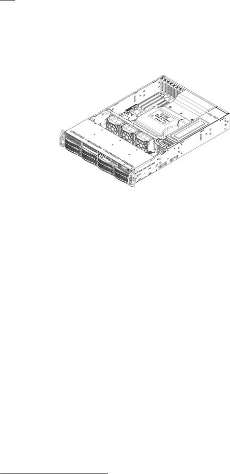
2 System overview
DIVAR IP 7000 is an affordable, simple and reliable all-in-one recording, viewing and management solution for network surveillance systems of up to 64 channels (with 32 channels pre-licensed). Running the full Bosch VMS (Video Management System) solution and powered by Bosch VRM (Video Recording Manager) software, the DIVAR IP 7000 is an intelligent IP storage device that eliminates the need for separate NVR (Network Video Recorder) server and storage hardware.
The 2U rack mount unit combines advanced management and state-of-the-art recording management into a single cost-effective, plug and play IP recording appliance for IT-minded customers which are seeking for a state-of-the-art “second generation” NVR recording solution.
DIVAR IP 7000 features:
–Instant real time access to video
View high quality HD video despite low or limited bandwidth connections. Dynamic Transcoding technology ensures that you can view your video immediately — anytime, anywhere.
–Easy installation
DIVAR IP 7000 2U features wizard based set-up and centralized configuration to reduce installation times. All components are pre-installed and pre-configured. Simply connect to the network and turn on the unit — DIVAR IP 7000 2U starts recording straight out of the box.
–Access to Bosch VMS
After starting the system, immediate access to the Bosch VMS management application is offered by a customized user interface. The ability to use one central user interface for configuration and operation management reduces installation and training requirements, and helps to keep ongoing system management costs low.
2.1 |
Chassis features |
The chassis includes the following features:
–CPU (Intel QuadCore)
–Internal SSD (80 GB) for operating system and application operations
–8 slots for U320 SCSI or SAS/SATA drives. These drives are hot swappable. Once setup correctly, these drives can be removed without powering down the server. In addition, these drives support SAF-TE (SCSI) and SES2 (SAS/SATA)
–Seven low-profile I/O expansion slots.
–Graphic card AMD V3900 (1x DVI, 1x Display Port output)
–Sound card
–One slim DVD-RW drive and one slim Floppy Drive. These drives allow you to quickly install or save data.
–One internal USB Transcoder device
Other onboard features are included to promote system health. These include various cooling fans, a convenient power switch, reset button, and LED indicators.
2.2 Chassis components
This chapter describes the most common components included with your chassis. For more information, see the installation instructions detailed later in this manual.
Bosch Sicherheitssysteme GmbH |
Installation Manual |
2014.12 | V4 | DOC |

10 en | System overview |
DIVAR IP 7000 2U |
|
|
2.2.1 Chassis
The chassis includes 8 hard drive bays and supports a 2U backplane, 3 fans and two power supplies.
2.2.2 Backplane
Each chassis comes with a 2U backplane. The backplane accepts SAS/SATA hard drives.
Warning!
Use caution when servicing and working around the backplane. Hazardous voltage or energy
!is present on the backplane when the system is operating. Do not touch the backplane with any metal objects and make sure no ribbon cables touch the backplane.
2.2.3 |
Fans |
|
The chassis supports 3 system fans that are powered from the motherboard. These fans are |
|
2U high and are powered by 3-pin connectors. |
2.2.4 |
Mounting rails |
|
The unit can be placed in a rack for secure storage and use. To setup your rack, follow the |
|
step-by-step instructions included in this manual. |
2.2.5 |
Power supply |
|
Each chassis model includes 2 high-efficiency power supplies (redundant). In the unlikely |
|
event your power supply fails, replacement is simple and can be accomplished without tools. |
2.2.6 |
Air shroud |
|
Air shrouds are shields, usually plastic, which conduct the airflow directly to where it is |
|
needed. Always use the air shroud included with your chassis. |
2.3 |
System interface |
There are several LEDs on the front and rear of the chassis. The LEDs show the over-all status of the system and the activity and health of specific components.
2014.12 | V4 | DOC |
Installation Manual |
Bosch Sicherheitssysteme GmbH |

DIVAR IP 7000 2U |
System overview | en 11 |
|
|
Front view:
|
1 |
2 |
3 |
4 |
5 |
6 |
7 |
1 |
Power Failure |
5 |
Power |
|
|
|
|
2 |
Overheat/Fan Fail |
6 |
Reset |
|
|
|
|
3 |
NIC1/NIC2 |
7 |
Power on/off |
|
|
|
|
4 |
HDD |
|
|
|
|
|
|
Rear view:
|
1 |
2 |
3 |
4 |
5 |
6 |
|
7 |
|
|
|
|
|
|
|||
|
1 |
2x mains connection 100 – 240 VAC, |
|
5 |
Monitor (VGA) |
|||
|
|
50 - 60 Hz |
|
|
|
|
Note: |
|
|
|
|
|
|
|
|
Do not use! |
|
|
|
|
|
|
|
|||
|
2 |
2x PS/2 (mouse and keyboard) |
|
6 |
2x NIC |
|||
|
|
|
|
|
|
|
|
|
|
3 |
2x USB |
|
|
|
7 |
Slots for: |
|
|
|
|
|
|
|
|
– 1x graphic card (1x Display Port, |
|
|
4 |
Serial interface COM1 |
|
|
|
|
||
|
|
|
|
|
|
1x DVI) – DVI port must be used |
||
|
|
|
|
|
|
|
|
|
|
|
|
|
|
|
|
|
for configuration |
|
|
|
|
|
|
|
– |
1x sound card |
|
|
|
|
|
|
|
– |
2x USB 2.0 |
|
|
|
|
|
|
|
|
|
2.3.1 |
Control panel buttons |
|
|
|
|
|
|
|
There are two push-buttons located on the front of the chassis. These are (in order from left to right) a reset button and a power on/off button.
Bosch Sicherheitssysteme GmbH |
Installation Manual |
2014.12 | V4 | DOC |
12 en | System overview DIVAR IP 7000 2U
|
– |
Reset: The reset button is used to reboot the system. |
|
– |
Power: The main power switch is used to apply or remove power from the power |
|
|
supply to the server system. Turning off system power with this button removes the main |
|
|
power but keeps standby power supplied to the system. Therefore, you must unplug |
|
|
system before servicing. |
2.3.2 |
Control panel LEDs |
|
|
The control panel located on the front of the chassis has LEDs to provide you with critical |
|
|
information related to different parts of the system. This section explains what each LED |
|
|
indicates. |
|
|
– |
Power failure: A flashing LED indicates a power failure in the power supply. |
|
– |
Overheat/fan fail: A flashing LED indicates a fan failure. |
|
|
When continuously on (not flashing) the LED indicates an overheat condition, which may |
|
|
be caused by cables obstructing the airflow in the system or the ambient room |
|
|
temperature being too warm. Check the routing of the cables and make sure all fans are |
|
|
present and operating normally. You should also check to make sure that the chassis |
|
|
covers are installed. Finally, verify that the heat sinks are installed properly. |
|
|
This LED will remain flashing or on as long as the fan failure/overheat condition exists. |
|
– |
NiC2: A flashing LED indicates network activity on GLAN2. |
|
– |
NIC1: A flashing LED indicates network activity on GLAN1. |
|
– |
HDD: A flashing LED indicates IDE channel activity in the SAS/SATA drive, SCSI |
|
|
drive, and/or DVD-ROM drive activity. |
|
– |
Power: Indicates power is being supplied to the system's power supply units. |
|
|
This LED should normally be illuminated when the system is operating. |
2.3.3 |
Drive carrier LEDs |
|
|
Your chassis uses SAS/SATA. |
|
SAS/SATA drives
Each SAS/SATA drive carrier has two LEDs.
2014.12 | V4 | DOC |
Installation Manual |
Bosch Sicherheitssysteme GmbH |

DIVAR IP 7000 2U |
System overview | en 13 |
|
|
–Green: Each Serial ATA drive carrier has a green LED. When illuminated, this green LED (on the front of the SATA drive carrier) indicates drive activity. A connection to the SATA backplane enables this LED to blink on and off when that particular drive is being accessed.
–Red: The red LED indicates a SAS/SATA drive failure. If one of the SAS/SATA drives fail, you should be notified by your system management software.
Bosch Sicherheitssysteme GmbH |
Installation Manual |
2014.12 | V4 | DOC |
14 en | Chassis setup and maintenance DIVAR IP 7000 2U
3 Chassis setup and maintenance
This chapter covers the steps required to install components and perform maintenance on the chassis.
Caution!
!Review the warnings and precautions listed in the manual before setting up or servicing this chassis.
See also:
–Safety precautions, page 5
–Rack precautions, page 24
–General system precautions, page 25
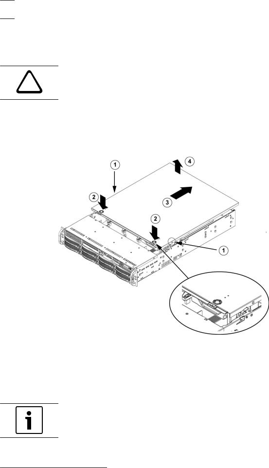
3.1 |
Removing the chassis cover |
To remove the chassis cover:
1.Remove the two screws on each side of the cover, which secure the cover to the chassis.
2.Press the release tabs to remove the cover from the locked position. Press both tabs at the same time.
3.Once the top cover is released from the locked position, slide the cover toward the rear of the chassis.
4.Lift the cover off the chassis.
Notice!
Except for short periods of time, do NOT operate the server without the cover in place. The chassis cover must be in place to allow proper airflow and prevent overheating.
2014.12 | V4 | DOC |
Installation Manual |
Bosch Sicherheitssysteme GmbH |
DIVAR IP 7000 2U Chassis setup and maintenance | en 15
3.2 |
Installing hard drives |
|
This chapter describes the removing and installing of hard drives. |
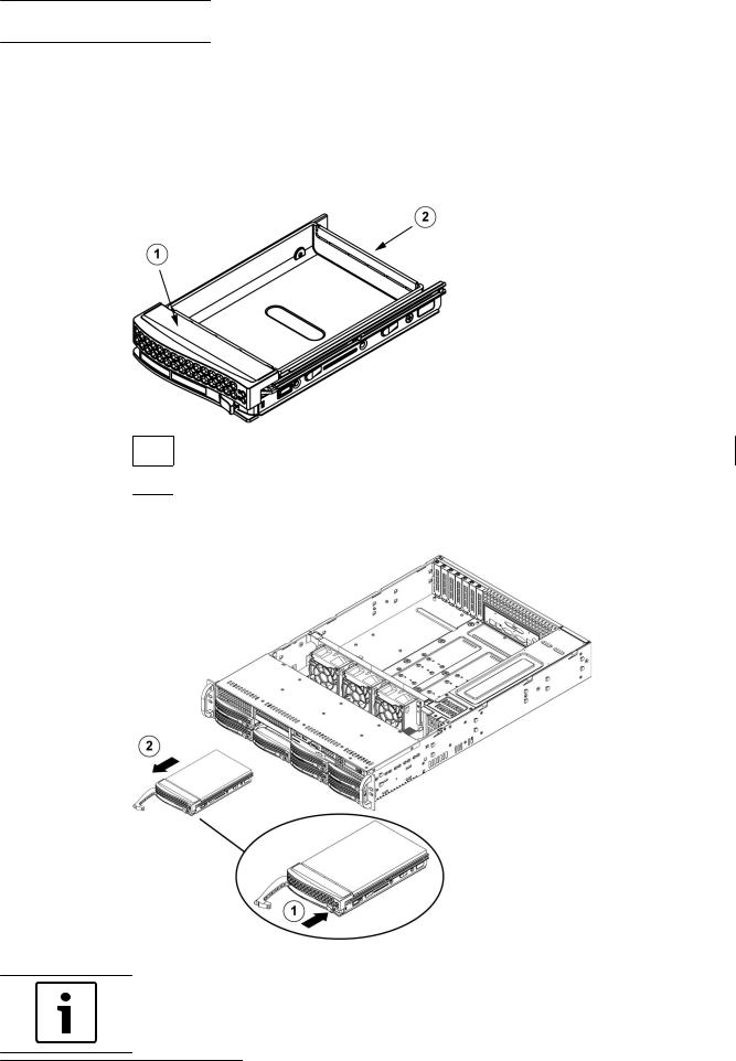
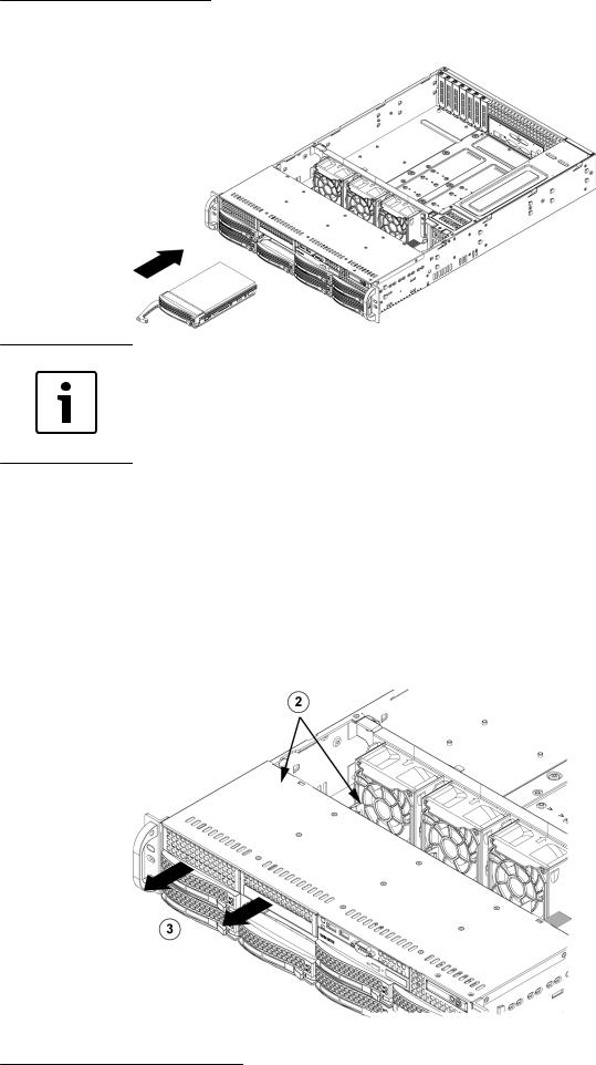
3.2.1 |
Removing hard drive trays |
|
The drives are mounted in drive carriers to simplify their installation and removal from the |
|
chassis. These carriers also help promote proper airflow for the drive bays. |
1 Drive carrier
2Dummy drive
To remove hard drive trays from the chassis:
1.Press the release button on the drive carrier. This extends the drive carrier handle.
2.Use the handle to pull the drive out of the chassis.
Notice!
Except for short periods of time (swapping hard drives), do not operate the unit with the hard drives removed from the bays.
Bosch Sicherheitssysteme GmbH |
Installation Manual |
2014.12 | V4 | DOC |
16 en | Chassis setup and maintenance |
DIVAR IP 7000 2U |
|
|
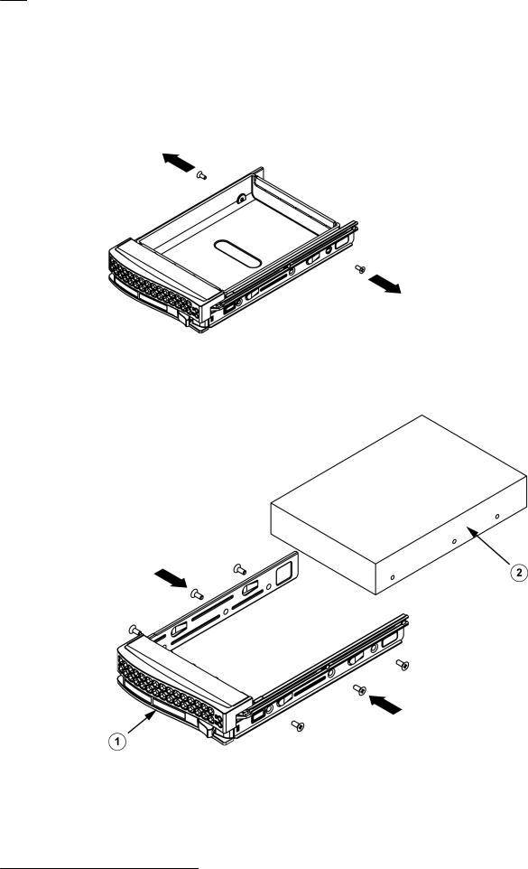
3.2.2 |
Installing a hard drive |
|
The drives are mounted in drive carriers. |
To install a hard drive to the hard drive carrier:
1.Remove the screws securing the dummy drive to the carrier.
2.Remove the dummy drive from the carrier.
3.Install a new drive into the carrier with the printed circuit board side facing down so that the mounting holes align with those in the carrier.
4.Secure the hard drive by tightening all 6 screws.
1 |
Drive carrier |
2 |
SAS/SATA hard drive |
|
|
|
|
5.Replace the drive carrier into the chassis bay. Make sure that the drive carrier handle is completely closed.
2014.12 | V4 | DOC |
Installation Manual |
Bosch Sicherheitssysteme GmbH |
DIVAR IP 7000 2U |
Chassis setup and maintenance | en 17 |
|
|
Notice!
We recommend using the respective Bosch hard disk drives. The hard disk drives as one of the critical component are carefully selected by Bosch based on available failure rates. HDD – not delivered from Bosch – are not supported. Information on supported HDDs can be found in the datasheet in the Bosch Online Product Catalog.
3.3 |
Installing a fixed hard drive |
|
|
The chassis models include two open slots for an optional floppy drive, and/or hard disk |
|
|
drive(s). To utilize these slots, the dummy drive and the slot cover must be removed. |
|
|
To remove the dummy drive or hard disk drive: |
|
|
1. |
Disconnect the chassis from any power source. |
|
2. |
Press the release tab. |
|
3. |
Push against the back of the dummy drive, sliding the dummy drive and slot cover |
|
|
forward, out through the front of the chassis. |
|
4. |
Insert the drive into rear of the open slot and connect the wiring. |
Bosch Sicherheitssysteme GmbH |
Installation Manual |
2014.12 | V4 | DOC |
18 en | Chassis setup and maintenance DIVAR IP 7000 2U
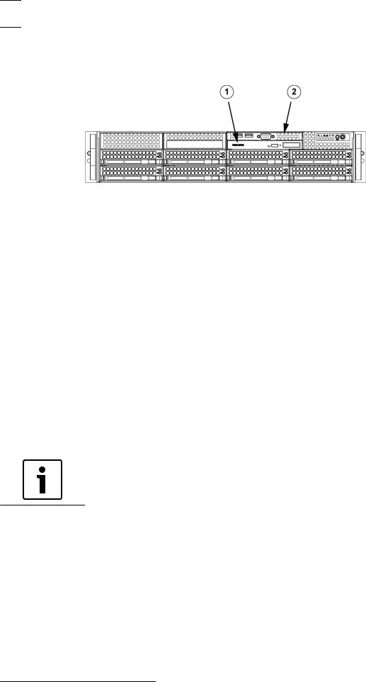
3.4 Replacing or installing a DVD-RW
The chassis model includes a pre-installed slim DVD-RW drive.
1 |
DVD-RW |
2 |
Front Port Panel |
|
|
|
|
To replace or install a DVD drive:
1.Power down the system and if necessary, remove the unit from the rack.
2.Remove the chassis cover.
3.Unplug the drives power and data cables from the motherboard and/or backplane.
4.If you are adding a new DVD drive:
Remove the mini-bezel (grate) from the drive bay The bezel can be removed by pulling out the hard drive beneath the DVD drive bay, then pulling the mini-bezel forward.
If you are replacing a drive:
Locate the locking tab at the rear (left hand side when viewed from the front) of the DVD drive. Push the tab toward the drive and push the drive unit out the front of the chassis.
5.Insert the new DVD drive in the slot until the tab locks in place.
6.Reconnect the data and power cables.
7.Replace the chassis cover (replace the unit in the rack, if necessary) and turn on the system.
3.5 |
Replacing the internal transcoder device |
|
The chassis model includes an internal USB transcoder device. |
|
|
|
Notice! |
|
To replace or install the transcoder device, please apply to one of the Bosch RMA helpdesks. |
3.6 |
Replacing or installing the front port panel |
|
The chassis model includes a front port panel. |
2014.12 | V4 | DOC |
Installation Manual |
Bosch Sicherheitssysteme GmbH |
DIVAR IP 7000 2U |
Chassis setup and maintenance | en 19 |
|
|
1 |
DVD-RW |
2 |
Front Port Panel |
|
|
|
|
To replace or install the front port panel:
1.Turn off and unplug the unit.
2.Remove the chassis cover.
3.Disconnect the power and data cables from the front port panel to other chassis components including the motherboard and backplane.
4.Remove the old port panel by depressing the release tab, then pulling the unit out of the chassis.
5.Insert the new front port panel unit in the slot until the tab locks into place.
6.Connect the data and power cables to the backplane and motherboard.
3.7 |
Installing the motherboard |
|
Motherboard problems will be handled by trained support people only. |
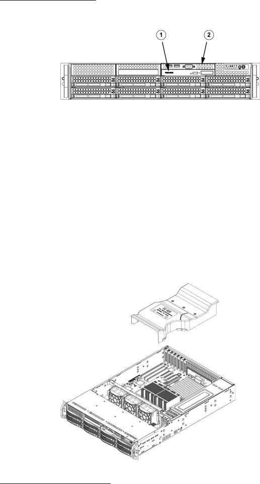
3.8 |
Installing the air shroud |
Air shrouds concentrate airflow to maximize fan efficiency. The air shroud does not require screws to set up.
Bosch Sicherheitssysteme GmbH |
Installation Manual |
2014.12 | V4 | DOC |
20 en | Chassis setup and maintenance |
DIVAR IP 7000 2U |
|
|
To install the air shroud:
4Place air shroud in the chassis. The air shroud fits behind the two fans closest to the power supply.
Note: If a 16 DIMM (13.68" x 13") motherboard is used, it is necessary to use the optional MCP-310-82502-0N air shroud.
|
See also: |
|
|
– |
Checking the air flow, page 20 |
3.9 |
Checking the air flow |
|
|
After installing the air shroud we recommend checking the air flow. |
|
|
To check the air flow: |
|
|
1. |
Make sure there are no objects to obstruct airflow in and out of the chassis. In addition, if |
|
|
you are using a front bezel, make sure the bezel's filter is replaced periodically. |
|
2. |
Do not operate the system without drives or drive trays in the drive bays. Use only |
|
|
recommended material. |
|
3. |
Make sure no wires or foreign objects obstruct air flow through the chassis. Pull all |
|
|
excess cabling out of the airflow path or use shorter cables. The control panel LEDs |
|
|
inform you about system status. |
|
See also: |
|
|
– |
Installing the air shroud, page 19 |
|
– |
System interface, page 10. |
|
– |
Installing the air shroud, page 19. |
|
– |
Rack installation, page 24. |
3.10 |
Replacing the system fans |
|
The system fans provide cooling for the chassis. These fans circulate air through the chassis as a means of lowering the chassis internal temperature.
2014.12 | V4 | DOC |
Installation Manual |
Bosch Sicherheitssysteme GmbH |
Loading...