


DKE665
a
de Gebrauchs- und
Montageanleitung
en Operating and
installation instructions
fr Mode d’emploi et
notice de montage
nl Gebruiksaanwijzing en
montagevoorschrift
it Istruzioni d’uso
e per il montaggio
es Instrucciones de uso
y de montaje
pt Instruções de serviçio
e de montagem
DKE 665A / 765A / 965A
Internet: http://www.bosch-hausgeraete.de
Bosch Info-Team: de Tel. 01 80/5 30 40 50 (E 0,12/Min. DTAG)
2
de
Seite 03–13
en
page 14 – 24
fr
pages 25 – 35
nl
pagina 36 – 46
it
pagina 47 – 57
es
página 58 – 68
pt
página 69 – 79
mind.
650
mind.
550
Abb. 1
ELEKTRO
ELECTR.
ELETT.
EL.
Abb. 1
GAS
GAZ
KAASU
GASS
3
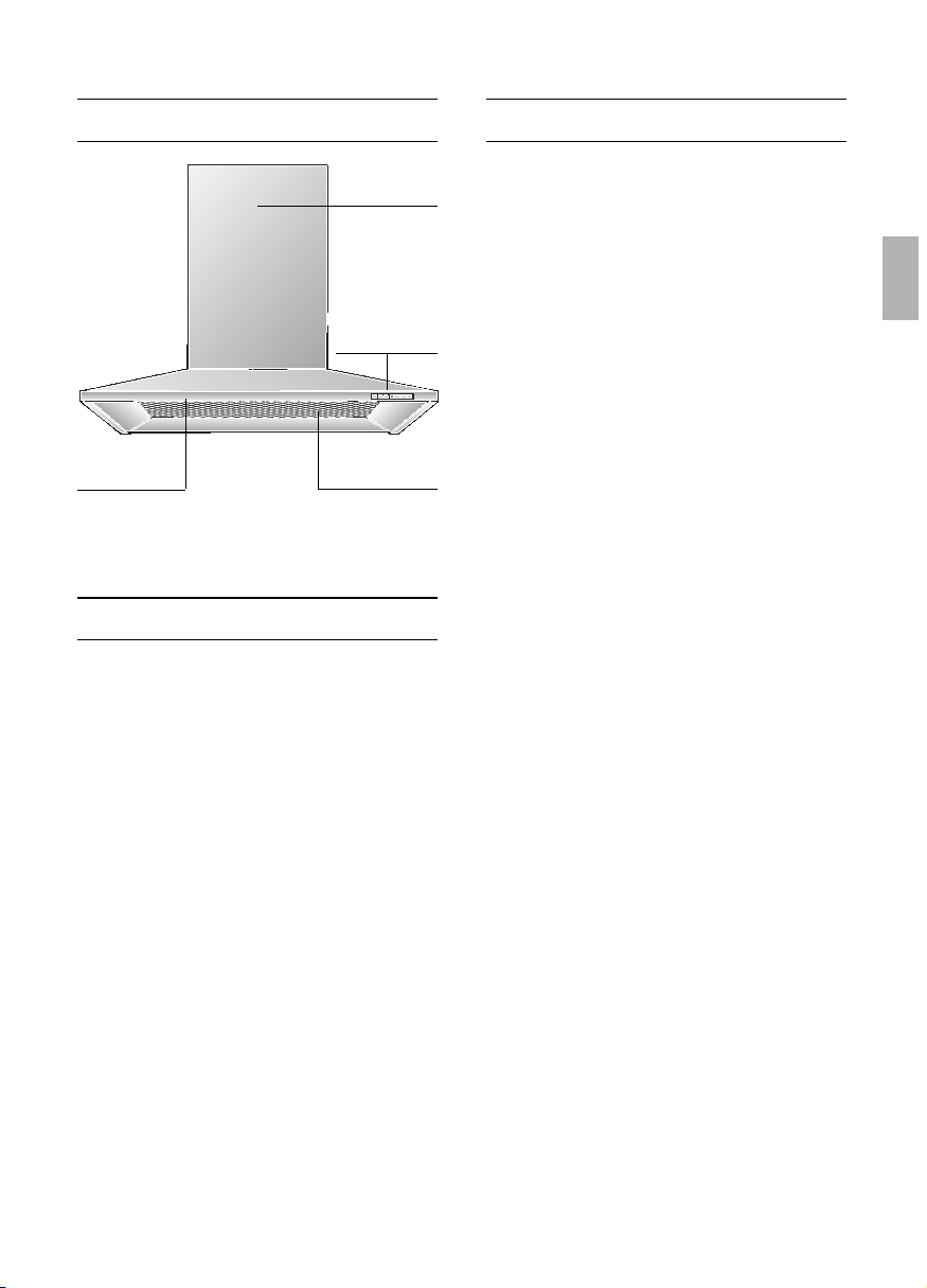
Gerätebeschreibung
Gebrauchsanleitung:
Betriebsarten
Betriebsarten
Abluftbetrieb:
❑ Der Lüfter der Dunstabzugshaube saugt
den Küchendunst an und leitet ihn durch
den Fettfilter ins Freie.
❑ Der Fettfilter nimmt die fettigen
Bestandteile des Küchendunstes auf.
❑ Die Küche bleibt weitgehend frei von
Fett und Geruch.
D
Bei Abluftbetrieb der Dunstabzugs-
haube und gleichzeitigem Betrieb
schornsteinabhängiger Feuerungen (wie
z. B. Gas-, Öl- oder Kohleheizgeräte,
Durchlauferhitzer, Warmwasserbereiter)
muss für ausreichend Zuluft gesorgt
werden, die von der Feuerstätte zur
Verbrennung benötigt wird.
Ein gefahrloser Betrieb ist möglich, wenn
der Unterdruck im Aufstellraum der
Feuerstätte von 4 Pa (0,04 mbar) nicht
überschritten wird.
Dies kann erreicht werden, wenn durch
nicht verschließbare Öffnungen, z.B. in
Türen, Fenstern und in Verbindung mit
Zuluft-/Abluftmauerkasten oder durch
andere techn. Maßnahmen, wie
gegenseitige Verriegelung o.ä., die
Verbrennungsluft nachströmen kann.
Bei nicht ausreichender Zuluft besteht
Vergiftungsgefahr durch zurückgesaugte
Verbrennungsgase.
Ein Zuluft-/Abluftmauerkasten allein stellt
die Einhaltung des Grenzwertes nicht
sicher.
Anmerkung: Bei der Beurteilung muss
immer der gesamte Lüftungsverbund der
Wohnung beachtet werden. Bei Betrieb von
Kochgeräten, z. B. Kochmulde und Gas-
herd wird diese Regel nicht angewendet.
Wenn die Dunstabzugshaube im Umluftbe-
trieb – mit Aktivkohlefilter – verwendet wird,
ist der Betrieb ohne Einschränkung
möglich.
Umluftbetrieb:
❑ Hierzu muss ein Aktivkohlefilter
eingebaut werden (siehe Filter und
Wartung).
Das komplette Montage-Set sowie
die Ersatzfilter können Sie beim
Fachhandel erwerben.
Die entsprechenden Zubehör-Nummern
finden Sie am Ende dieser Gebrauchs-
anleitung.
❑ Der Lüfter der Dunstabzugshaubesaugt
den Küchendunst an und leitet ihn durch
den Fett- und Aktivkohlefilter gereinigt in
die Küche zurück.
❑ Der Fettfilter nimmt die fettigen
Bestandteile des Küchendunstes auf.
❑ Der Aktivkohlefilter bindet die
Geruchsstoffe.
Wird kein Aktivkohlefilter eingebaut,
können keine Geruchsstoffe des
Küchendunstes gebunden werden.
Beleuchtung
Schalter
Licht/Lüfter
Filtergitter
Kamin-
verblendung

4
Störungen
Bei eventuellen Rückfragen oder
Störungen, Kundendienst anrufen.
(Siehe Kundendienststellenverzeichnis).
Bei Anruf bitte angeben:
E-Nr. FD
Tragen Sie die Nummern in obige Felder
ein. Die Nummern sind auf dem
Typenschild, nach Abnahme der Fettfilter,
im Innenraum der Dunstabzugshaube zu
finden.
Vor dem ersten Benutzen
Wichtige Hinweise:
❑ Diese Gebrauchsanleitung gilt für
mehrere Geräte-Ausführungen.
Es ist möglich, dass einzelne
Ausstattungsmerkmale beschrieben
sind, die nicht auf Ihr Gerät zutreffen.
❑ Diese Dunstabzugshaube entspricht den
einschlägigen Sicherheitsbestimmungen.
Reparaturen dürfen nur von Fachkräften
durchgeführt werden.
Durch unsachgemäße Reparaturen
können erhebliche Gefahren für den
Benutzer entstehen.
Die Kochstellen müssen immer mit
Kochgeschirr abgedeckt sein.
Über einer Feuerstätte für feste
Brennstoffe (Kohle, Holz und dgl.) ist der
Betrieb der Dunstabzugshaube nur bedingt
gestattet (siehe Montageanleitung).
Gas-Kochmulden / Gas-Herde
Betreiben Sie nicht alle Gas-
Kochstellen gleichzeitig über längere Zeit
(max. 15 Minuten) bei höchster
Wärmebelastung, sonst besteht
Verbrennungsgefahr bei Berührung der
Gehäuseoberflächen bzw. Gefahr der
Beschädigung der Dunstabzugshaube.
Beim Betrieb der Dunstabzugshaube über
einem Gas-Kochfeld muss bei gleich-
zeitigem Betreiben von drei oder mehr
Gas-Kochstellen die Haube in der
Maximalstufe betrieben werden.
❑ Bevor Sie das neue Gerät benutzen,
lesen Sie bitte sorgfältig die
Gebrauchsanleitung.
Sie enthält wichtige Informationen für Ihre
Sicherheit sowie zum Gebrauch und zur
Pflege des Gerätes.
❑ Bewahren Sie die Gebrauchs- und
Montageanleitung ggf. für einen
Nachbesitzer gut auf.
Ist das Gerät beschädigt, dürfen Sie es
nicht in Betrieb nehmen.
Anschluss und Inbetriebnahme dürfen
nur von einem Fachmann durchgeführt
werden.
Wenn die Anschlussleitung dieses
Gerätes beschädigt wird, muss sie durch
den Hersteller oder seinen Kundendienst
oder eine ähnlich qualifizierte Person ersetzt
werden, um Gefährdung zu vermeiden.
Verpackungsmaterial ordnungsgemäß
entsorgen (siehe Montageanleitung).
Diese Dunstabzugshaube ist nur für
den Betrieb in Haushalten bestimmt.
Dunstabzugshaube nur mit
eingesetzten Lampen betreiben.
Defekte Lampen sollten sofort ersetzt
werden, um Überlastung der restlichen
Lampen zu vermeiden.
Dunstabzugshaube nie ohne Fettfilter
betreiben.
Überhitzte Fette oder Öle können sich
leicht entzünden.
Darum Speisen mit Fetten oder Ölen,
z. B. Pommes frites, nur unter Aufsicht
zubereiten.
Unter der Dunstabzugshaube nicht
flambieren.
Brandgefahr am Fettfilter durch
! aufsteigende Flammen.

5
Filter und Wartung
Fettfilter:
Zur Aufnahme der fettigen Bestandteile
des Küchendunstes sind Metall-
Fettfilter eingesetzt.
Die Filtermatten bestehen aus unbrenn-
barem Metall.
Achtung:
Bei zunehmender Sättigung mit fetthaltigen
Rückständen erhöht sich die
Entflammbarkeit und die Funktion der
Dunstabzugshaube kann beeinträchtigt
werden.
Wichtig:
Durch rechtzeitiges Reinigen der Metall-
Fettfilter wird der Brandgefahr vorgebeugt,
die durch Hitzestau beim Frittieren oder
Braten entstehen kann.
Reinigen der Metall-Fettfilter:
❑ Bei normalem Betrieb (täglich 1 bis 2
Stunden) müssen die Metall-Fettfilter
nach 8 bis 10 Wochen gereinigt werden.
❑ Das Reinigen kann in der Geschirrspül-
maschine erfolgen. Dabei ist eine leichte
Verfärbung möglich.
❑ Der Filter muss locker in der Geschirr-
spülmaschine liegen.
Er darf nicht eingeklemmt sein.
Wichtig:
Stark gesättigte Metall-Fettfilter nicht
zusammen mit Geschirr reinigen.
❑ Beim Reinigen von Hand, die Fettfilter in
heißer Spüllauge einweichen.
Danach abbürsten, gut ausspülen und
abtropfen lassen.
1
23
Einschalten:
❑
Schieben Sie den Schiebeschalter auf
die gewünschte Lüfterstufe.
Ausschalten:
❑
Schieben Sie den Schiebeschalter auf 0
zurück.
Intensivstufe:
Durch die Intensivstufe wird die höchste
Leistung erreicht. Sie wird kurzzeitig
benötigt.
❑
Schieben Sie den Schiebeschalter ganz
nach rechts.
Während des Betriebes in Intensivstufe
leuchtet der Steg am Schiebeschalter.
Beleuchtung:
❑
Die Beleuchtung kann zu jeder Zeit
verwendet werden, auch wenn der
Lüfter ausgeschaltet ist.
Der Küchendunst wird am
wirkungsvollsten beseitigt durch:
❑
Einschalten der Dunstabzugshaube
bei Kochbeginn.
❑
Ausschalten der Dunstabzugshaube
erst einige Minuten nach Kochende.
Bedienen der Dunstabzugshaube
1
23
Beleuchtung
Aus / Ein
Lüfterstufen
Intensivstufe
6
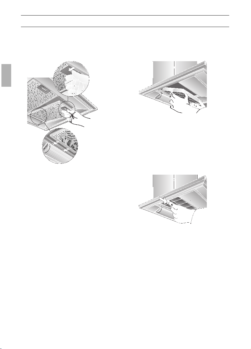
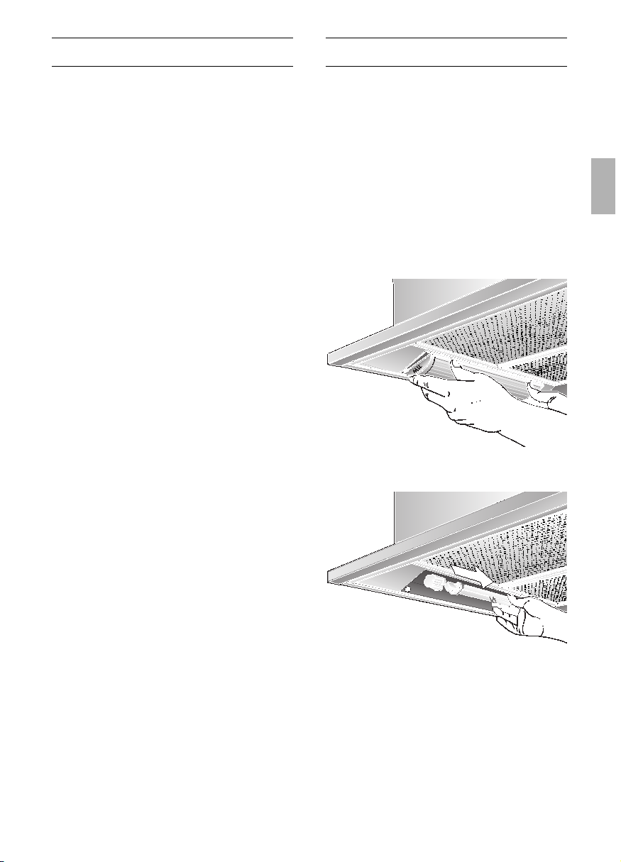
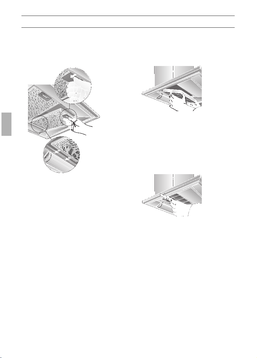
Aus- und Einbauen der Metall-Fettfilter:
1. Drücken Sie die Raste an den Fettfiltern
in Pfeilrichtung ein und klappen Sie die
Fettfilter ab.
Einbauen:
1. Bauen Sie die Fettfilter aus (siehe Aus-
und Einbauen der Metall-Fettfilter).
2. Setzen Sie den Aktivkohlefilter ein.
Filter und Wartung
3. Rasten Sie die Laschen auf beiden
Seiten ein.
4. Bauen Sie die Fettfilter ein (siehe Aus-
und Einbauen der Metall-Fettfilter).
Ausbauen:
1. Bauen Sie die Fettfilter aus.
2. Drücken Sie die Laschen auf beiden
Seiten ein und nehmen Sie den Aktiv-
kohlefilter nach unten ab.
2. Reinigen Sie die Fettfilter.
3. Setzen Sie die gereinigten Fettfilter
wieder ein.
Aktivkohlefilter:
Zum Binden der Geruchsstoffe beim
Umluftbetrieb.
Achtung:
Bei zunehmender Sättigung mit fetthaltigen
Rückständen erhöht sich die
Entflammbarkeit und die Funktion der
Dunstabzugshaube kann beeinträchtigt
werden.
Wichtig:
Durch rechtzeitigen Wechsel des
Aktivekohlefilters wird der Brandgefahr
vorgebeugt, die durch Hitzestau beim
Frittieren oder Braten entstehen kann.
3. Bauen Sie die Fettfilter ein.
Wechsel des Aktivkohlefilters:
❑ Bei normalem Betrieb (täglich 1 bis 2
Stunden) müssen die Aktivkohlefilter
ungefähr 1 x im Jahr ausgetauscht
werden.
❑ Der Aktivkohlefilter ist im Fachhandel
erhältlich (siehe Sonderzubehör).
❑ Nur Originalfilter verwenden.
Dadurch wird die optimale Funktion
gewährleistet.
Entsorgung des alten Aktivkohlefilters:
❑ Aktivkohlefilter enthalten keine
Schadstoffe. Sie können z. B. als
Restmüll entsorgt werden.
7
Reinigen und Pflegen
Dunstabzugshaube durch Ziehen des
Netzsteckers bzw. Ausschalten der
Sicherung stromlos machen.
❑ Beim Reinigen der Fettfilter die
zugänglichen Gehäuseteile von
abgelagertem Fett reinigen.
Dadurch wird der Brandgefahr
vorgebeugt und die optimale Funktion
bleibt erhalten.
❑ Zum Reinigen der Dunstabzugshaube
heiße Spüllauge oder mildes Fenster-
putzmittel verwenden.
❑ Kratzen Sie angetrocknete Ver-
schmutzung nicht ab, sondern weichen
Sie diese mit einem feuchten Tuch auf.
❑ Keine scheuernden Mittel oder
kratzende Schwämme verwenden.
❑ Hinweis: Alkohol (Spiritus) nicht auf
Kunststoffflächen anwenden, es
könnten matte Stellen entstehen.
Vorsicht! Küche ausreichend
belüften, keine offene Flamme.
Den Schiebeschalter nur mit einem
weichen, feuchten Tuch reinigen (milde
Spüllauge).
Keinen Edelstahlreiniger für den Schiebe-
schalter verwenden.
Edelstahloberflächen:
❑ Verwenden Sie einen milden nicht
scheuernden Edelstahlreiniger.
❑ Reinigen Sie nur in Schliffrichtung.
Edelstahloberflächen nicht mit
kratzenden Schwämmen und nicht mit
sand-, soda-, säure- oder chloridhaltigen
Putzmitteln reinigen!
Aluminium-, Lack- und Kunststoff-
oberflächen:
❑ Verwenden Sie ein weiches, fusselfreies
Fenster- oder Microfasertuch.
❑ Keine trockenen Tücher verwenden.
❑ Verwenden Sie ein mildes Fenster-
reinigungsmittel.
❑ Keine aggressiven, säure- oder laugen-
haltigen Reiniger verwenden.
❑ Keine Scheuermittel verwenden.
Auswechseln der Lampen
4. Setzen Sie die Lampenabdeckung
wieder ein.
5. Stellen Sie durch Einstecken des
Netzsteckers oder durch Einschalten der
Sicherung die Stromversorgung wieder
her.
1. Schalten Sie die Dunstabzugshaube aus
und machen Sie durch Ziehen des
Netzsteckers oder Ausschalten der
Sicherung die Dunstabzugshaube
stromlos.
2. Drücken Sie die Lampenabdeckung an
den beiden Laschen leicht zusammen
und nehmen Sie die Lampenabdeckung
nach unten ab.
3. Tauschen Sie die Lampe aus
(handelsübliche Leuchtstofflampe
max. 11 Watt, Sockel G 23).
Achtung: Steckfassung.

8
Montageanleitung:
Wichtige Hinweise
Zusätzliche Hinweise bei Gas-Koch-
geräten:
Bei der Montage von Gaskochstellen
sind die national einschlägigen gesetzlichen
Bestimmungen (z. B. in Deutschland:
Technische Regeln Gasinstallation TRGI) zu
beachten.
Es müssen die jeweils gültigen Einbau-
vorschriften und die Einbauhinweise der
Gas-Gerätehersteller beachtet werden.
Die Dunstabzugshaube darf nur an
einer Seite neben einem Hochschrank oder
einer hohen Wand eingebaut werden.
Abstand mind. 50 mm.
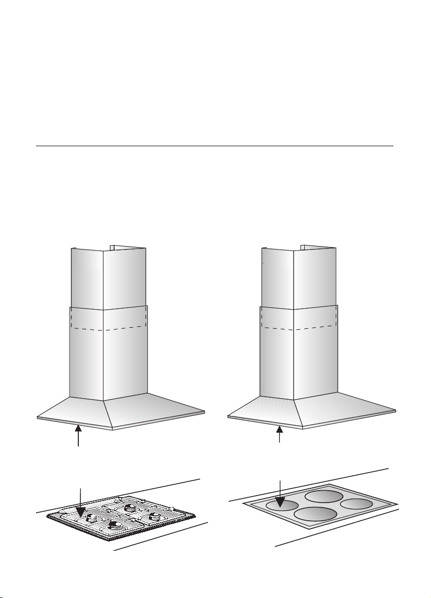
Mindestabstand bei Gas-Kochstellen
zwischen Oberkante Topfträger und
Unterkante der Dunstabzugs-
haube: 650 mm, Abb. 1.
Altgeräte sind kein wertloser Abfall.
Durch umweltgerechte Entsorgung können
wertvolle Rohstoffe wiedergewonnen
werden.
Bevor Sie das Altgerät entsorgen, machen
Sie es unbrauchbar.
Ihr neues Gerät wurde auf dem Weg zu
Ihnen durch die Verpackung geschützt. Alle
eingesetzten Materialien sind umweltver-
träglich und wieder verwertbar. Bitte helfen
Sie mit und entsorgen Sie die Verpackung
umweltgerecht.
Über aktuelle Entsorgungswege informieren
Sie sich bitte bei Ihrem Fachhändler oder
bei Ihrer Gemeindeverwaltung.
Die Dunstabzugshaube ist für Abluft-
und Umluftbetrieb verwendbar.
Die Dunstabzugshaube immer über der
Mitte der Kochstellen anbringen.
Mindestabstand zwischen Elektro-
kochstellen und Unterkante der Dunstab-
zugshaube: 550 mm, Abb. 1.
Über einer Feuerstätte für feste
Brennstoffe, von der eine Brandgefahr
(z. B. Funkenflug) ausgehen kann, ist die
Montage der Dunstabzugshaube nur dann
zulässig, wenn die Feuerstätte eine
geschlossene nicht abnehmbare
Abdeckung hat und die länderspezifischen
Vorschriften eingehalten werden.
Diese Einschränkung gilt nicht für Gas-
Herde und Gas-Mulden.
Je kleiner der Abstand zwischen
Dunstabzugshaube und Kochstellen desto
größer ist die Möglichkeit, dass sich durch
aufsteigenden Wasserdampf unten an der
Dunstabzugshaube Tropfen bilden können.

9
Vor der Montage
Die Abluft wird über einen Lüftungsschacht
nach oben, oder direkt durch die Außen-
wand ins Freie geleitet.
D
Die Abluft darf weder in einen in Betrieb
befindlichen Rauch- oder Abgaskamin
noch in einen Schacht, welcher der Ent-
lüftung von Aufstellungsräumen von Feuer-
stätten dient, abgegeben werden.
Bei der Ableitung von Abluft sind die
behördlichen und gesetzlichen Vor-
schriften (z. B. Landesbauordnungen) zu
beachten.
Bei Abführung der Luft in nicht in Betrieb
befindliche Rauch- oder Abgaskamine ist
die Zustimmung des zuständigen Schorn-
steinfegermeisters einzuholen.
D
Bei Abluftbetrieb der Dunstabzugs-
haube und gleichzeitigem Betrieb
schornsteinabhängiger Feuerungen (wie
z. B. Gas-, Öl- oder Kohleheizgeräte,
Durchlauferhitzer, Warmwasserbereiter)
muss für ausreichend Zuluft gesorgt
werden, die von der Feuerstätte zur Ver-
brennung benötigt wird.
Ein gefahrloser Betrieb ist möglich, wenn
der Unterdruck im Aufstellraum der
Feuerstätte von 4 Pa (0,04 mbar) nicht
überschritten wird.
Dies kann erreicht werden, wenn durch
nicht verschließbare Öffnungen, z.B. in
Türen, Fenstern und in Verbindung mit
Zuluft-/Abluftmauerkasten oder durch
andere techn. Maßnahmen, wie gegenseiti-
ge Verriegelung o.ä., die Verbrennungsluft
nachströmen kann.
Bei nicht ausreichender Zuluft besteht
Vergiftungsgefahr durch zurückgesaugte
Verbrennungsgase.
Ein Zuluft-/Abluftmauerkasten allein stellt
die Einhaltung des Grenzwertes nicht
sicher.
Anmerkung: Bei der Beurteilung muss
immer der gesamte Lüftungsverbund der
Wohnung beachtet werden. Bei Betrieb
von Kochgeräten, z. B. Kochmulde und
Gasherd wird diese Regel nicht
angewendet.
Wenn die Dunstabzugshaube im Umluftbe-
trieb – mit Aktivkohlefilter – verwendet wird,
ist der Betrieb ohne Einschränkung
möglich.
Wird die Abluft durch die Außenwand
geleitet, sollte ein Teleskop-Mauerkasten
verwendet werden.
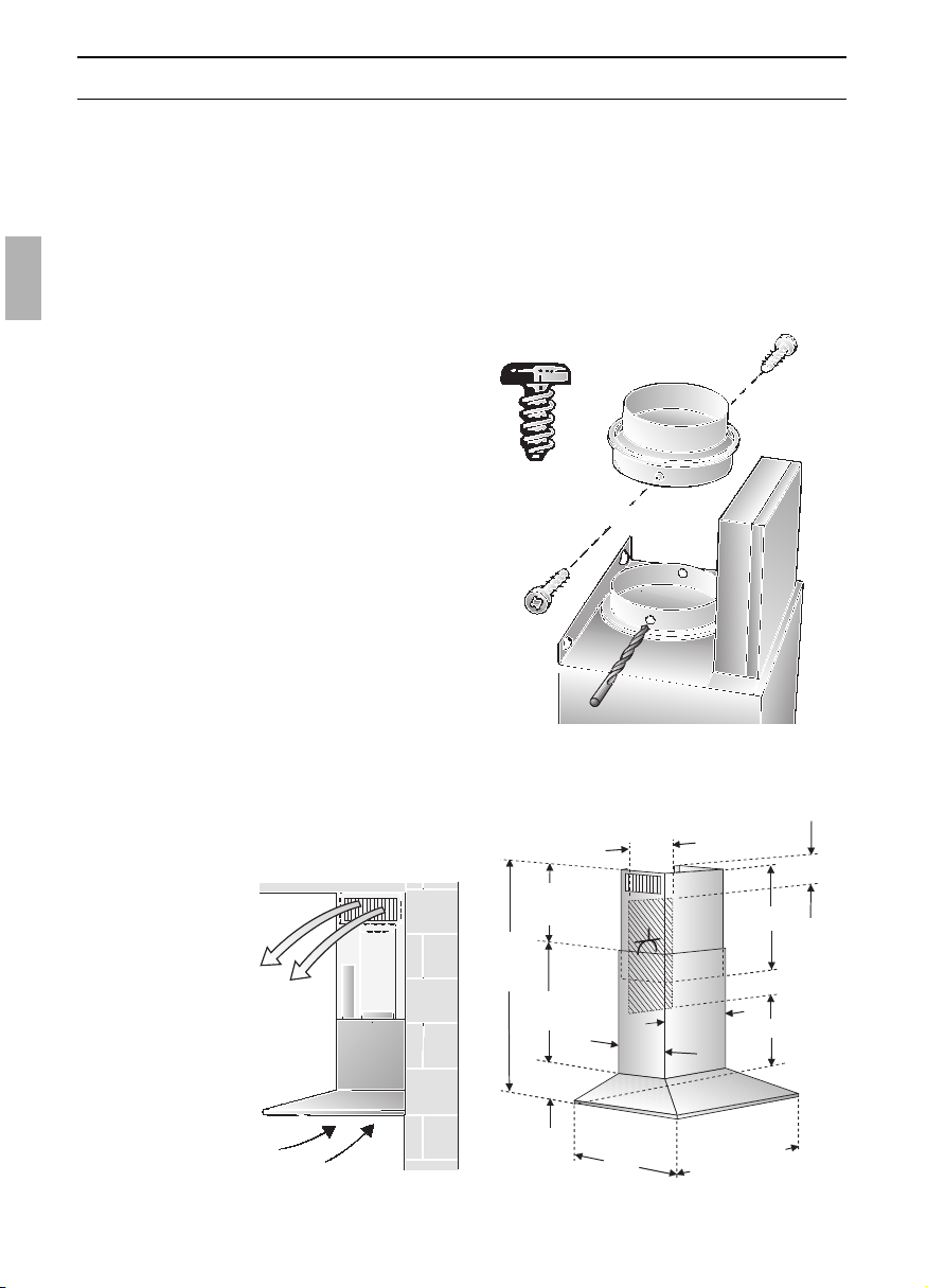
Abluftbetrieb
120
150
120
150
mind. 45
700-1105
250
350
580
520
600/
700/
900
90
130
565
mind.550
mind.40
3
1
5
10
Vor der Montage
Optimale Leistung der Dunstabzugs-
haube:
❑ Kurzes, glattes Abluftrohr.
❑ Möglichst wenig Rohrbögen.
❑ Möglichst große Rohrdurchmesser und
große Rohrbögen.
Der Einsatz von langen, rauhen
Abluftrohren, vielen Rohrbögen oder
kleineren Rohrdurchmessern führt zu
einer Abweichung von der optimalen
Luftleistung und gleichzeitig zu einer
Geräuscherhöhung.
❑ Rundrohre:
Wir empfehlen
Innendurchmesser 150 mm, jedoch
mind. 120 mm.
❑ Flachkanäle müssen einen gleichwer-
tigen Innenquerschnitt wie Rundrohre
haben.
Sie sollten keine scharfen Umlenkun-
gen haben.
l 120 mm ca. 113 cm
2
l 150 mm ca. 177 cm
2
❑ Bei abweichenden Rohrdurch-
messern: Dichtstreifen einsetzen.
❑ Bei Abluftbetrieb für ausreichend Zuluft
sorgen.
Umluftbetrieb
❑ Mit Aktivkohlefilter, wenn keine
Möglichkeit für Abluftbetrieb vorhanden
ist.
Anschluss Abluftrohr l 150 mm:
❑ Abluftrohr direkt am Luftstutzen
befestigen.
Anschluss Abluftrohr l 120 mm:
❑ Reduzierstutzen in den Luftstutzen
einsetzen, 2 Löcher l 3 mm vorbohren
und verschrauben.
775-
1220
mind.
120
250
3
5
0
580
520
6
0
0
/
7
0
0
/
9
0
0
90
565
mind.550
mind.120
315
❑ Abluftrohr am Reduzierstutzen
befestigen.
Das komplette
Montage-Set
können Sie beim
Fachhandel
erwerben.
Die entsprechen-
den Zubehör-
Nummern finden
Sie auf der letzten
Seite.
11
Vorbereiten der Wand
❑ Die Wand muss eben und senkrecht
sein.
❑ Bei Geräten mit Beleuchtung hinten:
Wird direkt unter die Dunstabzugshaube
an die Wand eine Nischenverkleidung
montiert oder Fliesen verlegt, darf der
Vorsprung max. 15 mm betragen, um
eine Beschädigung der Lampenab-
deckung zu vermeiden.
❑ Für festen Halt der Dübel ist zu sorgen.
Gewicht in kg:
Vor der Montage Elektrischer Anschluss
Die Dunstabzugshaube darf nur an eine
vorschriftsmäßig installierte Schutzkontakt-
steckdose angeschlossen werden.
Die Schutzkontaktsteckdose möglichst
direkt hinter der Kaminverblendung
anbringen.
Elektrische Daten:
Sie sind auf dem Typenschild nach
Abnahme der Filterrahmen – im Innenraum
des Gerätes – zu finden.
Bei Reparaturen die Dunstabzugs-
haube generell stromlos machen.
Länge der Anschlussleitung: 1,30 m.
Bei erforderlichem Festanschluss:
Die Dunstabzugshaube darf in jedem Fall
nur durch einen beim zuständigen
Elektrizitäts-Versorgungsunternehmen
eingetragenen Elektro-Installateur
angeschlossen werden.
Installationsseitig ist eine Trennvorrichtung
vorzusehen. Als Trennvorrichtung gelten
Schalter mit einer Kontaktöffnung von mehr
als 3 mm und allpoliger Abschaltung. Dazu
gehören LS-Schalter und Schütze.
Wenn die Anschlussleitung dieses
Gerätes beschädigt wird, muss sie durch
den Hersteller oder seinen Kundendienst
oder eine ähnlich qualifizierte Person
ersetzt werden, um Gefährdung zu
vermeiden.
Diese Dunstabzugshaube entspricht den
EG-Funkentstörbestimmungen.
Abluft Umluft
20,260 cm 22,4
21,570 cm 23,7
23,290 cm 25,4
Konstruktionsänderungen im Rahmen der technischen
Entwicklung bleiben vorenthalten.
12
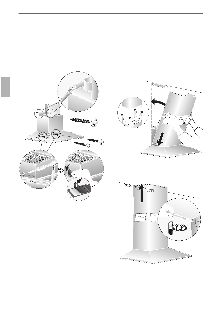
Einbauen
Hinweis: Achten Sie auf eventuell zu
montierende Sonderzubehörteile.
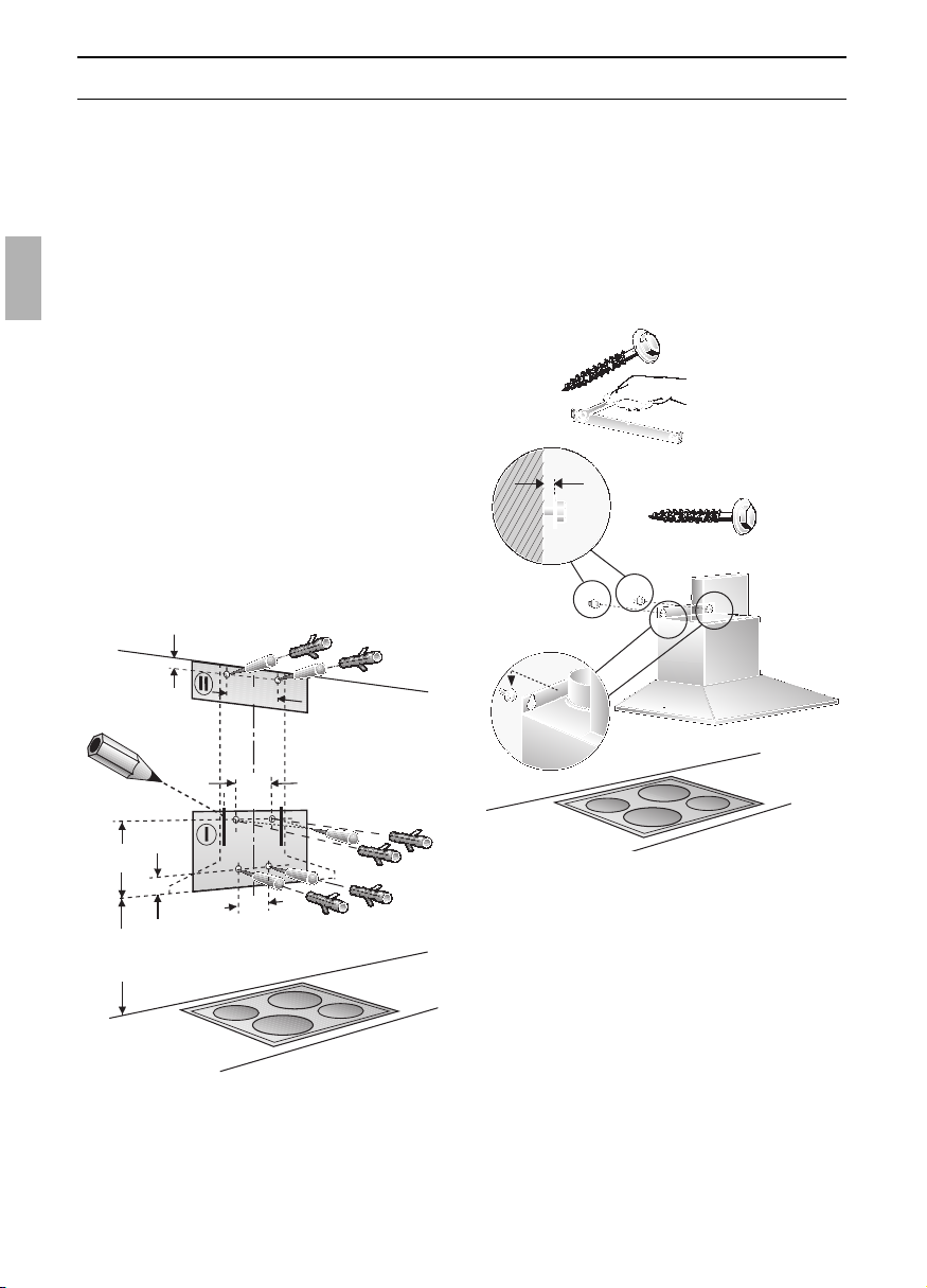
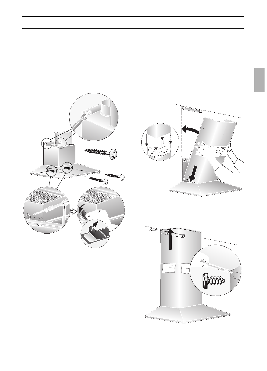
5. Haltewinkel für Kaminverblendung mit
2 Sechskantschrauben anschrauben.
6. Die beiden oberen Sechskant-
schrauben bis auf ca. 5 mm eindrehen.
7. Dunstabzugshaube an den Schrauben
einhängen.
ca.5mm
15
300
230
411
90
1
6
0
mind.550 Elektro
mind.650 Gas
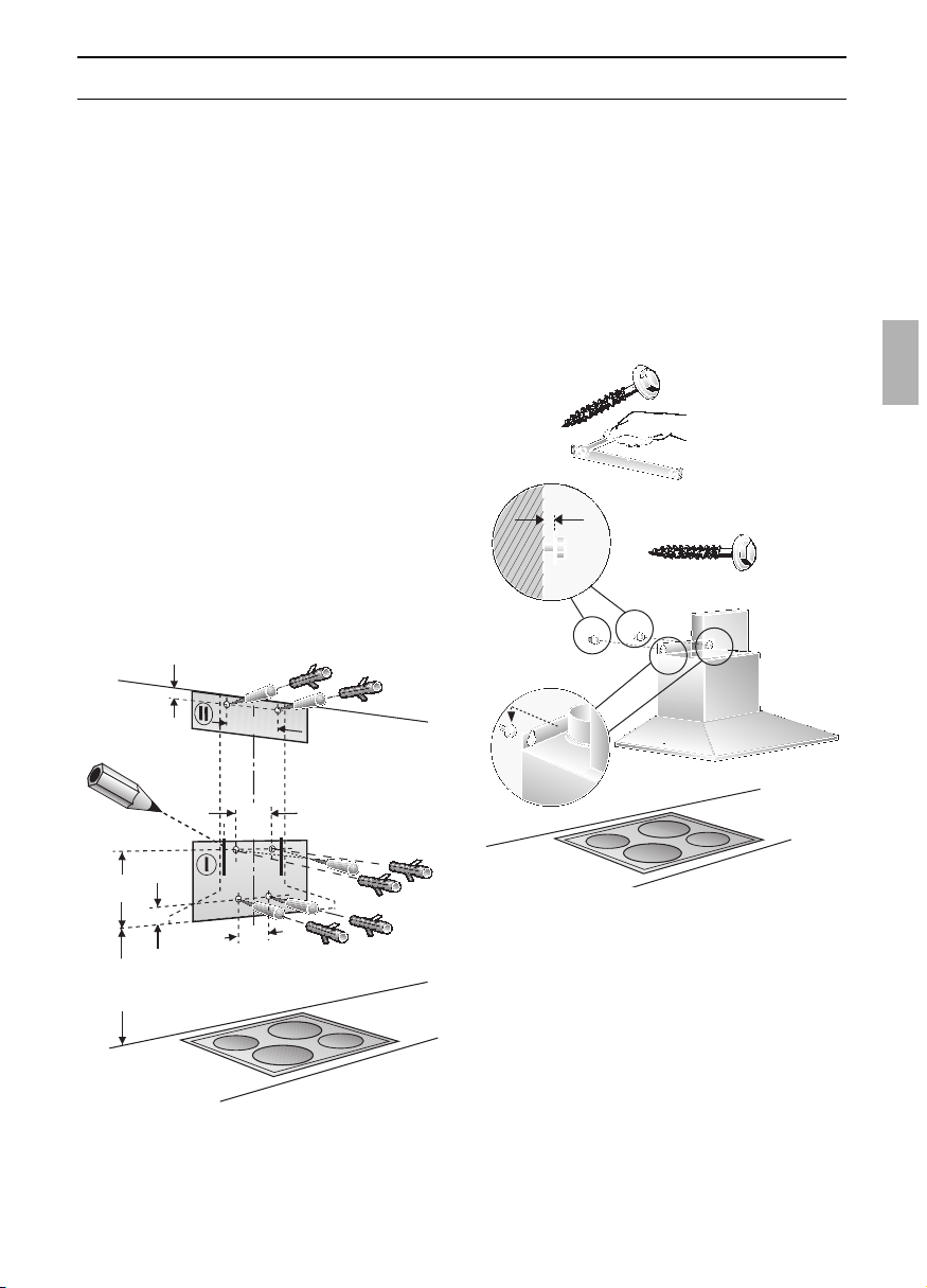
Die Dunstabzugshaube ist für die
Montage an die Küchenwand vorgesehen.
1. Fettfilter abnehmen
(siehe Gebrauchsanleitung).
2. Von der Decke bis zur Unterkante der
Dunstabzugshaube eine Mittellinie an
die Wand anzeichnen.
3. Mit Hilfe der Schablone Positionen für
die Schrauben an der Wand anreißen
und zum leichteren Einhängen die
Kontur des Einhängebereiches
anzeichnen.
Auf Mindestabstand Kochstelle –
Dunstabzugshaube von 550 mm bei
Elektro-Kochstellen bzw. 650 mm bei Gas-
Kochstellen achten. Der untere Rand der
Schablone entspricht dem unteren Rand
der Dunstabzugshaube.
4. 4 Löcher für die Dunstabzugshaube und
2 Löcher für die Kaminverblendung
l 8 mm bohren und Dübel wandbündig
eindrücken.
13
Einbauen
08. Die beiden unteren Sechskant-
schrauben eindrehen.
Vor dem Festdrehen der
4 Schrauben ist die Dunstabzugs-
haube auszurichten.
09. Je eine Abdeckfolie über die Löcher der
2 unteren Befestigungsschrauben auf
das Schutzgitter kleben.
13. Die beiden Teile der Kaminverblendung
ineinander schieben (Schlitze am obe-
ren Teleskopteil nach unten) und in den
Ausschnitt an der Dunstabzugshaube
einsetzen.
Vermeiden Sie Kratzer beim
Ineinanderschieben, in dem Sie z. B.
die Montageschablone als Schutz über
die Kante der unteren Kaminverblen-
dung legen.
10. Rohrverbindung herstellen.
11. Elektrische Verbindung herstellen.
12. Schutzfolie an den beiden
Kaminverblendungen abziehen.
Vermeiden Sie Beschädigungen der
empfindlichen Edelstahloberflächen.
1.
2.
15. Fettfilter wieder einsetzen (siehe
Gebrauchsanleitung).
1.
2.
3.
14. Den oberen Teil anheben und mit
2 Schrauben seitlich an den
Haltewinkel schrauben.

14
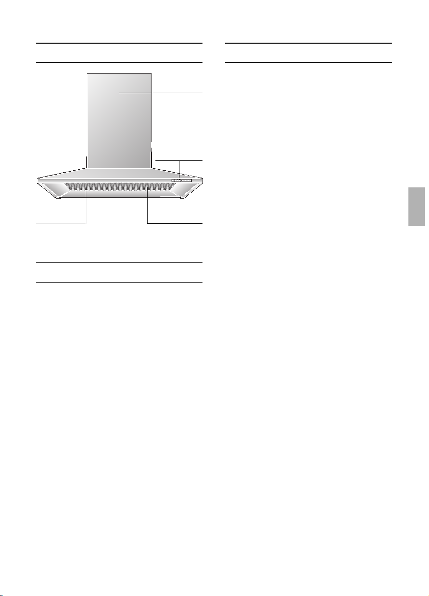
Appliance description
Instructions for use:
Lighting
Light / fan
switches
Filter grille
Chimney
panelling
Operating modes
Exhaust-air mode:
❑ The extractor-hood fan extracts the
kitchen vapours and conveys them
through the grease filter into the
atmosphere.
❑ The grease filter absorbs the solid
particles in the kitchen vapours.
❑ The kitchen is kept almost free of grease
and odours.
D
When the extractor hood is operated
in exhaust-air mode simultaneously with
a different burner which also makes use
of the same chimney (such as gas, oil or
coal-fired heaters, continuous-flow heaters,
hot-water boilers) care must be taken to
ensure that there is an adequate supply
of fresh air which will be needed by the
burner for combustion.
Safe operation is possible provided that the
underpressure in the room where the
burner is installed does not exceed 4 Pa
(0.04 mbar).
Operating modes
This can be achieved if combustion air can
flow through non-lockable openings, e.g. in
doors, windows and via the air-
intake/exhaust-air wall box or by other
technical measures, such as reciprocal
interlocking, etc.
If the air intake is inadequate, there is a
risk of poisoning from combustion gases
which are drawn back into the room.
An air-intake/exhaust-air wall box by itself is
no guarantee that the limiting value will not
be exceeded.
Note: When assessing the overall
requirement, the combined ventilation
system for the entire household must be
taken into consideration. This rule does not
apply to the use of cooking appliances,
such as hobs and ovens.
Unrestricted operation is possible if the
extractor hood is used in recirculating mode
– with activated carbon filter.
Circulating-air mode:
❑ An activated carbon filter must be fitted
for this operating mode (see Filters and
maintenance).
The complete installation set and
replacement filters can be obtained from
specialist outlets.
The corresponding accessory numbers
can be found at the end of these
operating instructions.
❑ The extractor-hood fan extracts the
kitchen vapours which are purified in the
grease filter and activated carbon filter
and then conveyed back into the
kitchen.
❑ The grease filter absorbs the grease
particles in the kitchen vapours.
❑ The activated carbon filter binds the
odorous substances.
If no activated carbon filter is installed,
it is not possible to bind the odorous
substances in the cooking vapours.

Before using for the first time
If you encounter a problem
If you have any questions or if a fault
occurs, please call Customer Service.
(See list of Customer Service
representatives).
When you call, please quote the following:
E-Nr. FD
Enter the relevant numbers into the box
above. The E-Nr. (product no.) and FD
(production date) are shown on the
nameplate which can be seen inside the
extractor hood after the filter frame has
been detached.
Important notes:
❑ The Instructions for Use apply to several
versions of this appliance. Accordingly,
you may find descriptions of individual
features that do not apply to your
specific appliance.
❑ This extractor hood complies with all
relevant safety regulations.
Repairs should be carried out by
qualified technicians only.
Improper repairs may put the user at
considerable risk.
❑ Before using your appliance for the first
time, please read these Instructions for
Use carefully. They contain important
information concerning your personal
safety as well as on use and care of the
appliance.
❑ Please retain the operating and
installation instructions for a subsequent
owner.
Do not use the appliance if damaged.
The appliance may be connected to the
mains by a qualified technician only.
The appliance is not intended for use by
young children or infirmed persons
without supervision.
Young children should be supervised to
ensure they do not play with the appliance.
If the connecting cable for this
appliance is damaged, the cable must be
replaced by the manufacturer or his customer
service or a similarly qualified person in order
to prevent serious injury to the user.
Dispose of packaging materials
properly (see Installation instructions).
This extractor hood is designed for
domestic use only.
Light bulbs must always be fitted when
the extractor hood is in use.
Defective bulbs should be replaced
immediately to prevent the remaining bulbs
from overloading.
Never operate the extractor hood
without a grease filter.
Overheated fat or oil can easily catch fire.
If you are cooking with fat or oil, e.g. chips,
etc., never leave the cooker unattended.
Do not flambé food directly under the
extractor hood.
Risk of grease filter catching fire due
! to flames.
The hotplates must always be covered
with a utensil.
Restrictions apply to the use of the
extractor hood over a solid-fuel burner
(coal, wood, etc.). (See Installation
instructions).
Gas hobs / Gas cookers
Do not use all the gas hotplates
simultaneously for a prolonged period
(max. 15 minutes) at maximum thermal
load, otherwise there is a risk of burns if the
housing surfaces are touched or a risk of
damage to the extractor hood. If the
extractor hood is situated over a gas hob,
operate the hood at maximum setting if
three or more gas hotplates are operated
simultaneously.
15
16
Operating procedure
Filters and maintenance
Grease filters:
Metal filters are used to trap the greasy
element of the vapours that develop
during cooking.
The filter mats are made from non-
combustible metal.
Caution:
As the filter becomes more and more
saturated with grease, not only does the
risk of it catching fire increase but the
efficiency of the extractor hood can also be
adversely affected.
Important:
By cleaning the metal grease filters at
appropriate intervals, the possibility of them
catching fire as a result of a build-up of heat
such as occurs when deep-fat frying or
roasting is taking place, is reduced.
Cleaning the metal grease filters:
❑ In normal operation (1 to 2 hours daily),
the metal grease filter must be cleaned
after 8 to 10 weeks.
❑ The filters can be cleaned in a dish-
washer. It is however possible that they
will become slightly discoloured.
❑ The filter must be placed loosely, and
NOT wedged, in the dishwasher.
Important:
Metal filters that are saturated with
grease should not be washed together
with other dishes etc.
❑ When cleaning the filters by hand, soak
them in hot soapy water first of all.
Then brush the filters clean, rinse them
thoroughly and leave the water to drain off.
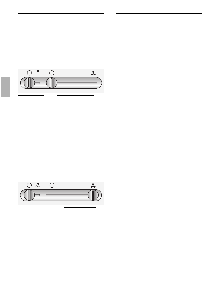
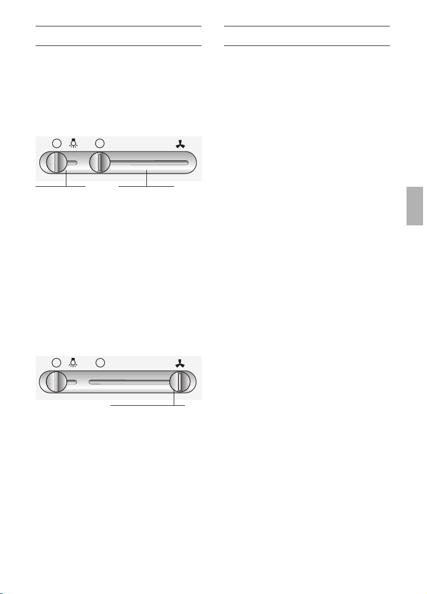
To switch ON:
❑
Push the sliding switch to the required
ventilator setting.
To switch OFF:
❑
Push the sliding switch back to 'O'.
Intensive setting:
The intensive setting provides maximum
ventilating power. It is only required for short
periods of time.
❑
Push the sliding switch all the way
across to the right.
The ridge on the switch knob lights up
when the ventilator is operating on the
intensive setting.
Lighting:
❑
The light can be switched on at any
time, even though the fan is switched off.
The most effective method of removing
vapours produced during cooking is to:
❑
Switch the ventilator ON
as soon as you begin cooking.
❑
Switch the ventilator OFF
a few minutes after you have finished
cooking.
1
23
Light
Off/On
Ventilator settings
1
23
Intensive setting
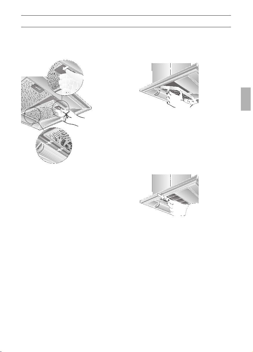
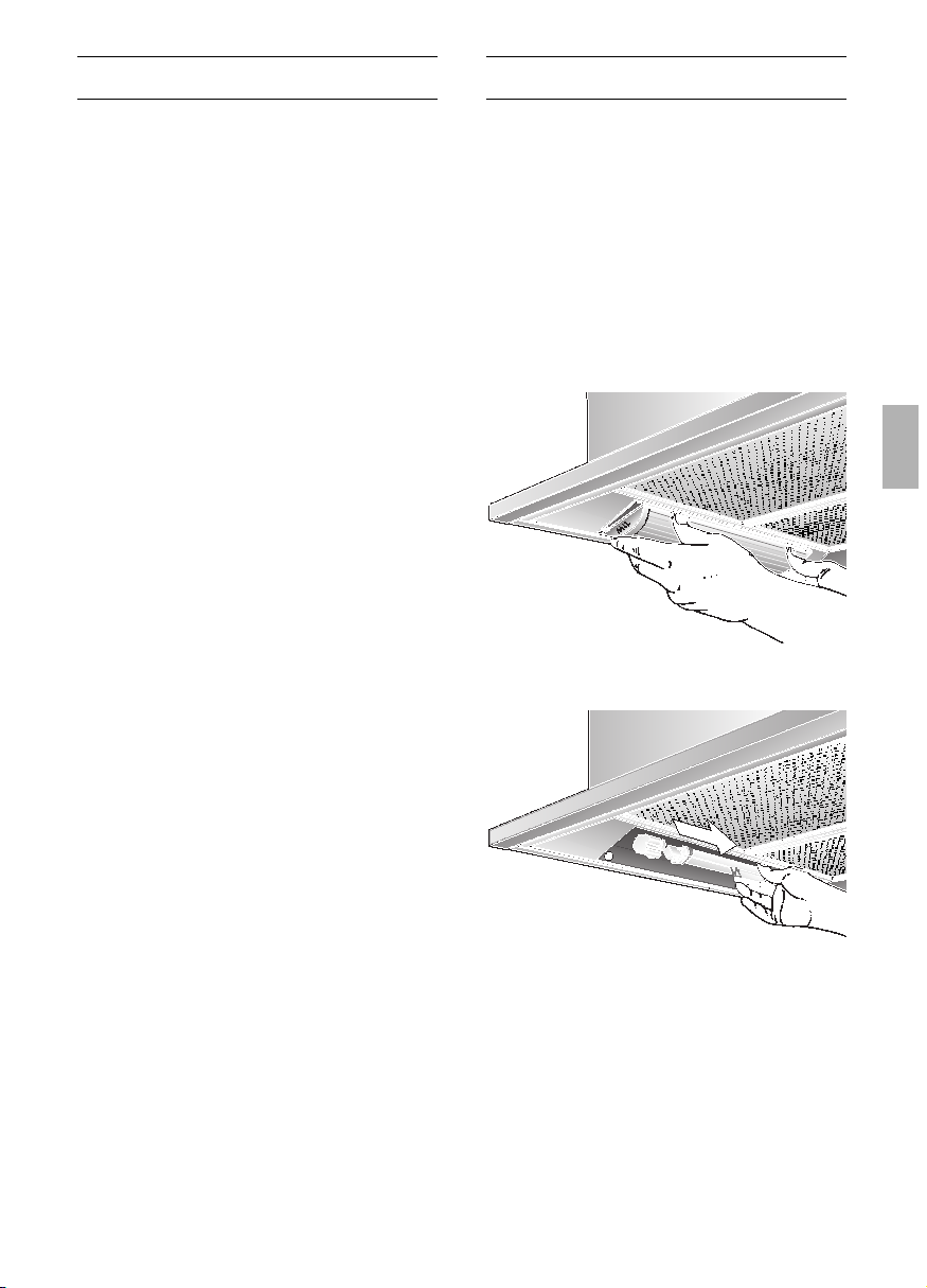
Removing and inserting the metal grease
filters:
1. Press the catch on the grease filters
inwards and fold the filters down.
Inserting the filter:
1. Remove the metal filters (see "Removing
and inserting the metal grease filters").
2. Insert the activated carbon filter.
Filters and maintenance
2. Clean the filters.
3. Insert the clean filters back into the
hood.
Activated carbon filter:
For neutralizing odours in recirculating
mode.
Caution:
As the filter becomes more and more
saturated with grease, there is an increased
risk of fire and the function of the extractor
hood may be impaired.
Important:
Change the activated carbon filter promptly
to prevent the risk of fire from the
accumulation of heat when deep-fat frying
or roasting.
3. Insert the metal grease filters.
Replacing the activated carbon filter:
❑ During normal operation (1 to 2 hours
per day) the activated carbon filters
should be replaced approximately 1 x
year.
❑ A replacement filter can be obtained
from any authorized dealer (see optional
accessories).
❑ Use original filters only.
By doing so you will obtain maximum
performance from your extractor hood.
Disposing of the old activated carbon
filter:
❑ There are no pollutants in the activated
carbon filters. They can therefore be
disposed of as part of your normal
domestic refuse.
3. Engage the catches at both sides.
4. Insert the metal grease filters (see
"Removing and inserting the metal
grease filters").
Removing the filter:
1. Remove the metal filters.
2. Press the catches at both sides of the
filter inwards and lift the carbon filter
down and out
17

18
Replacing the light bulbsCleaning and care
Disconnect the extractor hood from the
electricity supply by pulling out the
mains plug or switching it off at the fuse
box.
❑ At the same time as you clean the
grease filters, clean off any grease from
all accessible parts of the housing. This
significantly reduces the fire hazard and
ensures that the extractor hood
performs as effectively as possible.
❑ Use a hot detergent solution or a mild
window cleaner to clean the canopy of
the extractor hood.
❑ Do not scrape off any dirt that has dried
on but loosen it up with a damp cloth.
❑ Do not use abrasive cleaning agents or
sponges that could cause scratches.
❑ Note: Do not use alcohol (spirit) on
plastic parts, otherwise the surface may
become matt in appearance.
Caution: Ensure that the kitchen is ade-
quately ventilated. Avoid naked flames!
Clean the sliding switch with a soft,
damp cloth (mild detergent solution) only.
Do not use stainless steel polish on the
sliding switch.
Stainless steel surfaces:
❑ Use a mild non-abrasive stainless steel
cleaner.
❑ Clean the surface in the same direction
as it has been ground and polished.
Do not use any of the following to clean
stainless steel surfaces: abrasive sponges,
cleaning agents containing sand, soda, acid
or chloride!
Aluminium and plastic surfaces:
❑ Use a soft, non-linting window cloth or
micro-fibre cloth.
❑ Do not use dry cloths.
❑ Use a mild window cleaning agent.
❑ Do not use aggressive, acidic or caustic
cleaners.
❑ Do not use abrasive agents.
4. Attach the lamp cover again.
5. Plug the appliance into the mains or
switch it on at the fuse box.
1. Switch off the extractor hood and pull
out the mains plug or switch off the elec-
tricity supply at the fuse box.
2. Push both catches on the light cover
inwards slightly and lift the cover down
and out.
3. Replace the light bulb (standard fluores-
cent strip, max. 11 W, G23 socket).
Important: Plug-in socket.

19
Important information
Installation Instructions:
Additional information concerning gas
cookers:
When installing gas hotplates, comply
with the relevant national statutory
regulations (e.g. in Germany: Technische
Regeln Gasinstallation TRGI).
Always comply with the currently valid
regulations and installation instructions
supplied by the gas appliance
manufacturer.
Only one side of the extractor hood
may be installed next to a high-sided unit
or high wall. Gap at least 50 mm.
Minimum distance on gas hotplates
between the upper edge of the trivet
and lower edge of the extractor
hood: 650 mm, Fig. 1.
Old appliances are not worthless
rubbish. Valuable raw materials can be
reclaimed by recycling old appliances.
Before disposing of your old appliance,
render it unusable.
You received your new appliance in a
protective shipping carton. All packaging
materials are environmentally friendly and
recyclable. Please contribute to a better
environment by disposing of packaging
materials in an environmentally-friendly
manner.
Please ask your dealer or inquire at your
local authority about current means of
disposal.
The extractor hood can be used in
exhaust air or circulating air mode.
Always mount the extractor hood over
the centre of the hob.
Minimum distance between electric
hob and bottom edge of extractor hood:
550 mm, Fig. 1.
The extractor hood must not be
installed over a solid fuel cooker – a
potential fire hazard (e.g. flying sparks) –
unless the cooker features a closed,
non-removable cover and all national
regulations are observed.
The smaller the gap between the
extractor hood and hotplates, the greater
the likelihood that droplets will form on the
underside of the extractor hood.
20
Prior to installation
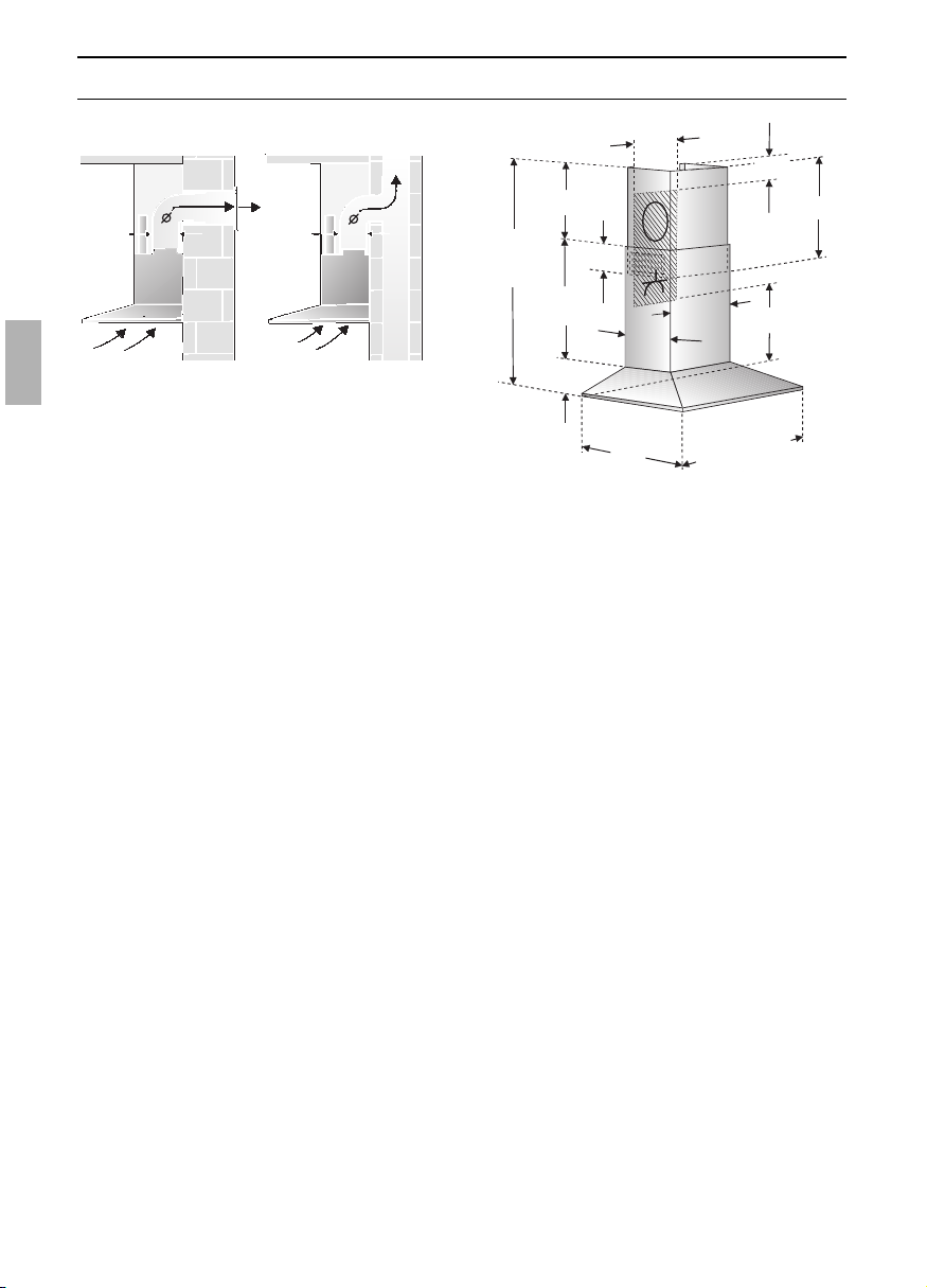
The exhaust air is discharged upwards
through a ventilation shaft or directly
through the outside wall into the open.
D
Exhaust air should neither be directed
into a smoke or exhaust flue that is
currently used for other purposes, nor into
a shaft that is used for ventilating rooms in
which stoves or fireplaces are also located.
Exhaust air may be discharged in
accordance with official and statutory
regulations only (e.g. national building
regulations).
Local authority regulations must be
observed when discharging air into smoke
or exhaust flues that are not otherwise in
use.
D
When the extractor hood is operated
in exhaust-air mode simultaneously with
a different burner which also makes use
of the same chimney (such as gas, oil or
coal-fired heaters, continuous-flow heaters,
hot-water boilers) care must be taken to
ensure that there is an adequate supply
of fresh air which will be needed by the
burner for combustion.
Safe operation is possible provided that the
underpressure in the room where the
burner is installed does not exceed 4 Pa
(0.04 mbar).
This can be achieved if combustion air can
flow through non-lockable openings, e.g. in
doors, windows and via the air-
intake/exhaust-air wall box or by other
technical measures, such as reciprocal
interlocking, etc.
If the air intake is inadequate, there is a
risk of poisoning from combustion gases
which are drawn back into the room.
An air-intake/exhaust-air wall box by itself
is no guarantee that the limiting value will
not be exceeded.
Note: When assessing the overall
requirement, the combined ventilation
system for the entire household must be
taken into consideration. This rule does not
apply to the use of cooking appliances,
such as hobs and ovens.
Unrestricted operation is possible if the
extractor hood is used in recirculating
mode – with activated carbon filter.
If the exhaust air is going to be
discharged into the open, a telescopic
wall box should be fitted into the outside
wall.
Exhaust-air mode
120
150
120
150
mind. 45
700-1105
250
350
580
520
600/
700/
900
90
130
565
mind.550
mind.40
3
1
5

21
Prior to installation
For optimum extractor hood efficiency:
❑
Short, smooth air exhaust pipe.
❑
As few bends in the pipe as possible.
❑
Diameter of pipe to be as large as
possible and no tight bends in pipe.
If long, rough exhaust-air pipes,
many pipe bends or smaller pipe
diameters are used, the air extraction
rate will no longer be at an optimum
level and there will be an increase in
noise.
❑
Round pipes:
We recommend
Internal diameter: 150 mm (at least
120 mm).
❑
Flat ducts must have an internal cross-
section that equates to that of round
pipes.
There should be no sharp bends.
l 120 mm approx. 113 cm
2
l 150 mm approx. 177 cm
2
❑
If pipes have different diameters:
Insert sealing strip.
❑
For exhaust-air mode, ensure that
there is an adequate supply of fresh air.
Circulating-air mode
❑ With activated carbon filter if exhaust-air
mode is not possible.
❑ Attach the exhaust-air pipe to the
reducing connector.
Connecting a l 150 mm exhaust-air
pipe:
❑
Mount the pipe directly onto the air
outlet on the hood.
Connecting a l 120 mm exhaust-air
pipe:
❑ Insert the reducing connector into the air
connector, drill 2x l 3 mm holes and
screw together.
The complete
installation set can
be obtained from
specialist outlets.
The corresponding
accessory numbers
can be found at the
end of these opera-
ting instructions.
775-
1220
mind.
120
250
3
5
0
580
520
6
0
0
/
7
0
0
/
9
0
0
90
565
mind.550
mind.120
315

Prior to installation
Preparing the wall
❑
The wall must be flat and perpendicular.
❑
Ensure that the wall is capable of
providing a firm hold for mounting
screws and plugs.
❑ Appliances with a rear light:
A recess panel or tiles fitted to the wall
directly under the extractor hood must
not project by more than 15 mm,
otherwise the light cover may be
damaged.
Weight in kg:
Exhaust air
Recircula-
ting air
20,260 cm 22,4
21,5 23,770 cm
23,2 25,490 cm
We reserve the right to construction changes within the
context of technical development.
Electrical connection
The extractor hood should only be
connected to an earthed socket that has
been installed according to relevant
regulations.
If possible, site the earthed socket directly
behind the chimney panelling.
Electrical data:
Are to be found on the name plate inside
the appliance after removal of the filter
frame.
Before undertaking any repairs,
always disconnect the extractor hood from
the electricity supply.
Length of the connecting cable: 1.30 m.
If it is necessary to wire the extractor
hood directly into the mains:
The extractor hood should only be
connected to the electricity supply by a
properly qualified electrician.
A separator must be installed in the house-
hold circuit. A suitable separator is a switch
that has a contact gap of more than 3 mm
and interrupts all poles. Such devices
include circuit breakers and contactors.
If the connecting cable for this applian-
ce is damaged, the cable must be replaced
by the manufacturer or his customer
service or a similarly qualified person in
order to prevent serious injury to the user.
This extractor hood corresponds to EC
regulations concerning RF interference
suppression.
Electrical connection
WARNING: THIS APPLIANCE MUST BE
EARTHED
IMPORTANT: Fitting a Different Plug:
The wires in the mains lead are coloured in
accordance with the following code:
Green and Yellow – Earth
Blue – Neutral
Brown – Live
If you fit your own plug, the colours of
these wires may not correspond with the
identifying marks on the plug terminals.
This is what you have to do:
1. Connect the green and yellow (Earth)
wire to the terminal in the plug marked
‘E’ or with the symbol ( ), or
coloured green or green and yellow.
2. Connect the blue (Neutral) wire to the
terminal in the plug marked ‘N’ or
coloured black.
3. Connect the brown (Live) wire to the
terminal marked ‘L’, or coloured red.
22
23
Installation
Note: Take into account any special
accessories that are going to be fitted.
5. Attach the fixing bracket for the
chimney panelling using two hexagon
head cap screws.
6. Screw in the two upper hexagon head
cap screws leaving them extended by
approx. 5 mm.
7. Attach the extractor hood to the
screws.
ca.5mm
This extractor hood is intended to be
mounted onto the kitchen wall.
1. Remove the grease filter (refer to
Operating Instructions).
2. Draw a line on the wall from the ceiling
to the lower edge of the hood at the
centre of the location where the hood is
going to be mounted.
3. Use the template to mark the points on
the wall where the screws will be moun-
ted. In order to make it easier to hook
the hood onto the screws, draw the out-
line of the area where the hood will be
attached.
Ensure that the minimum distance
between the hob and the extractor hood is
maintained – 550 mm for an electric hob
and 650 mm for a gas hob. The bottom
edge of the template equates to the lower
edge of the extractor hood.
4. Drill 4 x l 8 mm holes for the extractor
hood and 2 x l 8 mm holes for the
chimney panelling. Insert plugs into the
holes so that they are flush with the wall.
15
300
230
411
90
1
6
0
mind.550 Elektro
mind.650 Gas
24
Installation
08. Screw in the two lower hexagon head
cap screws.
Before the 4 screws are tightened
down, align the extractor hood properly.
09. Stick protective film over the holes of
the 2 lower mounting bolts in the
protective grid.
13. Push both sections of the flue panelling
together (slots in the upper section
must be pointing downwards) and
insert into the opening in the extractor
hood.
Protect the cover panels from
scratches, for example by laying the
template used for marking the wall over
the top edge of the lower section.
10. Connect up the air outlet pipe.
11. Connect the hood to the electricity
supply.
12. Remove the protective film from the
two flue ducts.
Take care not to damage the
stainless steel surfaces which are
susceptible to scratches etc.
1.
2.
15. Insert the grease filter (refer to
Operating Instructions).
1.
2.
3.
14. Slide out the upper section and attach
it to the mounting brackets at the sides
with two screws.
25
Eclairage
Commuta-
teur Lumière/
Ventilateur
Grille du filtre
Capot de
cheminée
Description de l'appareil
Mode d’emploi:
Modes de fonctionnement
Air évacué à l'extérieur:
❑ Le ventilateur de la hotte aspire les
buées de cuisson qui traversent un filtre
à graisse avant de regagner
l'atmosphère extérieure.
❑ Ce filtre retient les particules grasses
solides en suspension dans les buées de
cuisson.
❑ Les particules grasses ne se déposent
plus dans la cuisine, les odeurs de
cuisson disparaissent.
D
Si la hotte évacue l'air à l'extérieur et
si le logement comporte des moyens de
chauffage (tels par ex. des appareils de
chauffage au gaz, au fuel ou au charbon,
chauffe-eau instantanés ou à accumulation)
raccordés à une cheminée, veiller
impérativement à ce que l'apport d'air
soit suffisant pour assurer la marche du
chauffage à combustion.
Un fonctionnement sans risque est possible
si la dépression dans le local où le foyer de
chauffage est implanté ne dépasse pas 4
Pascals (0,04 mbars).
Modes de fonctionnement
On y parvient en présence d'ouvertures non
obturables ménagées par ex. dans les
portes, fenêtres et en association avec des
ventouses télescopiques d'admission/
évacuation de l'air à travers la maçonnerie
ou par d'autres mesures techniques telles
qu'un verrouillage réciproque ou assimilé
permettant à l'air d'affluer pour assurer la
combustion.
En cas d'afflux d'air insuffisant, risque
d'intoxication par réaspiration des gaz
de combustion.
La présence d'une ventouse télescopique
d'apport et d'évacuation d'air ne suffit pas
à assurer le respect de la valeur limite.
Remarque: lors de l'évaluation de la
situation, toujours tenir compte de
l'ensemble des moyens d'aération du
logement. Cette règle ne vaut généralement
pas si vous utilisez des appareils de cuisson
(table de cuisson et cuisinière à gaz).
Si la hotte recycle l'air aspiré au moyen
d'un filtre au charbon actif, son
fonctionnement ne s'assortit d'aucune
restriction.
Air recyclé:
❑ La hotte doit, dans ce cas, être équipée
d'un filtre au charbon actif (voir le filtre et
son entretien).
Vous pouvez vous procurer le kit de
montage complet ainsi que les filtres de
rechange auprès de votre revendeur
spécialisé.
Vous trouverez les numéros de référence
des accessoires correspondants à la fin
de la présente notice d'utilisation.
❑ Le ventilateur de la hotte aspirante aspire
les buées qui traversent le filtre à graisse
et celui à charbon actif avant de revenir
dans la cuisine.
❑ Le filtre à graisse retient les particules
solides en suspension dans les buées de
cuisson.
❑ Le filtre à charbon actif retient les
substances odoriférantes.
Si vous n'incorporez aucun filtre au
charbon actif, impossible de retenir les
odeurs présentes dans les buées de
cuisson.

26
Dérangements
Si vous avez des questions à poser ou en
cas de dérangement, appelez s.v.p. le
service après-vente.
(Voir la liste des agences du service après-
vente).
Lors de votre appel, veuillez mentionner les
numéros suivants:
N° E FD
Inscrivez les numéros correspondants de
votre hotte dans le cadre ci-dessus. Ces
numéros se trouvent à l'intérieur de
l'appareil, sur la plaque signalétique
accessible une fois la grille de filtre retirée.
Avant la première utilisation
Remarques importantes:
❑ La présente notice d'emploi vaut pour
plusieurs versions de l'appareil.
Elle peut contenir des descriptions
d'accessoires ne figurant pas dans votre
appareil.
❑ Cette hotte aspirante est conforme aux
dispositions de sécurité applicables.
Les réparations ne doivent être
effectuées que par un spécialiste.
Des réparations inexpertes
s'assortissent de risques
considérables pour l'utilisateur.
Lorsque les foyers sont allumés, des
ustensiles de cuisson doivent toujours se
trouver dessus.
L'utilisation d'une hotte aspirante
au-dessus d'un foyer à combustible solide
(charbon, bois, etc.) n'est autorisée qu'à
certaines conditions (voir la notice de
montage).
Tables de cuisson au gaz /
Cuisinières à gaz
Ne faites jamais marcher tous les foyers
au gaz en même temps et à pleine
puissance pendant assez longtemps
(15 minutes max.), sinon vous risquez de
vous brûler en touchant la surface du corps
de la hotte, ou d'endommager carrément
cette dernière. Si la hotte doit marcher
au-dessus d'une table de cuisson au gaz,
faites simultanément marcher la hotte à la
puissance d'aspiration maximale si vous
avez allumé trois foyers ou plus.
❑ Lisez attentivement la présente notice
d'emploi avant d'utiliser votre appareil
pour la première fois. Elle contient des
informations importantes non seulement
pour votre sécurité mais aussi pour
l'utilisation et l'entretien de l'appareil.
❑ Rangez la présente notice de montage
et d'emploi soigneusement pour pouvoir
la remettre à un futur propriétaire de
l'appareil.
Si l'appareil est endommagé, sa mise en
service est proscrite.
Le branchement et la mise en service ne
doivent être effectués que par un spécialiste.
Si le cordon d'alimentation de cet
appareil a été endommagé, il faut confier son
remplacement au fabricant ou à son service
après-vente, ou encore à une personne
possédant des qualifications identiques, pour
éviter de créer des risques.
Eliminez les matériaux d'emballage
conformément à la réglementation (voir la
notice de montage).
Cette hotte aspirante n'est destinée à ser-
vir que pour couvrir les besoins d'un ménage.
Ne faites marcher la hotte aspirante
qu'ampoules montées sur leur douille.
Remplacez immédiatement les
ampoules défectueuses pour empêcher une
surcharge des ampoules restantes.
N'utilisez jamais la hotte aspirante sans
filtre à graisse.
Les graisses ou huiles surchauffées peu-
vent s'enflammer facilement.
Par conséquent, surveillez toujours les plats
(frites par ex.) qui se préparent à l'aide de
matières grasses ou d'huiles.
Ne flambez aucun mets sous la hotte.
Les flammes risqueraient d'atteindre le
! filtre à graisse et d'y mettre le feu.
27
Utilisation de la hotte aspirante
Filtre et entretien
Filtres à graisse:
Vous pouvez utiliser divers filtres pour
retenir les particules grasses en
suspension dans les buées de cuisson.
Ces nattes filtrantes sont en métal
incombustible.
Attention:
Plus elles se saturent en particules grasses
et plus elles risquent de s'enflammer.
D'autre part, leur saturation risque de gêner
le bon fonctionnement de la hotte.
Important:
Prévenez tout risque d'incendie en
nettoyant à temps les filtres à graisse en
métal. Ce risque est dû à l'accumulation de
chaleur pendant la friture ou le rôtissage.
Nettoyage des filtres à graisse en métal:
❑ En fonctionnement normal (1 à 2 heures
par jour), le filtre doit être nettoyé au bout
de 8 à 10 semaines.
❑ Ces filtres sont nettoyables au lave-
vaisselle. Ils peuvent changer légèrement
de couleur au lavage.
❑ Le filtre doit reposer non serré dans le
lave-vaisselle.
Il ne doit pas être coincé.
Important:
Ne lavez pas en même temps la vaisselle
et les filtres métalliques fortement
saturés en matière grasse.
❑ Si vous les nettoyez à la main, mettez les
filtres à tremper pendant plusieurs heures
dans de l'eau très chaude additionnée de
produit à vaisselle.
Ensuite, brossez les filtres, rincez-les bien
puis laissez-les goutter.
La méthode la plus efficace pour
supprimer les buées de cuisson consiste à:
❑
Enclencher la hotte aspirante
en début de cuisson.
❑
Eteindre la hotte aspirante
quelques seulement minutes après la fin
de la cuisson.
1
23
1
23
Eclairage
Arrêt/Marche
Puissances
d'aspiration
Enclenchement:
❑
Amenez le commutateur à curseur sur la
puissance d'aspiration désirée.
Coupure:
❑
Ramenez le commutateur à curseur sur
0.
Aspiration intensive:
Cette position permet au ventilateur de
développer sa puissance d'aspiration maxi.
Vous n'en aurez besoin que brièvement.
❑
Poussez le commutateur à curseur à
fond à droite.
Pendant que la hotte fonctionne sur la
puissance d'aspiration intensive, la barre
s'allume sur le commutateur à curseur.
Eclairage:
❑
Vous pouvez utiliser l'éclairage à tout
moment, même quand le ventilateur est
éteint.
Aspiration intensive
28
Retrait et mise en place des filtres à
graisse en métal:
1. Poussez dans le sens de la flèche le
cran situé contre chaque filtre à graisse
puis abaissez les filtres.
Mise en place du filtre:
1. Retirez d'abord les filtres à graisse (voir
la section intitulée "Retrait et mise en
place des filtres à graisse en métal).
2. Mettez en place le filtre à charbon actif.
Filtre et entretien
3. Faites encranter les pattes des deux
côtés.
4. Remontez les filtres à graisse en métal
(voir la section intitulée "Retrait et mise
en place des filtres à graisse en métal).
Retrait du filtre:
1. Retirez les filtres à graisse en métal.
2. Appuyez sur les pattes situées des deux
côtés puis retirez le filtre à charbon actif
par le bas.
2. Nettoyer les filtres à graisse.
3. Une fois nettoyés, remettez les filtres à
graisse en place.
Filtre à charbon actif:
Ce filtre sert à retenir les substances
odoriférantes lorsque la hotte recycle l'air.
Attention:
Plus elles se saturent en particules grasses
et plus elles risquent de s'enflammer.
D'autre part, leur saturation risque de gêner
le bon fonctionnement de la hotte.
Important:
Un changement à temps des filtres à
charbon actif prévient le risque d'incendie.
Ce risque est dû à l'accumulation de
chaleur qui se produit pendant une friture
ou la cuisson d'un rôti.
3. Remontez les filtres à graisse.
Changement du filtre à charbon actif:
❑ Hotte fonctionnant normalement
(1 à 2 heures par jour), il faudra changer
les filtres à charbon actif environ 1 fois
par an.
❑ Vous pouvez vous procurer un filtre à
charbon actif de rechange dans le
commerce spécialisé. Voir la section sur
les accessoires spéciaux.
❑ N'utilisez qu'un filtre d'origine.
Vous garantirez ainsi un fonctionnement
optimal de la hotte.
Mise au rebut du filtre à charbon actif
usagé:
❑ Les filtres à charbon actif ne contiennent
aucune substance nocive. Vous pouvez
les mettre à la poubelles de déchets
résiduels.
29
Nettoyage et entretien
Avant tout nettoyage et entretien, mettez
d'abord la hotte hors tension en débran-
chant la fiche mâle de la prise de courant
ou en coupant le disjoncteur/fusible.
❑ Lors du nettoyage des filtres à graisse,
nettoyez la graisse qui s'est déposée
dans les endroits accessibles du corps de
hotte. Vous prévenez ainsi les risques
d'incendie et garantissez ainsi un
fonctionnement optimal de la hotte.
❑ Pour la nettoyer, utilisez de l'eau chaude
additionnée de produit à vaisselle ou un
liquide non agressif à laver les fenêtres.
❑ Ne tentez pas de gratter les salissures.
Ramollissez-les avec un essuie-tout
humide.
❑ N'utilisez pas de produits récurants ni
d'éponges à dos abrasif.
❑ Remarque: ne nettoyez pas les surfaces
en plastique avec de l'alcool (à brûler) car
des taches mates pourraient
apparaître.
Prudence: ventilez suffisamment la
cuisine, n'utilisez jamais de flamme nue.
Veuillez ne nettoyer le commutateur à
curseur qu'au moyen d'un chiffon doux et
humide (contenant un peu d'eau additionnée
de produit à vaisselle). Pour nettoyer le
commutateur à curseur, n'utilisez pas de
détergent pour les surfaces en acier.
Surfaces en acier inox:
❑ Veuillez utiliser un produit pour l'acier inox
qui le nettoie sans le rayer.
❑ Frottez toujours l'acier inox dans le sens
de son polissage.
Ne nettoyez jamais les surfaces en acier
inox avec des éponges à dos
récurant, et pas non plus avec des
détergents à base de sable, soude
caustique, acide ou chlore.
Surfaces en aluminium et en plastique:
❑ Utilisez un chiffon doux, ne peluchant pas,
du genre employé pour nettoyer les vitres,
ou un chiffon à microfibres.
❑ N'utilisez pas de chiffons secs.
❑ Utilisez un produit pour vitres mais non
aggressif.
❑ N'utilisez pas de détergents aggressifs,
contenant un acide ou une base.
❑ N'utilisez pas de produits récurants.
Changement du tube au néon
4. Remettez le cache de l'éclairage en
place.
5. Pour remettre la hotte sous tension,
rebranchez la fiche mâle dans la prise de
courant ou remontez le fusible/réarmez
le disjoncteur.
1. Avant tout nettoyage et entretien, mettez
d'abord la hotte hors tension en débran-
chant la fiche mâle de la prise de cou-
rant ou en coupant le disjoncteur/fusible.
2. Enfoncez légèrement les deux pattes du
cache de l'éclairage puis retirez le cache
par le bas.
3. Remplacez le tube au néon (tube en
vente habituelle dans le commerce,
puissance 11 watts maxi., douille G23).
Attention: le tube est enfoncé dans la
douille.

30
Remarques importantes
Notice de montage:
Remarques supplémentaires
concernant les cuisinières à gaz:
Lors du montage de foyers gaz, veuillez
respecter les dispositions légales en
vigueur dans votre pays (En Allemagne par
ex: les Règles technique TRGI régissant
l'installation du gaz).
Respectez les prescriptions et
consignes d'encastrement en leur version
applicable publiées par les fabricants
d'appareils au gaz.
La hotte aspirante ne pourra cotoyer
que sur un côté un meuble haut ou une
paroi haute. Ecart minimum: 50 mm.
Ecart minimum, en présence de
foyers au gaz, entre le bord supérieur
de la grille support et le bord inférieur de la
hotte: 650 mm, fig. 1.
Les anciens appareils ne sont pas des
déchets sans valeur.
Leur élimination respectueuse de
l'environnement permet de récupérer de
précieuses matières premières.
Avant de vous débarrasser de l'appareil,
rendez-le inutilisable.
Pour vous parvenir en parfait état, votre
nouvel appareil a été conditionné dans un
emballage qui le protège efficacement.
Tous les matériaux d'emballage utilisés
sont compatibles avec l'environnement et
recyclables. Aidez-nous à éliminer
l'emballage en respectant l'environnement.
Demandez à votre revendeur ou à votre
mairie quelles sont les formes de recyclage
actuellement possibles.
Cette hotte peut évacuer l'air à
l'extérieur ou le recycler.
Fixez toujours la hotte bien centrée
au-dessus des foyers de la table de
cuisson.
L'écart minimum entre les foyers
électriques et le bord inférieur de la hotte
doit être de 550 mm, voir fig. 1.
Au-dessus d'un foyer à combustible
solide générateur d'un risque d'incendie (par
projection d'étincelles par ex.), le
montage de la hotte ne sera admis que si ce
foyer est équipé d'un couvercle fermé et
inamovible et si le montage ne
contrevient pas à la réglementation
nationale. Cette restriction ne vaut pas pour
les cuisinières à gaz et les foyers aux gaz.
Plus l'écart est faible entre la hotte
aspirante et les foyers et plus il se pourra
que la vapeur montant des casseroles se
condense et forme des gouttes sur la face
inférieure de la hotte.
 Loading...