


 Loading...
Bosch ventilation installation manual DKE96

Table of Contents |
|
Safety ...................................................................................................................... |
1 |
Installation ............................................................................................................... |
2 |
Before You Begin .................................................................................................................... |
2 |
Installation Procedure.............................................................................................................. |
4 |
Service .................................................................................................................... |
7 |
Before Calling Service............................................................................................................. |
7 |
Product Data Plate............................................................................................................. |
7 |
Questions?
1-800-944-2904
www.boschappliances.com
5551 McFadden Ave.
Huntington Beach, CA 92649
We look forward to hearing from you!

Safety
IMPORTANT SAFETY INSTRUCTIONS
READ AND SAVE THESE INSTRUCTIONS
INSTALLER: LEAVE THESE INSTRUCTIONS WITH THE APPLIANCE AFTER INSTALLATION IS COMPLETE. IMPORTANT: SAVE FOR THE LOCAL INSPECTOR'S USE.
Important Safety
Instructions
WARNING: Improper installation, adjustment, alteration, service or maintenance can cause injury or property damage. Refer to this manual. For assistance or additional information consult a qualified installer, service agency, or manufacturer.
•Have the installer show you the location of the circuit breaker or fuse. Mark it for easy reference.
•Be sure your appliance is properly installed and grounded by a qualified technician.
Equipment and Usage Safety Requirements
•Before you plug in an electrical cord, be sure all controls are in the OFF position.
•WARNING: TO REDUCE THE RISK OF FIRE, ELECTRIC SHOCK, OR INJURY TO PERSONS, OBSERVE THE FOLLOWING:
•Use this unit only in the manner intended by the manufacturer. If you have questions, contact the manufacturer.
•Before servicing or cleaning the unit, switch power off at service panel and lock service panel. This will prevent power from being switched on accidentally. When the service panel cannot be locked, securely fasten a prominent warning device, such as a tag, to the service panel.
•Installation work and electrical wiring must be done by qualified person(s) in accordance with all applicable codes & standards, including fire-rated construction.
•Sufficient make-up air is needed for proper combustion and exhausting of gases through the flue (chimney) of fuel burning equipment to prevent backdrafting. Follow the heating equipment manufacturer’s guideline and safety standards such as those published by the National Fire Protection Association (NFPA), the American Society for Heating, Refrigeration and Air Conditioning Engineers (ASHRAE), and the local code authorities.
•Due to the size and weight of this unit, two installers are recommended.
•When cutting or drilling into wall or ceiling, do not damage electrical wiring or other hidden utilities.
•To properly exhaust air, be sure to duct air outside. Do not vent exhaust air into spaces within walls, ceilings, attics, crawl spaces, or garages.
•Install this hood in accordance with all requirements specified.
•The hood is equipped with an internal blower. Other ventilator blowers CANNOT be substituted.
•WARNING - TO REDUCE THE RISK OF FIRE, USE ONLY METAL DUCTWORK.
•WARNING: Turn off power circuit at service panel and lock out panel before wiring this appliance.
English 1

•CAUTION: This unit is approved for use with residential appliances. For general residential kitchen ventilating use only. DO NOT use to exhaust hazardous or explosive materials or vapors. Vent unit to the outside.
•To reduce the risk of fire or electric shock, do not use the fan with any solidstate speed control device.
•This appliance has been found to be in compliance with UL507 Standard for Electric Fans and CAN/CSA-22.2 No. 113 Canadian Standard for Fans and Ventilators. It is the responsibility of the owner and the installer to determine if additional requirements or standards apply in specific installations.
Installation
Before You Begin
Tools and Parts
Needed
1.Metal Duct Cover (optional)
2.Ductwork as necessary (style varies)
3.Duct Tape
4.Phillips Head Screwdriver
5.Drill with 1/4” bit (6 mm)
6.Tape Measure
7.Screwdriver
Parts Included
1.Chimney sections (2)
2.Filter
3.Hood
4.Transition
5.One Way Damper
6.Screws, 5x60 (6)
7.Sheet Metal Screws, 3.9 (2)
8.UX6 plugs (6)
9.Positioning Templates (2)
General Information
If parts are missing or damaged, call the number or write to the address listed inside the front cover.
The hood is equipped with an internal blower. It is not designed for use with a remote blower.
Hood installation height above cooktop is the user’s preference. The lower the hood above the cooktop, the more efficient the capturing of cooking odors, grease, and smoke. This hood has been approved for installations as low as 30” (760 mm) and as high as 36” (900 mm) above the cooktop. The lower height may be inconvenient for tall people and large cooking vessels.
In addition, the chimney sections, when fully extended, measure 42 3/4” (1090 mm) tall. In order for the upper chimney section to meet the ceiling (or surface above), the highest allowable ceiling height is 9 1/2’ (3 m)(assumes the hood is installed 36” (900 mm) above the cooktop).
English 2
Ducting Recommendations
Overall Dimensions
The hood can be ducted to the outside or used with a recirculation unit. The recirculation unit is available from your dealer.
For the most efficient air flow exhaust, use a straight duct run or as few elbows as possible.
Do not use flex ducting. Always use metal ductwork with minimum diameter of 6” (150 mm). A transition is necessary to connect to larger diameter ductwork or to square ductwork.
COLD WEATHER installations should have an additional backdraft damper installed to minimize backward cold air flow and a nonmetallic thermal break to minimize conduction of outside temperatures as part of the ductwork. The damper should be on the cold air side of the thermal break. The break should be as close as possible to where the ducting enters the heated portion of the house.
Always install a metal vent cover where the ductwork exits the house.
Make-Up Air: Local building codes may require the use of make-up air systems when using ducted ventilation systems greater than specified CFM of air movement. The specified CFM varies from locale to locale. Consult your HVAC professional for specific requirements in your area.
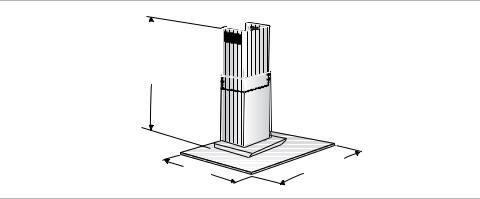
The overall dimensions are:
•Width: 35 1/2" (900 mm); 30” (760 mm)
•Depth: 20 1/2" (520 mm)
•Height: 28-43” (715-1100 mm), depending on chimney extension
28-43" |
|
|
|
|
(715-1100 mm) |
|
|
|
|
|
|
|
1/2" |
|
|
|
35 |
mm) |
|
20 |
1/2" |
/ |
|
|
30" |
/900 |
|||
(520 |
mm |
|
||
mm) |
|
|||
(760 |
|
|
||
|
|
|
||
Figure 1: Overall Dimensions
Mounting Requirements The hood must be mounted through the back wall. It cannot be mounted from above. See “General Information” on page 2 for suggestions for determining hood height.
For safety purposes, the wall must be able to support three times the weight of the hood. See “Minimum Weight Requirements” on page 3 for the minimum amount of weight the wall must support. Note: At least one screw must be installed through a stud.
Table 1: Minimum Weight Requirements
Size |
With Recirculation Kit |
Without Recirculation Kit |
|
|
|
30” (760 mm) |
189 lbs. (85.5 kg) |
152 lbs. (69 kg) |
|
|
|
36” (900 mm) |
202 lbs. (91.5 kg) |
167 lbs. (75.5 kg) |
|
|
|
English 3
Power Requirements Electrical Specifications: 120V AC, 60Hz. 15A Branch Circuit
Installation Procedure
|
|
WARNING: To avoid electrical shock hazard, before installing, |
|||
|
|
switch power off at the service panel and lock the panel to prevent the |
|||
|
|
power from being switched on accidentally. |
|||
1) |
Unpack Hood |
Pull hood from outer packaging. Remove and discard all packaging materials. |
|||
|
|
Remove filter and set aside (See Use and Care manual for removal instructions). |
|||
2) |
Prepare ductwork |
Install one-way damper so that the flap opens up. Press damper down into the |
|||
|
|
blower outlet until it is snug. Note: verify that the flap opens up (toward the ceiling) |
|||
|
|
before continuing. See “Prepare Ductwork” on page 4. If necessary, install transi- |
|||
|
|
tion, thermal break and additional backdraft damper. |
|||
|
|
|
|
|
|
|
|
|
|
|
|
|
|
|
|
|
|
|
Figure 2: Prepare Ductwork |
3) Prepare Wall |
See “General Information” on page 2 for recommended installation height and |
|
“Mounting Requirements” on page 3 for information on wall requirements. |
|
Once the preferred height is determined, draw a line at the vertical centerline of |
|
the cooking appliance. |
|
Use the installation template to locate and mark the screw holes. Drill 1/4” (6 mm) |
|
pilot holes (4 holes for hood screws and 2 holes for chimney screws). Install plugs |
English 4

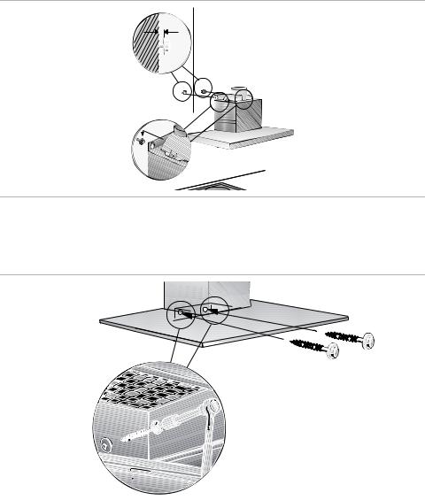
4)Attach Chimney Mounting Bracket
in screw holes so that they are flush with the wall.Note: At least one screw must be installed through a stud. Leave a 3/8” (6 mm) of each screw exposed.
chimney screw holes
centerline
template
upper hood screw holes
lower hood screw holes |
30" min. |
|
Figure 3: Prepare Wall
Attach spacers to holes on chimney mounting bracket arms, as seen in “Attach Mounting Brackets” on page 5.
Attach chimney mounting bracket to wall through chimney screw holes created in previous step. Use two screws.
|
|
|
|
|
|
|
|
|
|
|
Figure 4: Attach Mounting Brackets |
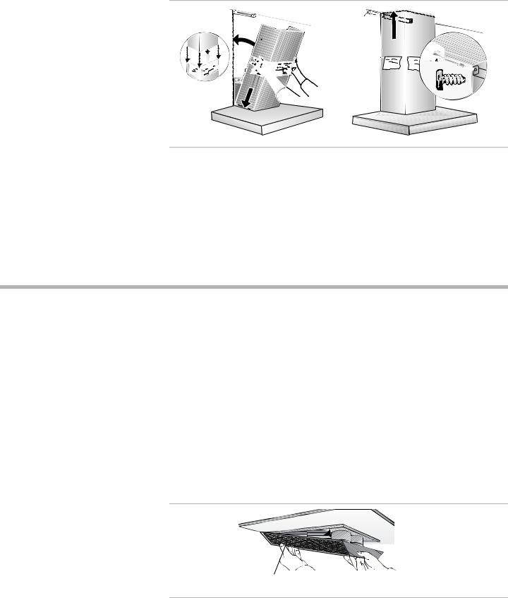
5) Hang the Hood |
Place the hood by sliding the mounting holes in the top of the hood over the top |
||
|
hood screws. Check and adjust for level. Tighten the screws. |
||
English 5
Note: Be sure that the glass screen is not touching the back wall.
1/4"
Figure 5: Hang the Hood
Install two lower hood screws from underneath.
|
|
|
|
|
|
|
|
|
|
|
|
|
|
|
|
|
|
|
|
|
|
|
|
|
|
|
|
|
|
|
|
|
|
|
|
|
|
|
|
|
|
|
|
|
|
|
|
|
|
|
|
|
|
|
|
|
|
|
|
|
|
|
|
|
|
|
|
|
|
|
|
|
|
|
|
|
|
|
|
|
|
|
|
|
|
|
|
|
|
|
|
|
|
|
|
|
|
|
|
|
|
|
|
|
|
|
|
|
|
|
|
|
|
|
|
|
|
|
|
|
|
|
|
|
|
|
|
|
|
|
|
|
|
|
|
|
|
|
|
|
|
|
|
|
|
|
|
|
|
|
|
|
|
|
|
|
|
|
|
|
|
|
|
|
|
|
|
|
|
|
|
|
|
|
|
|
|
|
|
|
|
|
|
|
|
|
|
|
|
|
|
|
|
|
|
|
|
|
|
|
|
|
|
|
|
|
|
|
|
|
|
|
|
|
|
|
|
|
|
|
|
|
|
|
|
|
|
|
|
|
|
|
|
|
|
|
|
|
|
|
|
|
|
|
|
|
|
|
|
|
|
|
|
|
|
|
|
|
|
|
|
|
|
|
|
|
|
|
|
|
|
|
|
|
|
|
|
|
|
|
|
|
|
|
|
|
|
|
|
|
|
|
|
|
|
|
|
|
|
|
|
|
|
|
|
|
|
|
|
|
|
|
|
|
|
|
|
|
|
|
|
|
|
|
|
|
|
|
|
|
|
|
|
|
|
|
|
|
|
|
|
|
|
|
|
|
|
|
|
|
|
|
|
|
|
|
|
|
|
|
|
|
|
|
|
|
|
|
|
|
|
|
|
|
|
|
|
|
|
|
Figure 6: Install Lower Hood Screws |
||||||||||
6) |
Connect to Ductwork |
Connect hood to ductwork in house. |
|||||||||||||||||||||||||
7) |
Connect Electric |
Plug electrical cord into grounded outlet. Note: The hood requires a 120V AC, |
|||||||||||||||||||||||||
|
|
60Hz., 15A Branch Circuit. |
|||||||||||||||||||||||||
8) |
Install Chimney |
Remove protective film from both sections of chimney. |
|||||||||||||||||||||||||
|
|
Connect the sections, one inside the other. For recirculation, the slots in the upper |
|||||||||||||||||||||||||
|
|
chimney section should be at the end closest to the ceiling. When venting to the |
|||||||||||||||||||||||||
|
|
outside, the top section can be turned upside down to conceal the vents. |
|||||||||||||||||||||||||
CAUTION: Be careful not to scratch chimney surface when connecting. Slide templates between the two chimney sections to protect them.
English 6
Insert bottom edge of chimney into top of hood. Slide upper section up until it is flush with the surface above. Attach to chimney mounting bracket with two sheet
metal screws. |
|
1. |
3. |
2. |
|
|
Figure 7: Install Chimney |
9) Final Steps |
Remove templates from between chimney sections if necessary. Remove protec- |
|
tive film from hood. Install grease filters (See Use and Care Manual). |
|
Test the installation. |
|
Note: Be sure to check for backdraft. With the blower on high, close the windows |
|
and doors to the area to ensure that fan does not cause back drafting in any outlet |
|
vent for another appliance. |
Service
Before Calling
Service
Product Data Plate
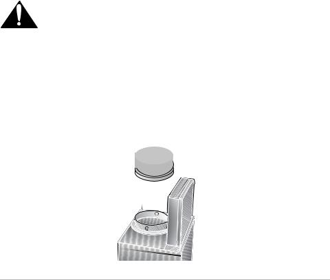
See Use and Care Manual for troubleshooting information. Refer to the Warranty in the Use and Care Manual. Please be prepared with the information printed on your product data plate when calling.
The data plate shows the model and serial number. It is located under the filter.
Keep your invoice or escrow papers for warranty validation if service is needed.
Filter Data Plate
Figure 8: Data Plate Location
English 7
Loading...