


 Loading...
DS7465i
Installation Instructions
EN Input/Output Module
DS7465i | Installation Instructions | 1.0 |
Introduction |
EN | 2 |
|
|
|
1.0 Introduction
The DS7465i Input/Output Module operates with compatible multiplex systems. It has a Form “C” relay (the output zone) that is programmed to activate from several different system events. The DS7465i can also monitor normally open (NO) or normally closed (NC) contacts and report their status as a multiplex address to the control system. Up to 60 DS7465i Modules can be used on the DS7400Xi. Use up to 20 DS7465i Modules per bus on compatible fire alarm control panels (FACPs). When installing the DS7465i with a D8125MUX, refer to the D8125MUX Operation and Installation Guide (P/N: F01U034973) and the D9412GV2/D7412GV2 Approved Applications Compliance Guide (P/N: F01U003639).
2.0 Installation
These installation instructions assume the control panel is installed and in proper working condition.
Perform the following procedure to install the DS7465i:
You must program the control panel and set the DS7465i address switches before the DS7465i can operate.
1.Program the DS7465i and the control panel as described in the control panel’s reference guide.
Disconnect power to the control panel before running wires and connecting the DS7465i.
2.To remove the cover of the DS7465i, place your thumb directly above the lip of the DS7465i and press in and up. Refer to Figure 1.
Figure 1: Removing the Cover
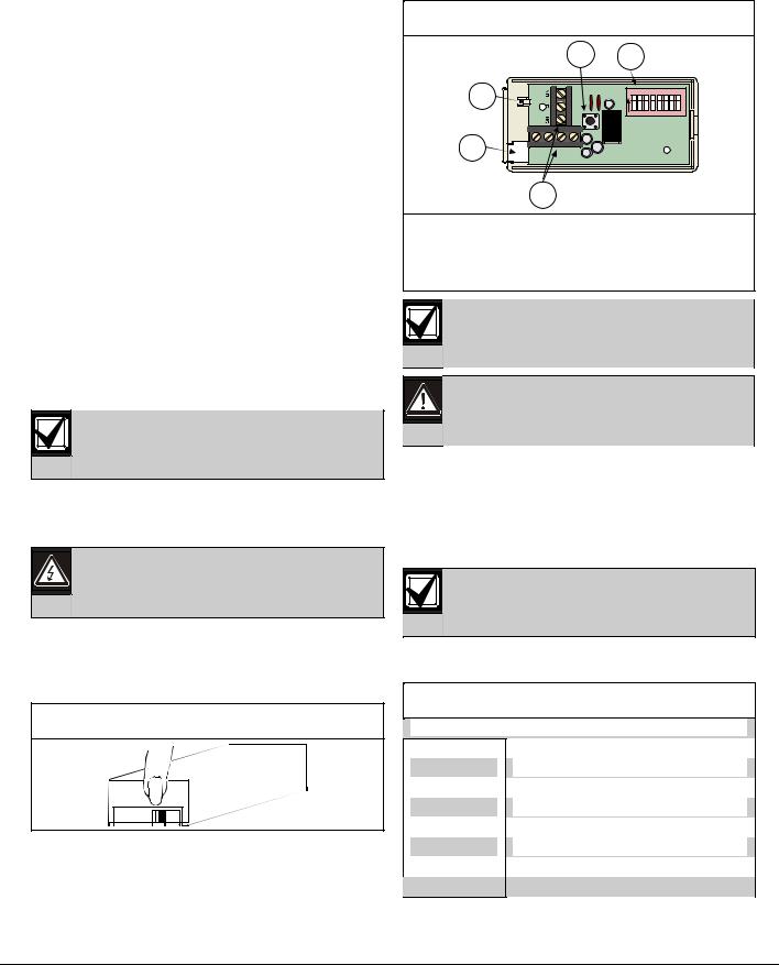
3.To remove the DS7465i circuit board from the base, press the circuit board retainer tab and pull the circuit board up and out of the base.
Refer to Figure 2.
Figure 2: Removing the Circuit Board
2 3
1 |
NO 1 2 3 4 5 6 7 8 |
|
5 |
G |
1 |
- |
+ |
4
1 |
- |
Circuit board |
4 - |
Terminal strips |
|
|
retainer tab |
5 - |
Wire entrance |
2 |
- Tamper switch |
|
|
|
3 |
- |
Address switches |
|
|
When used in a fire system, NFPA 72 prohibits this product from sharing a communications bus with non-fire devices.
Hold the circuit board by its edges to avoid damaging it.
4.Insert the wiring through the wire entrance of the base.
5.Mount the base using the supplied screws. Surface-mount the DS7465i near the devices it controls or monitors.
6.Return the DS7465i circuit board to the base.
After any programming or hardware change, do a functional test of the system as required by local codes.
3.0 Wiring
Table 1: DS7465i Terminal Descriptions
|
|
|
|
|
Terminal |
Description |
|
|
|
|
|
|
NO |
|
Normally open relay contact |
|
C |
Common relay contact |
|
|
|
|
|
|
NC |
|
Normally closed relay contact |
|
G |
Input zone ground |
|
|
|
|
|
|
1 |
|
Input |
|
|
|
|
-Multiplex bus negative
+Multiplex bus positive
Bosch Security Systems, Inc. | 10/09 | F01U070743-03

DS7465i | Installation Instructions | 3.0 |
Wiring |
EN | 3 |
|
|
|
The input zone is power limited and supervised. The output relay must only be used on power-limited circuits.
Fire applications require NO contacts on the input zone.
Connect wiring to the DS7465i as shown in Figure 3 through Figure 5.
The input loop is designed to monitor NO or NC dry contacts. It is supervised using a 47 kΩ end-of-line (EOL) resistor. If using the input loop as a fire alarm input, order the Multiplex Resistor Kit (P/N: 28010).
Do not loop wire around the terminals.
The relay contacts are rated 1A @ 30 VDC for resistive loads. Do not use with inductive or capacitive loads.
Figure 3: DS7430 Multiplex Expansion Module |
|||
|
Wiring |
|
|
|
DS7465i |
DS7430 |
|
|
|
||
|
5 |
1 |
2 |
|
3 |
|
|
|
4 |
|
|
1 |
- Power |
|
|
2 |
- Bus |
|
|
3 |
- To DS7430 Mux Bus Terminals |
|
|
4 |
- EOL 47 kΩ (P/N 26069) |
|
|
5 |
- Form “C” dry contacts rated at 1A @ 30 VDC |
||
For UL Listed fire installations, use NO contacts and order the Multiplex Resistor Kit (P/N: 28010).
Figure 4: DS7436 Multiplex Expansion Module
Wiring
DS7465i |
|
|
|
|
|
6 |
|
DS7436 |
|
||
1 |
2 |
1 |
2 |
||
|
|||||
4 |
3 |
|
5 
1 - Power
2 - Bus
3 - Use either Bus A or Bus B, or both. Refer to the control panel’s reference guide.
4 - To DS7436 B+/B- terminals
5 - EOL 47 kΩ (P/N 26069)
6 - Programmable Form “C” dry contacts rated at
1A @ 30 VDC
For UL Listed fire installations, use NO contacts and order the Multiplex Resistor Kit (P/N: 28010).
Figure 5: D8125MUX Multiplex Expansion
Module Wiring
DS7465i |
|
|
1 |
|
|
9 |
|
|
|
||
2 |
3 |
4 |
5 |
||
|
|||||
|
+ - |
+ - |
+ - |
+ - |
|
|
7 |
|
|
6 |
|
|
|
|
|
8
1 - D8125 Multiplex Module
2 - Power A
3 - MUX Bus A
4 - Power B
5 - MUX Bus B
6 - Use either Bus A or Bus B. Refer to the control panel’s reference guide
7 - To MUX Expansion Module MUX Bus +/- terminals 8 - EOL 47 kΩ (P/N 26069)
9 - Form “C” dry contacts rated at 1A @ 30 VDC
Bosch Security Systems, Inc. | 10/09 | F01U070743-03
Loading...