


ARD-AYH12
Table of contents
 Loading...
ARD-AYH12
de Installationshandbuch
en Installation manual
es Manual de instalación
fr Manuel d'installation
hu Telepítési kézikönyv
nl Installatiehandleiding
pl Instrukcja instalacji
pt Manual de instalação
ru Руководство по установке
zh 安装手册


| 3
de Installationshandbuch 5
en Installation manual 13
es Manual de instalación 21
fr Manuel d'installation 29
hu Telepítési kézikönyv 37
nl Installatiehandleiding 45
pl Instrukcja instalacji 53
pt Manual de instalação 61
ru Руководство по установке 69
zh 安装手册 77
| |

4 |
| |

ARD-AYH12 Inhaltsverzeichnis | de 5
Inhaltsverzeichnis
1 Installationshandbuch 6
1.1 MONTAGEANLEITUNG 6
1.2 VERKABELUNGSANLEITUNG 7
1.3 BEDIENUNGSANLEITUNG 9
1.4 TECHNISCHE DATEN 10
1.5 MONTAGEDARSTELLUNG 10
2 Technischer Kundendienst 12
Bosch Access Systems GmbH Installationshandbuch | V 1.4 | 2010.04
6 de | Installationshandbuch ARD-AYH12
1 Installationshandbuch
Der ARD-AYH12 ist ein RFID-Leser für berührungslose Ausweise
und kann in Zutrittskontrollsysteme installiert werden.
Dieses Installationshandbuch enthält folgende Informationen:
–Montageanleitung
– Verkabelungsanleitung
– Bedienungsanleitung
– Technische Daten
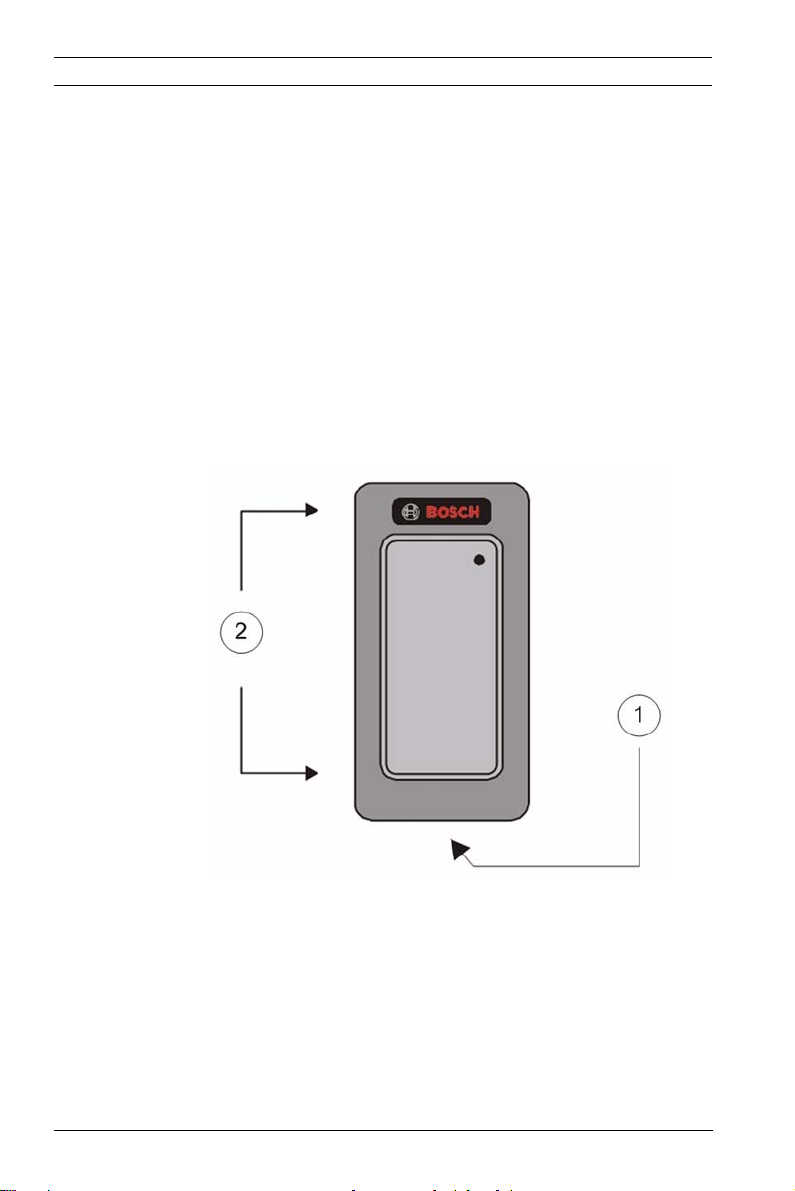
1.1 MONTAGEANLEITUNG
1 = Um die obere Abdeckung zu entfernen, muss die an der
Unterseite des Lesers befindliche Schraube der oberen
Abdeckung abgeschraubt werden.
2 = Entfernen Sie die obere Abdeckung, um die
Schraubenöffnungen für die Montage freizulegen.
| V 1.4 | 2010.04 Installationshandbuch Bosch Access Systems GmbH
ARD-AYH12 Installationshandbuch | de 7
Montieren Sie den Leser wie auf der Schablone angegeben mit
den entsprechenden Schrauben (nicht im Lieferumfang
enthalten).
Gehen Sie zur Montage des Lesers wie folgt vor:
1. Legen Sie eine geeignete Montageposition für den Leser fest.
2. Ziehen Sie die Rückseite der mit dem Gerät mitgelieferten
selbstklebenden Montagemarkierungsschablone ab, und
bringen Sie die Schablone an der gewünschten
Montageposition an. Wenn Sie über keine selbstklebende
Montagemarkierungsschablone verfügen, können Sie die
Abmessungen aus den Montagedarstellungen in diesem
Handbuch entnehmen.
3. Bohren Sie die Löcher (der Bohrungsdurchmesser ist auf
der Montageschablone angegeben) für die Montage des
Lesers auf der entsprechenden Oberfläche.
4. Bohren Sie ein Loch mit
10 mm Durchmesser für das Kabel.
Bei der Montage auf Metall ist die Bohrungskante mit einer
Schutzmanschette oder mit Isolierband zu versehen .
5. Führen Sie das Schnittstellenkabel vom Leser zum Kontroller. Es wird empfohlen, ein Netzteil mit linearer Spannungsregelung zu verwenden.
HINWEIS!
Kartenleser müssen zusammen mit einem zugelassenen
Zutrittskontrollgerät verwendet werden, dessen Netzteil CEzugelassen ist bzw. das mit einem gleichwertigen Netzteil
ausgestattet ist.
1.2 VERKABELUNGSANLEITUNG
Der ARD-AYH12 wird mit einem 45 cm langen 6-adrigen
Anschlusskabel geliefert.
Gehen Sie zum Anschließen des Lesers an den Kontroller wie
folgt vor:
Bosch Access Systems GmbH Installationshandbuch | V 1.4 | 2010.04

8 de | Installationshandbuch ARD-AYH12
1. Bereiten Sie das Leser-Kabel vor, indem Sie den
Kabelmantel auf einer Länge von
Drähte auf einer Länge von
3,4 cm entfernen und die
1,3 cm abisolieren.
2. Bereiten Sie das Kontroller-Kabel vor, indem Sie den
Kabelmantel auf einer Länge von
Drähte auf einer Länge von
3,4 cm entfernen und die
1,3 cm abisolieren.
3. Verbinden Sie die Drähte der Anschlussleitung des Lesers mit den entsprechenden Drähten des Controller-Kabels, und isolieren Sie alle Verbindungsstellen mit Isolierband.
4. Wenn der Sabotageausgang verwendet wird, schließen Sie den violetten Draht an den entsprechenden Eingang am Controller an.
5. Schneiden Sie alle nicht verwendeten Leiter zurück, und isolieren Sie sie entsprechend.
In der nachfolgenden Tabelle ist die Verdrahtung des Lesers mit dem Kontroller angegeben.
Farbe Wiegand-Ausgang
Rot DC+-Eingang Schwarz Masse Weiß Daten 1 Grün Daten 0 Braun LED-Steuerung Violett Sabotage
Hinweise zur Verkabelung:
1. Die einzelnen Adern des Lesers sind nach dem empfohlenen Wiegand-Standard farbcodiert.
2. Bei Verwendung eines separaten Netzteils für den Leser muss für dieses Netzteil und das Netzteil des Kontrollers eine gemeinsame Masse vorhanden sein.
3. Die Abschirmung ist an einen Erdanschluss (optimale
Lösung) bzw. Erdleiter am Panel oder auf der Netzteilseite
des Kabels anzuschließen. Diese Konfiguration ist für die
| V 1.4 | 2010.04 Installationshandbuch Bosch Access Systems GmbH

ARD-AYH12 Installationshandbuch | de 9
Abschirmung des Leser-Kabels gegen externe Störungen
die beste Lösung.
1.3 BEDIENUNGSANLEITUNG
Nach der Verkabelung mit einem Netzteil und dem Kontroller ist
die Funktion des Lesers zu überprüfen.
Gehen Sie dabei wie folgt vor:
1. Schalten Sie den Leser ein. Die LED und der akustische Signalgeber werden dreimal aktiviert. Damit wird signalisiert, dass der Leser ordnungsgemäß funktioniert.
2. Lesen Sie den entsprechenden berührungslosen Ausweistyp mit dem Leser ein. Die LED blinkt kurz grün, und es ertönt ein kurzes akustisches Signal. Damit wird angezeigt, dass die Karte ordnungsgemäß vom berührungslosen Ausweisleser gelesen wurde.
3. Nachdem die Kartendaten vom Kontroller verarbeitet
worden sind, wird die LED vom Kontroller auf grün
geschaltet. Wenn die LED des Lesers vom Kontroller
gesteuert wird, finden Sie entsprechende Hinweise in der
Kontroller-Beschreibung für den LED-Betrieb.
Bosch Access Systems GmbH Installationshandbuch | V 1.4 | 2010.04
10 de | Installationshandbuch ARD-AYH12
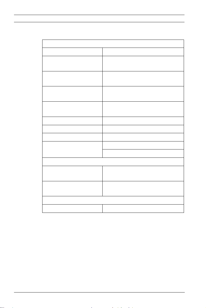
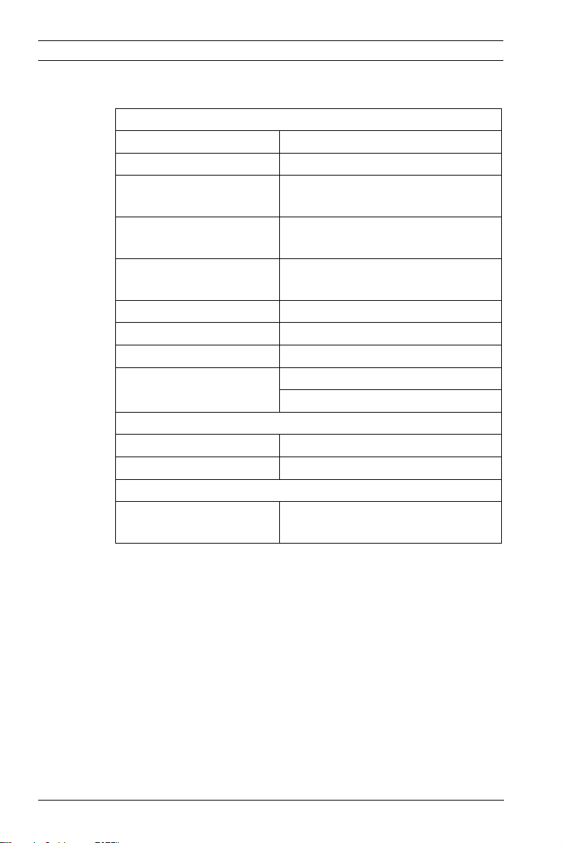
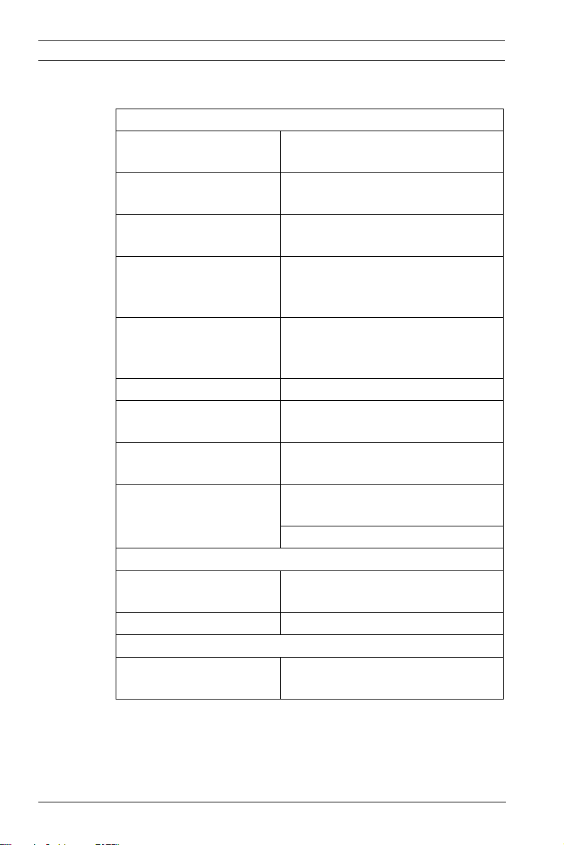
1.4 TECHNISCHE DATEN
Elektrische Kenndaten
Netzteiltyp Linear (empfohlen) Betriebsspannungsbereich5– 16VDC
Maximaler Eingangsstrom
Sabotageausgang Open Collector, low-aktiv,
Max. Kabellänge bis zum Kontroller
Ausgangsmodulation 26-Bit-Wiegand Kartenleseabstand* 12 cm HF-Modulation ASK Behördliche Zulassungen USA: UL 294 und FCC Teil 15B
Umgebungskenndaten
Betriebstemperaturbereich-31 °C bis 63 °C
Luftfeuchtigkeit während des Betriebs
Abmessungen
Höhe x Breite x Tiefe 109,91 x 74,91 x 15 mm
* Gemessen mit Bosch berührungslosem Ausweis (Artikelnr.
ACD-ATR11ISO) oder einer gleichwertigen Komponente. Die
Reichweite hängt auch von der elektrischen Umgebung und/
oder der Nähe zu Metall ab.
Standby: 35 mA
Lesen: 100 mA
maximaler Ausgangsstrom 16 mA
150 m
Europa: CE-Zulassung
0 bis 95 % (nicht kondensierend)
Für die Verwendung im Freien geeignet
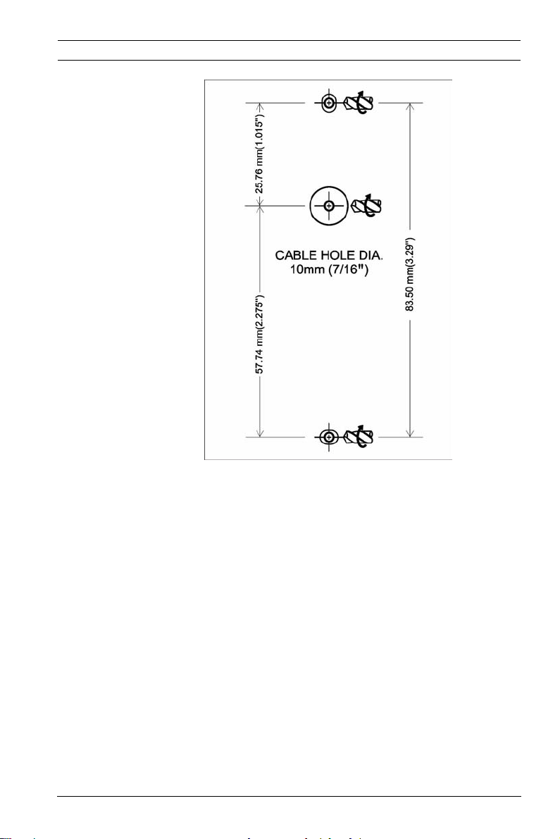
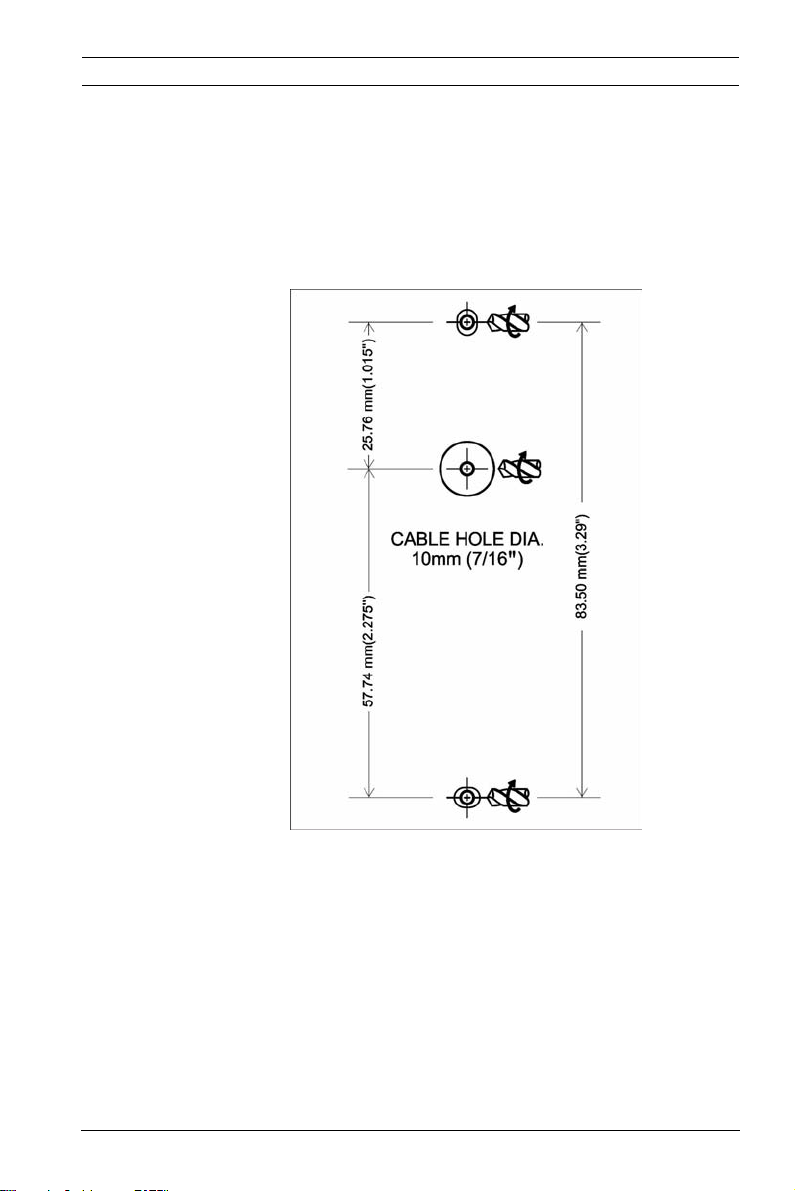
1.5 MONTAGEDARSTELLUNG
| V 1.4 | 2010.04 Installationshandbuch Bosch Access Systems GmbH
ARD-AYH12 Installationshandbuch | de 11
Bosch Access Systems GmbH Installationshandbuch | V 1.4 | 2010.04

12 de | Technischer Kundendienst ARD-AYH12
2 Technischer Kundendienst
Europa, Naher Osten, Afrika:
Bosch Security Systems B.V.
P.O. Box 80002
5600 JB Eindhoven, Niederlande
Telefon: +31(0)402783955
Fax: +31(0)402786668
de.securitysystems@bosch.com
http://www.boschsecurity.com
Amerika:
Bosch Security Systems
130 Perinton Parkway
Fairport, New York, 14450, USA
Telefon: +1 585 223 4060
Fax: +1 800 289 0096
security-sales@us.bosch.com
http://www.boschsecurity.us
Asien/Pazifik:
Bosch Security Systems Pte Ltd.
38C Jalan Pemimpin
Singapore 577180
Telefon: +65 6319 3450
Fax: +65 6319 3499
apr.securitysystems@bosch.com
http://www.boschsecurity.com
| V 1.4 | 2010.04 Installationshandbuch Bosch Access Systems GmbH

ARD-AYH12 Table of Contents | en 13
Table of Contents
1 Installation Manual 14
1.1 MOUNTING INSTRUCTIONS 14
1.2 WIRING INSTRUCTIONS 15
1.3 OPERATION INSTRUCTIONS 16
1.4 TECHNICAL SPECIFICATIONS 18
1.5 MOUNTING DIAGRAM 18
2 Technical Support 20
Bosch Access Systems GmbH Installation manual | V 1.4 | 2010.04

14 en | Installation Manual ARD-AYH12
1 Installation Manual
The ARD-AYH12 is a RFID proximity card reader to be installed
for use with access control systems.
This installation manual contains the following information:
– Mounting Instructions
– Wiring Instructions
– Operation Instructions
– Technical Specifications
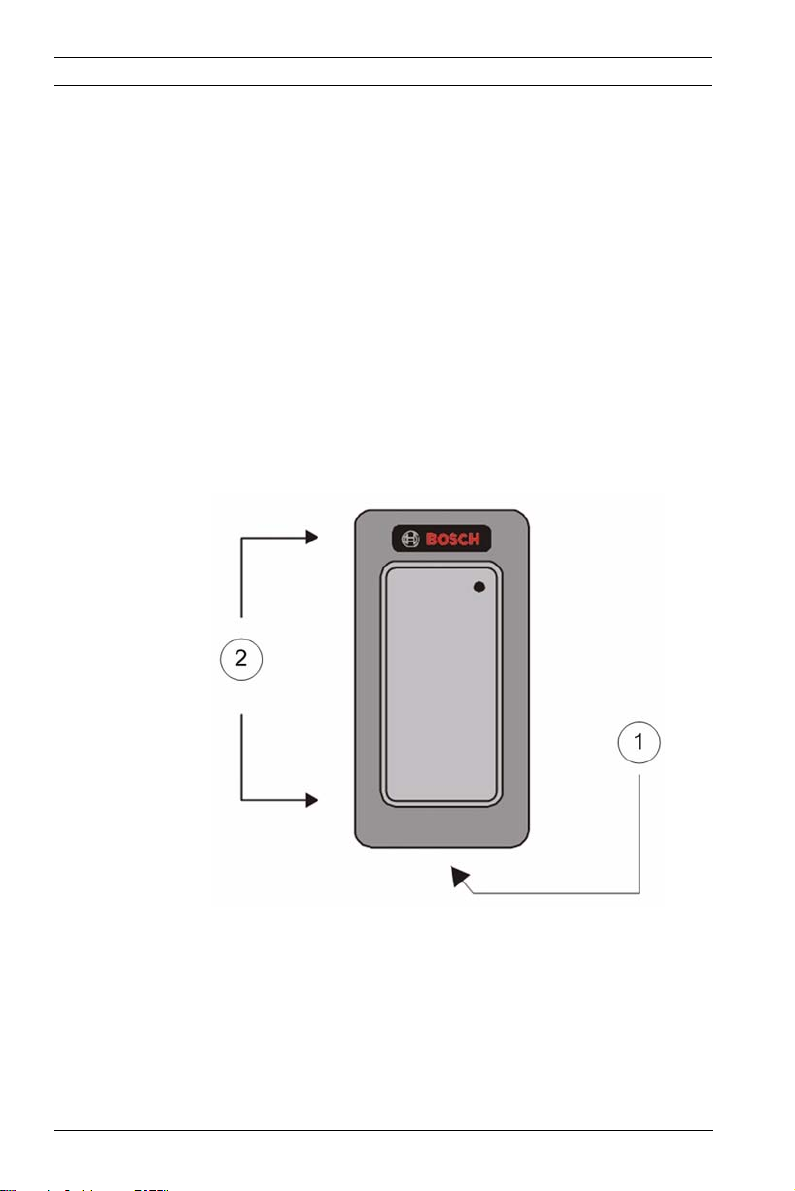
1.1 MOUNTING INSTRUCTIONS
1 = To remove the top cover you need to unscrew the top
cover screw located on the bottom of the reader.
2 = Remove the top cover to reveal the screw holes for
mounting.
Mount the reader with the appropriate screws (not supplied) as
indicated on the template.
To mount the reader, perform the following:
| V 1.4 | 2010.04 Installation manual Bosch Access Systems GmbH
ARD-AYH12 Installation Manual | en 15
1. Determine an appropriate mounting position for the reader.
2. Peel off the back of the self-stick mounting label template
included with the unit and place at the desired mounting
position. If you do not have the self-stick mounting
template label, refer to the Mounting Diagrams in this
manual for the dimensions.
3. Using the template as a guide, drill the holes (hole size is
indicated on mounting template) for mounting the reader
to the surface.
4. Drill a
7/16" (10 mm) hole for the cable. If mounting on
metal, place a grommet or electrical tape around the edge
of the hole.
5. Route the interface cable from the reader to the controller. A linear type power supply is recommended
NOTICE!
Card readers are to be used with a listed access control unit whose power supply is UL Listed Class 2 or equivalent.
1.2 WIRING INSTRUCTIONS
The ARD-AYH12 is supplied with an 18 inch (45 cm) pigtail,
having a 6-conductor cable.
To connect the reader to the controller, perform the following
steps:
1. Prepare the reader cable by cutting the cable jacket back 1
1/4 inches (3,4 cm) and strip the wires 1/2 inch (1,3 cm).
2. Prepare the controller cable by cutting the cable jacket back 1 1/4 inches (3,4 cm) and strip the wires 1/2 inch (1,3 cm).
3. Splice the reader pigtail wires to the corresponding controller wires and cover each connection with insulating tape.
Bosch Access Systems GmbH Installation manual | V 1.4 | 2010.04

16 en | Installation Manual ARD-AYH12
4. If the tamper output is being utilized, connect the purple wire to the correct input on the controller.
5. Trim and cover all conductors that are not used.
The table below shows how you should wire the reader to the controller.
Color Wiegand Output
Red DC + Input Black Ground White Data 1 Green Data 0 Brown LED Control Purple Tamper
Cable Notes:
1. The individual wires coming out of the reader are color coded according to the recommended Wiegand standard.
2. When using a separate power supply for the reader, this supply and the controller's power supply must have a common ground.
3. The cable shield wire on the reader should be attached to
an earth ground (best) or signal ground connection at the
panel or power supply end of the cable. This configuration
is best for shielding the reader cable from external
interference.
1.3 OPERATION INSTRUCTIONS
The reader should be tested after wiring it to a power supply
and the controller.
Do this by performing the following steps:
1. Power up the reader. The LED and beeper will activate three times. This indicates that the reader is working properly.
| V 1.4 | 2010.04 Installation manual Bosch Access Systems GmbH

ARD-AYH12 Installation Manual | en 17
2. Present the appropriate type of proximity card to the reader. The LED will momentarily flash green and a short beep will be emitted. This indicates that the card was read properly by the Proximity Card Reader.
3. After the card data is processed by the controller, the controller can then turn the LED green. Refer to the controller description of the LED operation if the reader LED is controlled by the controller.
Bosch Access Systems GmbH Installation manual | V 1.4 | 2010.04
18 en | Installation Manual ARD-AYH12
1.4 TECHNICAL SPECIFICATIONS
Electrical Characteristics
Power Supply Type Linear type recommended Operating Voltage Range 5 - 16 VDC Maximum Input Current Standby: 35 mA
Read: 100 mA
Tamper Output Open collector, active low, max
sink current 16 mA
Max Cable Distance to Controller
Output modulation 26-bit Wiegand Card read distance* 4.72 inch (12 cm) RF Modulation ASK Regulatory Approvals USA: UL 294 & FCC Part 15B
Environmental Characteristics
Operating Temp. Range -25°F to 145°F (-31°C to 63°C ) Operating Humidity 0 to 95% (non condensing)
Dimensions
Height x Widht X Depth 4.33 x 2.95 x 0.59 inch
500 ft. (150 meters)
Europe: CE Listed
(109.91 x 74.91 x 15 mm)
* Measured using Bosch Proximity Card (P/N ACD-ATR11ISO)
or equivalent. Range also depends on electrical environment
and/or proximity to metal.
Suitable for Outdoor Use
1.5 MOUNTING DIAGRAM
| V 1.4 | 2010.04 Installation manual Bosch Access Systems GmbH

ARD-AYH12 Installation Manual | en 19
Bosch Access Systems GmbH Installation manual | V 1.4 | 2010.04

20 en | Technical Support ARD-AYH12
2 Technical Support
Europe, Middle East, Africa:
Bosch Security Systems B.V.
P.O. Box 80002
5600 JB Eindhoven, The Netherlands
Phone: +31(0)402783955
Fax: +31(0)402786668
emea.securitysystems@bosch.com
http://www.boschsecurity.com
America:
Bosch Security Systems
130 Perinton Parkway
Fairport, New York, 14450, USA
Phone: +1 585 223 4060
Fax: +1 800 289 0096
security-sales@us.bosch.com
http://www.boschsecurity.us
Asia Pacific:
Bosch Security Systems Pte Ltd.
38C Jalan Pemimpin
Singapore 577180
Phone: +65 6319 3450
Fax: +65 6319 3499
apr.securitysystems@bosch.com
http://www.boschsecurity.com
| V 1.4 | 2010.04 Installation manual Bosch Access Systems GmbH

ARD-AYH12 Índice | es 21
Índice
1 Manual de Instalación 22
1.1 INSTRUCCIONES DE MONTAJE 22
1.2 INSTRUCCIONES DE CABLEADO 23
1.3 INSTRUCCIONES DE OPERACION 25
1.4 ESPECIFICACIONES TÉCNICAS 26
1.5 DIAGRAMA DE MONTAJE 27
2 Asistencia técnica 28
Bosch Access Systems GmbH Manual de instalación | V 1.4 | 2010.04
22 es | Manual de Instalación ARD-AYH12
1 Manual de Instalación
El ARD-AYH12 es una lectora de tarjetas de proximidad RFID
que se instala y se utiliza junto con sistemas de control de
accesos.
Este manual de instalación contiene la siguiente información:
– Instrucciones de Montaje
– Instrucciones de Cableado
– Instrucciones de Uso
– Especificaciones Técnicas
1.1 INSTRUCCIONES DE MONTAJE
1 = Para retirar la tapa superior debe desatornillar el tornillo
de la tapa superior situado en la parte inferior de la
lectora.
2 = Retire la tapa superior para acceder a los orificios de los
tornillos de montaje.
| V 1.4 | 2010.04 Manual de instalación Bosch Access Systems GmbH
ARD-AYH12 Manual de Instalación | es 23
Fije la lectora con los tornillos adecuados (no incluidos), tal y
como se indica en la plantilla.
Para montar la lectora, siga los pasos siguientes:
1. Determine la posición más adecuada para el montaje de la lectora.
2. Retire la parte trasera de la plantilla de montaje
autoadhesiva que se suministra junto con la unidad y
colóquela en la posición de montaje escogida. Si no
dispone de la plantilla de montaje autoadhesiva, consulte
los diagramas de montaje que se incluyen con el manual
para obtener información acerca de las dimensiones.
3. Utilice la plantilla para guiarse y perfore los orificios (el
tamaño de los mismos está indicado en la plantilla de
montaje) para fijar la lectora a la superficie.
4. Perfore un orificio de
10 mm (7/16 pulg.) para el cable. Si
el montaje se realiza en una superficie metálica, coloque
una arandela o cinta aislante en el borde del orificio.
5. Pase los cables de interfaz desde la lectora hasta el controlador. Se recomienda utilizar una fuente de alimentación lineal.
¡NOTA!
Las lectoras de tarjetas deben utilizarse con unidades de control de accesos registrados con fuentes de alimentación con certificado UL de clase 2 o equivalente.
1.2 INSTRUCCIONES DE CABLEADO
El ARD-AYH12 se entrega con un cable de conexión flexible
(pigtail) de 45 mm (18 pulg.) que contiene 6 cables
conductores.
Para conectar la lectora al controlador, complete los siguientes
pasos:
1. Prepare el cable de la lectora: corte aislante y pele
Bosch Access Systems GmbH Manual de instalación | V 1.4 | 2010.04
1,3 cm (0,50 pulg.) de los cables.
3,4 cm (1,25 pulg.) del

24 es | Manual de Instalación ARD-AYH12
2. Prepare el cable del controlador: corte 3,4 cm (1,25 pulg.) del aislante y pele
1,3 cm (0,50 pulg.) de los cables.
3. Realice un empalme entre los cables conductores del cable
de conexión flexible (pigtail) de la lectora y los cables
correspondientes del controlador y, a continuación,
proteja todas las conexiones con cinta aislante.
4. Si utiliza la salida antisabotaje, conecte el cable púrpura a la entrada correspondiente del controlador.
5. Recorte y proteja todos los cables conductores que no se utilicen.
La siguiente tabla muestra cómo conectar la lectora al controlador.
Color Salida Wiegand
Rojo Entrada de CC+ Negro Toma de tierra Blanco Data 1 Verde Data 0 Marrón Control de LED Púrpura Antisabotaje
Notas de los Cables:
1. Cada uno de los cables que salen de la lectora posee un color de acuerdo con la codificación recomendada por el protocolo Wiegand.
2. Si se utiliza una fuente de alimentación independiente para la lectora, dicha fuente de alimentación y la del controlador deben compartir la misma toma de tierra.
3. Se recomienda que el hilo de blindaje del cable de la
lectora se conecte a una toma de tierra o, en su defecto, a
un retorno de tierra del circuito de señal del panel o al
extremo del cable de la fuente de alimentación. Ésta es la
configuración más adecuada para proteger el cable de la
lectora frente a interferencias externas.
| V 1.4 | 2010.04 Manual de instalación Bosch Access Systems GmbH

ARD-AYH12 Manual de Instalación | es 25
1.3 INSTRUCCIONES DE OPERACION
Se debe probar la lectora después de conectarla a la fuente de
alimentación y el controlador.
Para ello, complete los siguientes pasos:
1. Encienda la lectora. El LED se iluminará tres veces y el zumbador emitirá tres pitidos. Esto indica que la lectora funciona correctamente.
2. Pase la tarjeta de proximidad correspondiente por la lectora. Por un momento, el LED parpadea de color verde y se emite un pitido corto. Esto indica que la Lectora de Tarjetas de Proximidad ha leído la tarjeta correctamente.
3. Una vez que el controlador ha procesado los datos de la tarjeta, el LED vuelve al color verde. Consulte la descripción de operación del LED incluida con el controlador en caso de que éste gestione el LED de la lectora.
Bosch Access Systems GmbH Manual de instalación | V 1.4 | 2010.04
26 es | Manual de Instalación ARD-AYH12
1.4 ESPECIFICACIONES TÉCNICAS
Características Eléctricas
Tipo de Fuente de Alimentación
Rango de Tensión de Operación
Corriente de Entrada Máxima
Salida Antisabotaje Colector abierto, activo bajo,
Distancia Máxima del Cable hasta el Controlador
Modulación de salida Wiegand de 26 bits Distancia de lectura de
tarjetas*
Modulación de
Radiofrecuencia
Aprobaciones
Normativas
Características Medioambientales
Rango de Temperatura de Operación
Humedad de Operación De 0 a 95% (sin condensación)
Dimensiones
Altura x Anchura x Profundidad
Tipo lineal (recomendada)
5 - 16 VCC
Reposo: 35 mA
Lectura: 100 mA
corriente de absorción máxima de
16 mA
150 metros (500 pies)
12 cm (4,72 pulg.)
ASK
EE.UU.: UL 294 y FCC, apartado 15B
Europa: Certificado CE
De -31 °C a 63 °C (de -25 °F a
145 °F)
109,91 x 74,91 x 15 mm (4,33 x
2,95 x 0,59 pulg.)
* Medición realizada con una tarjeta de proximidad Bosch
(núm. de ref. ACD-ATR11ISO) o un dispositivo equivalente. La
distancia también varía en función del entorno eléctrico y la
proximidad de elementos metálicos.
| V 1.4 | 2010.04 Manual de instalación Bosch Access Systems GmbH
ARD-AYH12 Manual de Instalación | es 27
Apto para uso en exteriores
1.5 DIAGRAMA DE MONTAJE
Bosch Access Systems GmbH Manual de instalación | V 1.4 | 2010.04
Loading...