


 Loading...
ARD-AYZ12
|
|
|
|
|
|
|
|
|
|
|
|
en |
Installation manual |
||
de |
Installationshandbuch |
||
zh |
|
||
nl |
Installatiehandleiding |
||
es |
Manual de Instalación |
||

ARD-AYZ12 |
3 |
|
|
English
Deutsch
Nederlands
Español latinoamericano
Bosch Sicherheitssysteme GmbH |
| V 1.2 | 2009.09 |
4 |
ARD-AYZ12 |
|
|
| V 1.2 | 2009.09 |
Bosch Sicherheitssysteme GmbH |

ARD-AYZ12 |
Installation Manual | en |
5 |
|
|
|
Installation Manual
This installation manual contains the following information:
-Mounting Instructions
-Wiring Instructions
-Operation Instructions
-Technical Specifications
MOUNTING INSTRUCTIONS
Installation Kit
The installation kit comprises of the following items that are to be used during the installation procedure:
-One installation template
-Four pan head screws & wall plugs
-One L shaped security screw tool
-Three security screws
Mount the reader with the appropriate screws (not supplied) as indicated on the template.
To mount the reader, perform the following:
1.Determine an appropriate mounting position for the reader.
2.Peel off the back of the self-stick mounting label template included with the unit and place at the desired mounting position. If you do not have the self-stick mounting template label, refer to the Mounting Diagrams in this manual for the dimensions. When mounting the reader, you must remove the snap-off cover to access the screw holes - see Figure 1. Installing the unit on metal surfaces will reduce the read range considerably. to decrease the affect of the metal surface use the BOSCH ARD-MPZ02 spacer (sold separately) as described in Figure 2 for a max range of 17 inch (43 cm).
3.Using the template as a guide, drill the holes (hole size is indicated on mounting template) for mounting the reader or spacer to the surface.
4.Drill a 7/16" (10 mm) hole for the cable. If mounting on metal, place a grommet or electrical tape around the edge of the hole and use the ARD-MPZ02 spacer.
5.Route the interface cable from the reader to the controller. A linear type power supply is recommended
Bosch Sicherheitssyteme GmbH |
| V 1.2 | 2009.09 |

6 en | Installation Manual |
ARD-AYZ12 |
|
|
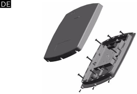
Figure 1 Removing the Top Cover
The figure obove shows the front view of the ARD-AYZ12 LongRange Reader.
When installing the reader, you must remove the snap-off cover to access the screw holes. The reader must be mounted with the appropriate screws (not supplied), as described in the template provided.
Installing the unit on metal surfaces will reduce the read range considerably, to decrease the affect of the metal surface use BOSCH’s ARD-MPZ02 Spacer (sold separately) as described in the image below for a max range of 43 cm (17 inch) - refer to
Figure 2.
| V 1.2 | 2009.09 |
Bosch Sicherheitssyteme GmbH |

ARD-AYZ12 |
Installation Manual | en |
7 |
|
|
|
Figure 2 Installing the unit with the ARD-MPZ02 spacer
WIRING INSTRUCTIONS
The ARD-AYZ12 is supplied with an 18 inch (45 cm) pigtail, having a 6-conductor cable.
To connect the reader to the controller, perform the following steps:
1.Prepare the reader cable by cutting the cable jacket back 1 1/4 inches (3,4 cm) and strip the wires 1/2 inch (1,3 cm).
2.Prepare the controller cable by cutting the cable jacket back 1 1/4 inches (3,4 cm) and strip the wires 1/2 inch (1,3 cm).
3.Splice the reader pigtail wires to the corresponding controller wires and cover each connection with insulating tape.
4.If the tamper output is being utilized, connect the purple wire to the correct input on the controller.
5.Trim and cover all conductors that are not used.
Bosch Sicherheitssyteme GmbH |
| V 1.2 | 2009.09 |

8 en | Installation Manual |
ARD-AYZ12 |
|
|
The table below shows how you should wire the reader to the |
|
controller. |
|
Color |
Wiegand Output |
Red |
DC + Input |
Black |
Ground |
White |
Data 1 |
Green |
Data 0 |
Brown |
LED Control |
Purple |
Tamper |
Cable Notes:
1.The individual wires coming out of the reader are color coded according to the recommended Wiegand standard.
2.When using a separate power supply for the reader, this supply and the controller's power supply must have a common ground.
3.The cable shield wire on the reader should be attached to an earth ground (best) or signal ground connection at the panel or power supply end of the cable. This configuration is best for shielding the reader cable from external interference.
OPERATION INSTRUCTIONS
The reader should be tested after wiring it to a power supply and the controller.
Do this by performing the following steps:
1.Power up the Reader. The LED flashes green on power up (it may flash orange), and the Beeper sounds twice, at which point it begins an auto-calibration procedure, this can take up to two seconds, when the calibration is complete a third beep will sound, thus indicating that the Reader is working properly. The LED returns to its idle state (red).
2.Present the appropriate type of proximity card to the reader. The LED will momentarily flash green and a short beep will be emitted. This indicates that the card was read properly by the Proximity Card Reader.
3.After the card data is processed by the controller, the controller can then turn the LED green. Refer to the controller description of the LED operation if the reader LED is controlled by the controller.
| V 1.2 | 2009.09 |
Bosch Sicherheitssyteme GmbH |

ARD-AYZ12 |
Installation Manual | en 9 |
|
|
|
|
|
TECHNICAL SPECIFICATIONS |
|
|
|
|
|
Electrical Characteristics |
|
|
|
|
|
Power Supply Type |
Linear type recommended |
|
|
|
|
Operating Voltage Range |
10 - 16 VDC |
|
|
|
|
Absolute Maximum (non- |
18 VDC |
|
operating) |
|
|
|
|
|
Maximum Input Current |
Standby: 280 mA |
|
|
Read: 330 mA |
|
|
|
|
Tamper Output |
Open collector, active low, max |
|
|
sink current 30 mA |
|
|
|
|
Max Cable Distance to |
500 ft. (150 meters) |
|
Controller |
|
|
|
|
|
Output modulation |
26-bit Wiegand |
|
|
|
|
Card read distance* |
23.6 inch (60 cm) |
|
|
|
|
Environmental Characteristics |
|
|
|
|
|
Operating Temp. Range |
-22°F to 145°F (-30°C to 63°C ) |
|
|
|
|
Operating Humidity |
0 to 95% (non condensing) |
|
|
|
|
Environment class |
IP 54 |
|
|
|
|
Dimensions |
|
|
|
|
|
Height x Width X Depth |
11.81 x 11.81 x 1.0 inch |
|
|
(300 x 300 x 25.4 mm) |
|
|
|
|
Weight |
2.35 Lbs. (1066 g) |
|
|
|
* Measured using Bosch Proximity Card (P/N ACD-ATR11ISO) or equivalent. Range also depends on electrical environment and/ or proximity to metal.
Suitable for Outdoor Use
Bosch Sicherheitssyteme GmbH |
| V 1.2 | 2009.09 |
10 en | Installation Manual |
ARD-AYZ12 |
|
|
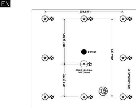
MOUNTING DIAGRAM
| V 1.2 | 2009.09 |
Bosch Sicherheitssyteme GmbH |
ARD-AYZ12 |
Installationshandbuch | de 11 |
|
|
Installationshandbuch
Dieses Installationshandbuch enthält folgende Informationen:
-Montageanleitung
-Verkabelungsanleitung
-Bedienungsanleitung
-Technische Daten
MONTAGEANLEITUNG
Montagesatz
Im Montagesatz sind folgende Komponenten für die Montage enthalten:
-Eine Montageschablone
-Vier Flachkopfschrauben und Wanddübel
-Ein L-förmiges Werkzeug für Sicherheitsschrauben
-Drei Sicherheitsschrauben
Montieren Sie den Leser wie auf der Schablone angegeben mit den entsprechenden Schrauben (nicht im Lieferumfang enthalten).
Gehen Sie zur Montage des Lesers wie folgt vor:
1.Legen Sie eine geeignete Montageposition für den Leser fest.
2.Ziehen Sie die Rückseite der mit dem Gerät mitgelieferten selbstklebenden Montagemarkierungsschablone ab, und bringen Sie die Schablone an der gewünschten Montageposition an. Wenn Sie über keine selbstklebende Montagemarkierungsschablone verfügen, können Sie die Abmessungen aus den Montagedarstellungen in diesem Handbuch entnehmen. Bei der Montage des Lesers muss für den Zugang zu den Schraubenöffnungen die Schnappabdeckung entfernt werden (siehe Bild 3). Wenn das Gerät auf Metalloberflächen montiert wird, verringert sich die Lesereichweite erheblich. Mit dem separat angebotenen BOSCH ARD-MPZ02 Distanzstück (siehe Bild 4) wird die Wirkung der Metalloberfläche verringert und eine maximale Reichweite von 43 cm erreicht.
3.Bohren Sie die Löcher (der Bohrungsdurchmesser ist auf der Montageschablone angegeben) für die Montage des Lesers bzw. des Distanzstücks auf der entsprechenden Oberfläche.
4.Bohren Sie ein Loch mit 10 mm Durchmesser für das Kabel. Bei der Montage auf Metall ist die Bohrungskante mit einer Schutzmanschette oder mit Isolierband zu versehen und das ARD-MPZ02 Distanzstück zu verwenden.
Bosch Sicherheitssyteme GmbH |
| V 1.2 | 2009.09 |
12 de | Installationshandbuch |
ARD-AYZ12 |
|
|
5.Führen Sie das Schnittstellenkabel vom Leser zum Kontroller. Es wird empfohlen, ein Netzteil mit linearer Spannungsregelung zu verwenden.
Bild 3 Entfernen der oberen Abdeckung
Die Abbildung oben zeigt die Vorderansicht des ARD-AYZ12 Lesers mit großer Reichweite.
Bei der Montage des Lesers muss für den Zugang zu den Schraubenöffnungen die Schnappabdeckung entfernt werden. Der Leser muss mit den entsprechenden Schrauben (nicht im Lieferumfang enthalten) wie auf der mitgelieferten Schablone angegeben montiert werden.
Wenn das Gerät auf Metalloberflächen montiert wird, verringert sich die Lesereichweite erheblich. Mit dem separat angebotenen BOSCH ARD-MPZ02 Distanzstück (siehe Abbildung unten) wird die Wirkung der Metalloberfläche verringert und eine maximale Reichweite von 43 cm erreicht (siehe Bild 4).
| V 1.2 | 2009.09 |
Bosch Sicherheitssyteme GmbH |

ARD-AYZ12 |
Installationshandbuch | de 13 |
|
|
Bild 4 Installieren des Geräts mit dem ARD-MPZ02 Distanzstück
VERKABELUNGSANLEITUNG
Der ARD-AYZ12 wird mit einem 45 cm langen 6-adrigen Anschlusskabel geliefert.
Gehen Sie zum Anschließen des Lesers an den Kontroller wie folgt vor:
1.Bereiten Sie das Leser-Kabel vor, indem Sie den Kabelmantel auf einer Länge von 3,4 cm entfernen und die Drähte auf einer Länge von 1,3 cm abisolieren.
2.Bereiten Sie das Kontroller-Kabel vor, indem Sie den Kabelmantel auf einer Länge von 3,4 cm entfernen und die Drähte auf einer Länge von 1,3 cm abisolieren.
3.Verbinden Sie die Drähte der Anschlussleitung des Lesers mit den entsprechenden Drähten des Controller-Kabels, und isolieren Sie alle Verbindungsstellen mit Isolierband.
4.Wenn der Sabotageausgang verwendet wird, schließen Sie den violetten Draht an den entsprechenden Eingang am Controller an.
Bosch Sicherheitssyteme GmbH |
| V 1.2 | 2009.09 |

14 de | Installationshandbuch |
ARD-AYZ12 |
|
|
5.Schneiden Sie alle nicht verwendeten Leiter zurück, und isolieren Sie sie entsprechend.
In der nachfolgenden Tabelle ist die Verdrahtung des Lesers mit dem Kontroller angegeben.
Farbe |
Wiegand-Ausgang |
Rot |
DC+-Eingang |
Schwarz |
Masse |
Weiß |
Daten 1 |
Grün |
Daten 0 |
Braun |
LED-Steuerung |
Violett |
Sabotage |
Hinweise zur Verkabelung:
1.Die einzelnen Adern des Lesers sind nach dem empfohlenen Wiegand-Standard farbcodiert.
2.Bei Verwendung eines separaten Netzteils für den Leser muss für dieses Netzteil und das Netzteil des Kontrollers eine gemeinsame Masse vorhanden sein.
3.Die Abschirmung ist an einen Erdanschluss (optimale Lösung) bzw. Erdleiter am Panel oder auf der Netzteilseite des Kabels anzuschließen. Diese Konfiguration ist für die Abschirmung des Leser-Kabels gegen externe Störungen die beste Lösung.
BEDIENUNGSANLEITUNG
Nach der Verkabelung mit einem Netzteil und dem Kontroller ist die Funktion des Lesers zu überprüfen.
Gehen Sie dabei wie folgt vor:
1.Schalten Sie den Leser ein. Die LED blinkt nach dem Einschalten grün (evtl. auch orange), und der akustische Signalgeber ertönt zweimal. Danach wird mit der automatischen Kalibrierung begonnen. Dieser Vorgang kann bis zu zwei Sekunden dauern. Wenn die Kalibrierung abgeschlossen ist, ertönt ein dritter Signalton, der die ordnungsgemäße Funktion des Lesers signalisiert. Die LED signalisiert wieder den inaktiven Zustand (rot).
2.Lesen Sie den entsprechenden berührungslosen Ausweistyp mit dem Leser ein. Die LED blinkt kurz grün, und es ertönt ein kurzes akustisches Signal. Damit wird angezeigt, dass die Karte ordnungsgemäß vom
| V 1.2 | 2009.09 |
Bosch Sicherheitssyteme GmbH |
Loading...