


 Loading...
Access Easy Controller 2.1
APC-AEC21-UPS1 | AEC-AEC21-EXT1
en Hardware Manual

Access Easy Controller 2.1 |
Table of Contents | en |
3 |
|
|
|
Table of Contents
1 |
Before You Begin |
7 |
1.1 |
General |
7 |
1.2 |
Terminologies |
7 |
|
|
|
2 |
Overview of Access Easy Controller 2.1 |
8 |
2.1 |
Architecture of Access Easy Controller 2.1 |
8 |
2.2 |
Basic Functions in Access Easy Controller 2.1 |
8 |
2.3 |
Basic Access Easy Controller 2.1 |
9 |
|
|
|
3 |
System Layout |
11 |
3.1 |
System Specifications |
12 |
|
|
|
4 |
The CPU Board |
15 |
4.1 |
Component Layout of the CPU Board |
16 |
4.1.1 |
Other Components |
18 |
|
|
|
5 |
4-Reader Board |
19 |
5.1 |
Technical Overview of 4-Reader Board |
19 |
5.1.1 |
Component Layout of 4-Reader Board |
19 |
5.1.2 |
Reader Connectors |
20 |
5.1.3 |
Input Connectors |
21 |
5.1.4 |
Output Connectors |
22 |
5.1.5 |
15 VDC Input Termination |
23 |
5.1.6 |
RS232 |
24 |
5.1.7 |
RS485 |
24 |
5.1.8 |
Tamper and Main Power Fail |
24 |
5.1.9 |
LED Indicators |
25 |
5.1.10 |
Reset Button |
25 |
5.1.11 |
End-of-Line Setting |
25 |
5.1.12 |
Address Setting Switch |
25 |
5.1.13 |
Factory Default Setting |
26 |
|
|
|
6 |
8-Input-Output Board |
28 |
6.1 |
Technical Overview of 8-Input-Output Board |
28 |
6.1.1 |
Component Layout of 8-Input-Output Board |
28 |
6.1.2 |
Input Connectors |
29 |
6.1.3 |
Output Connectors |
30 |
6.1.4 |
15 VDC Input Termination |
32 |
6.1.5 |
RS232 |
32 |
6.1.6 |
RS485 |
32 |
6.1.7 |
Tamper and Main Power Fail |
33 |
6.1.8 |
LED Indicators |
33 |
6.1.9 |
Reset Button |
33 |
6.1.10 |
End-of-Line Setting |
34 |
6.1.11 |
Address Setting Switch |
34 |
Robert Bosch (SEA) Pte Ltd |
Hardware Manual |
F.01U.122.796 | 1.0.5 | 2011.09 |

4 en | Table of Contents Access Easy Controller 2.1
7 |
Power Supply Unit |
35 |
7.1 |
Layout of Power Supply Unit |
35 |
7.2 |
Technical Specification of Power Supply Unit with Input Power of 100~240 VAC |
36 |
7.3 |
Power Supply Requirement and Connection |
36 |
7.4 |
Current Consumption |
36 |
7.5 |
Connection in the Main Controller |
37 |
8 |
Access Easy Extension Unit |
38 |
8.1 |
Upgrading AEC2.1 to Support Additional Four 4-Reader Boards and Four 8-IO Boards |
40 |
|
|
|
9 |
How to Install Reader and Field Devices |
41 |
9.1 |
HID MiniProx Reader |
43 |
9.2 |
HID ProxPoint Reader |
45 |
9.3 |
HID ProxPro Reader |
46 |
9.4 |
HID ProxPro Reader with Keypad |
48 |
9.5 |
Field Devices using IO Board |
50 |
9.5.1 |
Wiring Diagram for Supervised Inputs |
51 |
|
|
|
10 |
How to Install the Access Easy Controller 2.1 |
52 |
10.1 |
Preliminary |
52 |
10.2 |
Mounting the Panel on a Concrete Wall |
52 |
10.3 |
Controller Installation |
54 |
|
|
|
11 |
Card Reader Keypad Functions |
56 |
11.1 |
Keypad Layout |
56 |
11.1.1 |
Keypad Functions |
56 |
11.2 |
Entry Operation |
57 |
11.2.1 |
Using Card + PIN Mode on a Keypad Reader |
57 |
11.2.2 |
Using Keypad in “Enable Keypad Only Operation” Mode |
57 |
11.2.3 |
Other Usage |
58 |
11.2.4 |
Changing PIN Code |
58 |
11.2.5 |
Entry and Arm/Disarm Reader |
59 |
|
|
|
12 |
Common Alarm Output |
62 |
12.1 |
Overview |
62 |
12.2 |
Alarm (All Input Points) |
62 |
12.3 |
Door Forced Open and Door Held Open |
62 |
12.4 |
Panel AC Failure |
63 |
12.5 |
Controller Tamper |
63 |
12.6 |
Duress |
63 |
|
|
|
13 |
How to Set Up the Access Easy Controller 2.1 and the Computer |
64 |
13.1 |
Overview |
64 |
13.2 |
Configuring a Web Browser to Work with Access Easy Controller 2.1 |
65 |
13.3 |
Web Browser Set-up on a Windows Computer |
65 |
13.4 |
Install AEC2.1 Certificate on a Windows Computer |
70 |
13.5 |
How to Set Initial Controller Configuration |
74 |
F.01U.122.796 | 1.0.5 | 2011.09 |
Hardware Manual |
Robert Bosch (SEA) Pte Ltd |

Access Easy Controller 2.1 Table of Contents | en 5
14 |
Dial-In Networking |
76 |
14.1 |
Guidelines for Modem Installation - Not Investigated by UL |
76 |
14.2 |
Installing the Modem |
76 |
14.2.1 |
Modem Switch Settings |
78 |
14.3 |
Dial-in Security Features |
79 |
14.4 |
Controller Setup |
80 |
14.5 |
Handling of IP Addresses by Access Easy Controller 2.1 |
80 |
14.6 |
Changing the Dial-In IP Address |
81 |
14.7 |
Configuring a Windows Computer to Dial the Access Easy Controller 2.1 |
81 |
14.8 |
Handling Simultaneous Network and Dial-in Connections |
85 |
15 |
Restoring a Backup Copy of Database to the Access Easy Controller 2.1 |
86 |
15.1 |
Tools Needed |
86 |
15.2 |
Before Starting the Update |
86 |
15.3 |
Recovering Controller Database from a Windows Computer |
86 |
16 |
Entry and Arm/Disarm Reader |
88 |
16.1 |
Wiring diagram of a HID Compliant Entry and Arm/Disarm Reader |
90 |
|
|
|
17 |
Appendix A How to Install & Set the TCP/IP Address on a PC |
91 |
|
|
|
18 |
Appendix B Modem Setup |
95 |
18.1 |
Preparing the WAVECOM GSM Modem for AEC2.1 |
95 |
18.2 |
How to Test the GSM Modem |
97 |
|
|
|
19 |
Appendix C Detailed Wiring |
98 |
|
|
|
20 |
Appendix D Selecting A Correct Battery Size |
100 |
20.1 |
Battery Specification for Access Easy Controller 2.1 |
100 |
|
|
|
21 |
Appendix E Troubleshooting |
102 |
21.1 |
Login Problems |
102 |
21.2 |
Network Connectivity Problems |
103 |
|
|
|
22 |
Appendix F Frequently Asked Questions |
109 |
22.1 |
General Questions |
109 |
22.2 |
Controller Questions |
111 |
22.3 |
Reader and Door Questions |
112 |
22.4 |
Inputs and Outputs |
114 |
22.5 |
Network Question |
114 |
|
|
|
23 |
Appendix G Blank Configuration Form |
116 |
|
|
|
24 |
Appendix H Resetting to Factory Default |
118 |
24.1 |
Resetting to Factory Default |
119 |
Robert Bosch (SEA) Pte Ltd |
Hardware Manual |
F.01U.122.796 | 1.0.5 | 2011.09 |

6 en | Table of Contents Access Easy Controller 2.1
24.2 Resetting IP Address to Default IP Address 120
F.01U.122.796 | 1.0.5 | 2011.09 |
Hardware Manual |
Robert Bosch (SEA) Pte Ltd |

Access Easy Controller 2.1 Before You Begin | en 7
1 |
Before You Begin |
1.1 |
General |
|
Access Easy Controller is a web based security system that allows you to control and monitor |
|
access routes with flexibility and conveniences to suit individual needs. |
|
This hardware manual helps you understand the Access Easy Controller 2.1 and helps the |
|
system serve you better. Access Easy Controller is a solution invented for life. |
1.2 |
Terminologies |
|
The Access Easy Controller 2.1 Hardware Manual contains detailed information and |
|
connection diagrams for Access Easy Controller 2.1, its components, and peripheral field |
|
devices. |
The following terminologies are used to describe the components and peripheral field devices in Access Easy Controller 2.1 Hardware Manual.
Terminology |
Descriptions |
|
|
Access Easy Controller 2.1 |
Access Easy Controller 2.1 enclosure with PSU, CPU |
(hereinafter will be referred as |
board and an Interface board (4-Reader board). |
“AEC2.1”) |
|
|
|
Access Easy Extension Unit |
Access Easy Controller 2.1 enclosure with PSU and |
(hereinafter will be referred as |
space for 2x interface boards (4-Reader or 8-Input- |
“Extension Unit”) |
Output board) and a backup battery. |
|
|
4-Reader Board (hereinafter will be |
Interface board for Access Easy Controller 2.1 and |
referred as “4-Reader board”) |
Extension. The board supports 4 Wiegand readers |
|
and provides 8 input and 8 output connection ports |
|
for door control. |
|
|
8-Input-Output Board (hereinafter will |
Interface board for Access Easy Controller 2.1 and |
be referred as “8-IO board”) |
Extension. It supports 8 inputs and 8 outputs, |
|
fitting parts. |
|
|
CPU Board |
Access Easy CPU board. The CPU is the main |
|
controlling devise in Access Easy Controller 2.1 |
|
system. |
|
|
Power Supply Unit (hereinafter will be |
The Power Supply Unit used in Access Easy |
referred as “PSU”) |
Controller 2.1 has an input power of 100~240 VAC. |
|
|
EM Reader |
Access Reader 8000 Wiegand EM Prox. |
|
|
Robert Bosch (SEA) Pte Ltd |
Hardware Manual |
F.01U.122.796 | 1.0.5 | 2011.09 |
8 en | Overview of Access Easy Controller 2.1 Access Easy Controller 2.1
2 |
Overview of Access Easy Controller 2.1 |
||||
2.1 |
Architecture of Access Easy Controller 2.1 |
||||
|
|
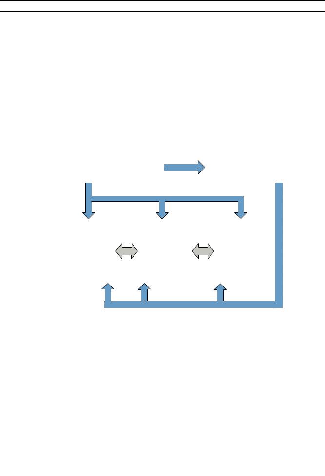
The basic architecture of an AEC2.1 system can be divided into two main building blocks, |
|||
|
|
namely the Power and the Function. The Power block provides the required power to all the |
|||
|
|
modules and sustains the system in times of AC power failure. The electrical input sources |
|||
|
|
vary according to individual electrical power standards in the country. |
|||
|
|
The Function block can be divided into three different modules namely the Software, the |
|||
|
|
Processor and the Interface module. These modules work together to define the system’s |
|||
|
|
characteristics and behaviors. Interactions between the modules are carried out through |
|||
|
|
standard RS232 and RS485 channels. Such architecture structure allows versatilities in |
|||
|
|
system designing and building. |
|
|
|
|
|
|
|
|
|
|
|
Power Module |
Charging |
Power Module |
|
|
|
(Power Supply Unit) |
(Back up Battery) |
|
|
|
|
|
|
||
|
|
|
|
|
|
|
|
|
|
|
|
|
Software Module |
|
|
|
|
|
(Firmware) |
|
|
|
|
|
|
|
Interface Module |
|
Interface Module |
|
Processing Module |
|
(Interface Boards, |
|
(Interface Boards, |
|
RS232 |
4-Reader Board/8- |
RS485 |
4-Reader Board/8- |
|
|
(CPU) |
||||
|
|
Input-Output |
|
Input-Output |
|
|
|
|
|
||
|
|
|
Board) |
|
Board) |
|
|
|
|
|
|
|
Battery Discharging during Power Failure |
|
|
|
Figure 2.1 Access Easy Controller 2.1 Architecture |
||
2.2 |
Basic Functions in Access Easy Controller 2.1 |
||
|
Based on hardware configuration and database setup, AEC2.1 offers all the features and |
||
|
functions available with high-end access controllers. |
||
– Door access control using card readers, or card reader and PIN code
– In and Out readers for high security areas
– Video verification for door access
– View Live and Playback videos
– Download event videos to PC
– Anti-passback control
– Alarm monitoring of reader controlled doors for Door Held and Door Forced conditions
– Alarm monitoring of non-reader doors and other inputs
– Manual door unlocking and locking
– Automatic door locking and unlocking based on schedules
– Automatic Arming and Disarming of input points
F.01U.122.796 | 1.0.5 | 2011.09 |
Hardware Manual |
Robert Bosch (SEA) Pte Ltd |
Access Easy Controller 2.1 Overview of Access Easy Controller 2.1 | en 9
|
– Lighting and output control based on schedules |
|
– Special scheduling option for holidays |
|
– Built-in reporting capabilities |
|
– Common alarm output for connection to intrusion alarm system |
|
AEC2.1 supports a wide range of applications, it is necessary you understand how to |
|
configure it and select the necessary hardware, such as card readers or additional input/ |
|
output boards. |
|
Unlike other access controllers, no special software is required on a host computer. The |
|
software needed to program and operate the AEC2.1 is built in the controller. Data entry and |
|
system monitoring functions are performed by connecting to the controller with a standard |
|
Web browser, such as Microsoft's Internet Explorer version 7.0. |
|
For more information on using the data entry and monitoring screens, refer to the AEC2.1 |
|
Software Manual. |
2.3 |
Basic Access Easy Controller 2.1 |
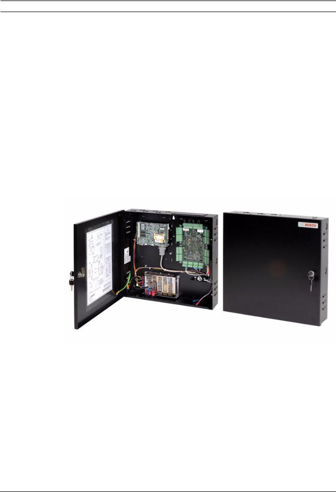
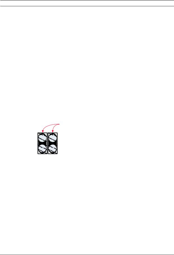
Figure 2.2 Access Easy Controller 2.1
The basic AEC2.1 system consists of a single metal enclosure with three components: CPU, 4- Reader board, and Power Supply Unit (PSU). Space is provided for a 12-volt standby battery to sustain the system in time of power failure. The PSU in the controller has an input power of 100~240 VAC. The enclosure is key locked and is equipped with a tamper switch to detect any tampering of the panel, and/or when the controller door is being opened.
In its minimum configuration, an AEC2.1 system supports one 4-Reader board. The board comes with, 4 card reader, 8 input, and 8 output ports to support all necessary hardware (door lock/strike outputs, door contact inputs and request-to-exit inputs). A full AEC2.1 system supports up to a maximum of 16 interface boards (eight 4-Reader boards and eight 8- IO boards). This allows the AEC2.1 system to support up to 32 card readers, 64 alarm type input and 64 controllable output points.
Robert Bosch (SEA) Pte Ltd |
Hardware Manual |
F.01U.122.796 | 1.0.5 | 2011.09 |
10 en | Overview of Access Easy Controller 2.1 |
Access Easy Controller 2.1 |
|
|
CPU Board - The CPU board contains a microprocessor, RAM memory and all necessary electronic circuitry to interact with other circuit boards. The CPU board also contains the hardware and software needed to interface to an Ethernet-type network and to communicate with host computers using TCP/IP protocol.
4-Reader Board - The 4-Reader board is an interface board for AEC2.1. The reader board contains all circuitry necessary to interface with, and operate, up to four card readers. The reader board also provides wiring termination points for the readers, door strikes or magnetic locks, door contacts and request-to-exit devices. The first interface board of the system communicates with the CPU board via the RS232 channel. The subsequent interface boards are linked through a multi-drop communication channel, RS485, to form the system. The PSU supplies the required power to the board.
8-Input-Output Board -The 8-IO board is an interface board for AEC2.1.The 8-IO board provides the necessary circuitry to monitor 8-alarm type (non-reader) inputs, and to control up to eight external devices, such as bells, fans, lights, etc. The board also provides wiring termination points for the input and output devices. The first interface board of the system communicates with the CPU board via the RS232 channel. The subsequent interface boards are linked up through a multi-drop communication channel, RS485. The PSU supplies the required power to the board.
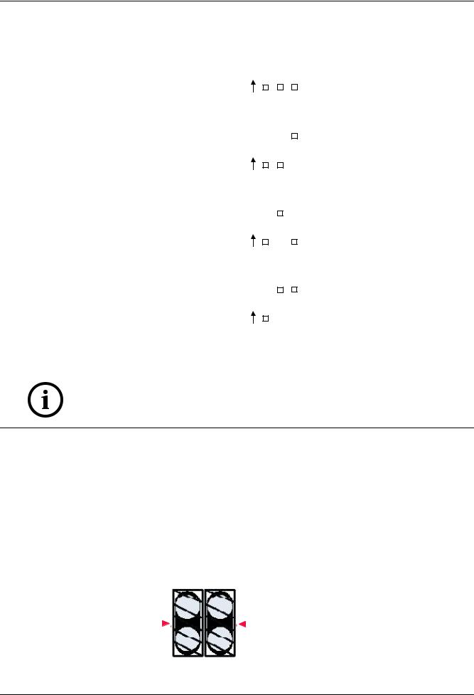
Access Easy Extension - Access Easy Extension is a metal enclosure identical in size to the basic AEC2.1. The Extension unit contains a Power Supply Unit, and space to install up to two additional 4-Reader boards and/or 8-IO boards. Space is provided for an optional 12V, 7AH standby battery to sustain the system in time of power failure.
NOTICE!
AEC2.1 does not come with the 12 VDC standby battery. Refer to Section 20 Appendix D Selecting A Correct Battery Size in this manual for backup battery specifications.
F.01U.122.796 | 1.0.5 | 2011.09 |
Hardware Manual |
Robert Bosch (SEA) Pte Ltd |
Access Easy Controller 2.1 System Layout | en 11
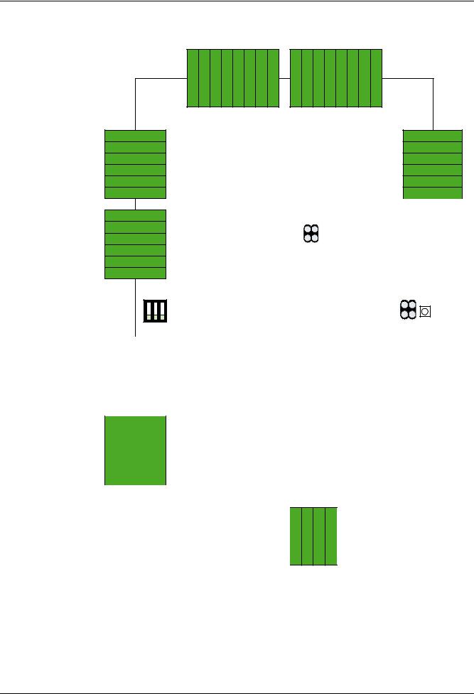
3 System Layout
Figure 3.1 System Layout
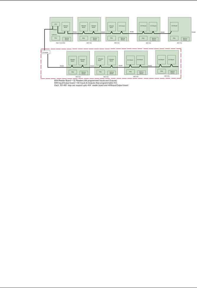
Each AEC2.1 system can support up to a maximum of 16 interface boards (eight 4-Reader boards and eight 8-IO boards). This configuration allows the system to support up to 32 Wiegand readers, 64 alarm type inputs and 64 controllable output points. System configurations may vary, based on the requirement of the customer.
Note: UL listed panic hardware shall be used for the applications.
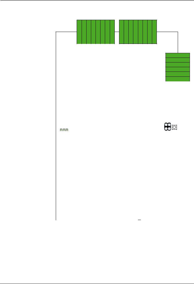
The figure below shows a basic configuration of the AEC2.1 system (including the converter and additional four 4-Reader boards and four 8-IO boards).
Figure 3.2 shows the basic configuration of AEC2.1 system with additional four 4 -Reader boards and four 8-IO boards using a converter. The converter UDS1100 can be linked to AEC2.1’s CPU LAN port through an ethernet network port to provide an additional multidrop communication channel upgrading it to support up to a maximum of 16 interface boards (eight 4-Reader boards and eight 8-IO boards). This allows the AEC2.1 system to support up to 32 card readers, 64 alarm type input and 64 controllable output points.
Robert Bosch (SEA) Pte Ltd |
Hardware Manual |
F.01U.122.796 | 1.0.5 | 2011.09 |
12 en | System Layout |
Access Easy Controller 2.1 |
|
|
Figure 3.2 Basic Configuration of AEC2.1 system
3.1 |
System Specifications |
|
|
|
|
Dimensions |
|
|
|
|
Enclosure (H x W x D) |
: 400mm x 400mm x 94mm |
|
|
|
Controller |
|
|
|
|
CPU |
: 32 bits Microprocessor 500 MHz or higher |
||
|
Memory |
: 128 MB RAM or higher |
|
|
|
Storage |
: Compact Flash 256 MB and above |
||
|
Data Integrity |
: Encryption used for user ID and PIN |
||
|
Power Requirements |
|
|
|
|
Primary Voltage Input (AC) |
: |
100~240 VAC |
|
|
Secondary Voltage Input |
: +5 VDC for CPU board |
|
|
|
|
|
+13.6 +/-0.1 VDC for 4-Reader and 8-IO boards |
|
|
Backup Battery |
: 12 VDC, 7 AH rechargable battery |
||
|
(Optional: Not included in standard package) |
|
||
|
Interface Boards |
: |
|
|
|
|
|
4-Reader Board |
8-IO Board |
|
Voltage Requirement |
: +13.6 +/-0.1 VDC from PSU |
+13.6 +/-0.1 VDC from PSU |
|
|
Number of Wiegand Readers |
: |
4 |
- |
|
Supported |
|
|
|
|
Number of Monitoring |
: |
8* |
8 |
|
Points |
|
|
|
|
Number of Output Control |
: |
8** |
8 |
|
Relays |
|
|
|
F.01U.122.796 | 1.0.5 | 2011.09 |
Hardware Manual |
Robert Bosch (SEA) Pte Ltd |

Access Easy Controller 2.1 |
System Layout | en 13 |
|
|
NOTICE!
* Input Monitoring Points on the 4-Reader board consist of door contact input and request-to- exit inputs associated with reader-controlled doors.
** Output Control Relays on the 4-Reader board are the door strike/magnetic lock control relays for the reader-controlled doors.
Readers Supported by AEC2.1 |
|
|
|
Standard Wiegand I/P |
: |
HID MiniProx Reader, HID ProxPoint Reader, HID ProxPro |
|
Reader |
|
with/without Keypad Reader, HID iCLASS with/without |
|
|
|
keypad Reader (R10, R30, R40) |
|
Ports |
|
|
|
LAN Ports |
: |
Two RJ45 |
|
Serial Ports |
: |
Two RS232 |
|
Extension Ports |
: |
One RS485 |
|
AEC2.1 Capacity |
|
|
|
Number of Concurrent |
: |
8 |
|
Logins |
|
|
|
User Licenses |
: |
Max. 25 user account (including “superuser”), using up to |
|
|
|
50 characters, alphanumeric, case sensitive user IDs and |
|
|
|
passwords |
|
Database Integrity |
: |
Encryption used for user IDs and PINs |
|
Number of Cards Supported |
: |
20,480 |
|
Number of Access Groups |
: |
254 |
|
Number of Time Schedules |
: |
255 |
|
Interval per Time Schedules |
: |
Four intervals per day, plus holidays support |
|
Recommended Web |
: |
Microsoft Internet Explorer version 7.0 or above |
|
Browser |
|
|
|
|
|
4-Reader board |
8-IO board |
Max. Number of Interface |
: |
8 |
8 |
Board Supported in a Full |
|
|
|
AEC2.1 Configuration |
|
|
|
Max. Number of Wiegand |
: |
32 |
- |
Reader Supported in a Full |
|
|
|
AEC2.1 Configuration |
|
|
|
Max. Input Supported in a |
: |
- |
64 (Both normally opened |
Full AEC2.1 Configuration |
|
|
and normally closed |
|
|
|
devices supported) |
Max. Output Supported in a |
: |
- |
64 (Form-C PCB mounted |
Full AEC2.1 Configuration |
|
|
output control relays, with |
|
|
|
Contact Rating: 1A @ 24 |
|
|
|
VDC) |
Environment Conditions
Robert Bosch (SEA) Pte Ltd |
Hardware Manual |
F.01U.122.796 | 1.0.5 | 2011.09 |

14 en | System Layout Access Easy Controller 2.1
Temperature (Operating) |
: |
0 to +50 deg.C (32 to 120 deg.F) |
Relative Humidity |
: |
10% to 85% (+/- 5%) at 32 d eg.C (+90 deg.F) |
Certifications and Approvals |
|
|
Certifications, Approvals, |
: |
CE, FCC |
and Safety Standards that |
|
|
AEC2.1 comply with |
|
|
F.01U.122.796 | 1.0.5 | 2011.09 |
Hardware Manual |
Robert Bosch (SEA) Pte Ltd |
Access Easy Controller 2.1 The CPU Board | en 15
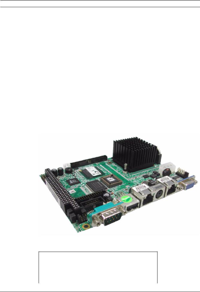
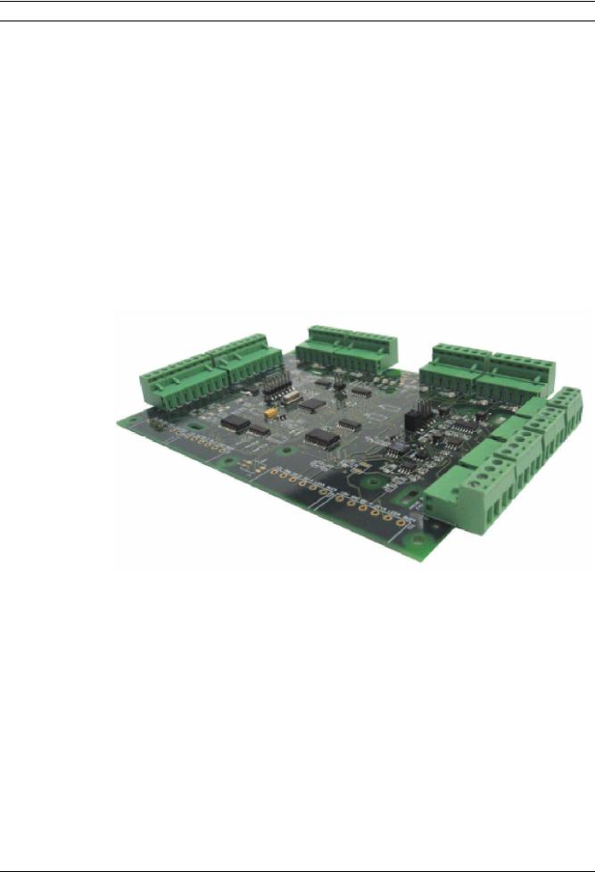
4 The CPU Board
This chapter provides a brief overview of the AEC2.1 CPU board. This chapter also describes the board layout and functions of various circuits. Some major components of the board are explained and information concerning jumper option is provided.
The AEC2.1 CPU board is X86 processor based Single Board Computer (SBC) with one or two 100Base-T Ethernet. The serial port (RS232), communicates with the 4-Reader and/or 8-IO boards.
The CPU board is designed to function as an embedded Web server and an AEC2.1 system.
Two communication ports are available on the CPU board. The first is an 100Base-T Ethernet port used by the Web server to communicate with the customer's database management computers. The Ethernet port terminates in an RJ-45 jack located on the CPU board. Standard category 5 cable is used to connect from the RJ-45 jack to a hub or wall outlet on the customer's network. Alternatively, a cross-over cable can be used to connect from the Ethernet jack on the CPU board directly to the Ethernet connector on the customer's computer.
The second communication port is a RS-232 port. This port is used to connect to an external modem to allow dial-in connection to the controller.
Figure 4.1 CPU Board
Specification for CPU
Input Voltage |
+5 VDC (4.75 VDC to 5.25 VDC) |
|
|
Current Consumption |
1.95 A @ 5 VDC |
|
|
CPU speed |
500 MHz |
|
|
RAM |
512 MB |
|
|
Robert Bosch (SEA) Pte Ltd |
Hardware Manual |
F.01U.122.796 | 1.0.5 | 2011.09 |

16 en | The CPU Board Access Easy Controller 2.1
4.1 Component Layout of the CPU Board
The following layout diagrams shows the major physical components on the CPU board. A brief description is provided on some of the major components.
There are three different types of CPU boards, hence the layout of each type will be slightly different. The diagrams below shows each type and the location of the relevant components.
Figure 4.2 Type1 CPU Board
Figure 4.3 Type2 CPU Board
F.01U.122.796 | 1.0.5 | 2011.09 |
Hardware Manual |
Robert Bosch (SEA) Pte Ltd |

Access Easy Controller 2.1 |
The CPU Board | en 17 |
|
|
Figure 4.4 Type3 CPU Board
Ethernet Connector
A Category 5 cable is connected from this RJ45 socket to the plug-in 100BaseT Ethernet card located in the Central Monitoring Computer directly or via a hub. The table below shows the pin configuration for the socket.
100Base-Tx Ethernet connector
1 |
Tx+ |
2 |
Tx- |
|
|
|
|
3 |
Rx+ |
4 |
NC |
|
|
|
|
5 |
NC |
6 |
Rx- |
|
|
|
|
7 |
NC |
8 |
NC |
|
|
|
|
Serial Port for Modem
This is a standard RS232 communication port used for modem connection. Refer to cable connection for more details.
Serial Port for the interface board
This is a 9 pins serial port. The serial port is connected to the interface boards.
RS232 Serial Port
Pin |
Signal |
Pin |
Signal |
|
|
|
|
1 |
DCDB |
2 |
RXDB |
|
|
|
|
3 |
TXDB |
4 |
DTRB |
|
|
|
|
5 |
GND |
6 |
DSRB |
|
|
|
|
7 |
RTSB |
8 |
CTSB |
|
|
|
|
9 |
RIB |
10 |
- |
|
|
|
|
Robert Bosch (SEA) Pte Ltd |
Hardware Manual |
F.01U.122.796 | 1.0.5 | 2011.09 |

18 en | The CPU Board |
Access Easy Controller 2.1 |
|
|
5 VDC & 12 VDC Power Input
The CPU board can be powered up by the 100~240 VAC input PSU.
Refer to Section 7 Power Supply Unit for further information before connecting any power source to the CPU board.
|
|
Power Connector |
|
|
|
|
|
|
|
Pin |
Signal |
|
|
|
|
|
|
1 |
+5V |
|
|
|
|
|
|
2 |
GND |
|
|
|
|
|
|
3 |
GND |
|
|
|
|
|
|
4 |
+12Vcc |
|
|
|
|
4.1.1 |
Other Components |
|
|
Lithium Battery Holder
This is the location where a 3V Lithium battery is situated. The Lithium battery provides continuous power supply to the Real Time Clock circuitry in case of a power outage. The power will only be drawn from this battery under the following conditions: -
–No power is supplied from the PSU, and
–The external 12V rechargeable battery is not charged sufficiently, or is drained for prolong period of time and unable to provide backup power.
NOTICE!
It is recommended that this battery be changed every 2 years. Recommended replacements are the Panasonic Model CR2032 Lithium Battery for Axiom and A-Value CPU boards, or the Varta Model CR2032 Lithium Battery.
CAUTION!
Batteries should only be replaced by a qualified service technician.
F.01U.122.796 | 1.0.5 | 2011.09 |
Hardware Manual |
Robert Bosch (SEA) Pte Ltd |
Access Easy Controller 2.1 4-Reader Board | en 19
5 |
4-Reader Board |
|
This chapter describes one of the interface boards used by the AEC2.1 system. This section |
|
identifies and locates key components on the board and includes a brief overview of the |
|
functional operation. |
|
The first is the 4-Reader board, which provides all the termination points needed to fully |
|
manage four card readers and all associated supporting hardware. The board size and |
|
location of mounting holes on both the 4-Reader board and 8-IO board are the same. |
5.1 |
Technical Overview of 4-Reader Board |
|
Figure 5.1 4-Reader Board |
5.1.1 |
Component Layout of 4-Reader Board |
|
The diagram below shows the layout and major components of the 4-Reader board. A brief |
|
technical description of the components is provided in the following pages. |
Robert Bosch (SEA) Pte Ltd |
Hardware Manual |
F.01U.122.796 | 1.0.5 | 2011.09 |
20 en | 4-Reader Board |
Access Easy Controller 2.1 |
|
|
BOSCH
T7
Gnd
T8 12V
Gnd
DO-1
D1-1
LED1
BUZ1
T9 12V
Gnd
DO-2
D1-2
LED2
BUZ2
1 2 3
SW1
In8 |
Gnd |
In7 |
Gnd |
|
|
|
T6 |
|
|
|
|
|
|
|
In6 |
Gnd |
In5 |
Gnd |
In4 |
Gnd |
In3 |
Gnd |
In2 |
Gnd |
In1 |
COM1 T2
LED1 
 NC1
NC1
NO1
COM2
LED2 
 NC2
NC2
NO2
|
|
|
|
|
|
|
|
|
JP2 |
|
|
COM3 |
T3 |
|
|||
|
LED3 |
|
NC3 |
|
|
|
|
|
|
|
|
|
|
|
|||
|
|
|
|
|
|
|||
|
|
|
|
NO3 |
|
|
|
|
|
|
|
COM4 |
|
|
|
|
|
|
LED4 |
|
NC4 |
|
|
|
|
|
|
|
|
|
|
|
|||
|
|
|
|
NO4 |
|
|
|
|
|
LED9 |
|
|
RUN |
JP1 |
|
||
|
|
|
SW2 |
|
||||
4-Reader Board |
LED10 |
|
|
TX |
|
|||
|
|
|
|
|
|
|||
|
|
|
|
|
|
|||
|
LED11 |
|
|
RX |
|
|
|
|
|
|
|
|
|
|
|
||
|
|
|
|
|
|
|
||
|
LED12 |
|
|
CARD READ |
|
|||
|
|
|
|
|||||
|
|
|
|
|||||
|
|
|
|
|
|
|
|
|
|
T10 |
12V |
|
|
Gnd |
|
|
DO-3 |
|
|
D1-3 |
|
|
LED3 |
|
|
BUZ3 |
|
|
|
|
T11 |
12V |
|
|
Gnd |
|
|
|
|
|
DO-4 |
|
|
|
|
|
D1-4 |
|
|
|
|
|
LED4 |
|
|
|
|
|
BUZ4 Main |
|
|
|
|
|
+ - |
+ - |
|
Earth |
B A |
Shield |
|
|||
|
|
|
PWR |
Tamper |
|
RS485 |
|
|
||||
|
|
|
Fail |
|
|
|
||||||
|
|
|
|
|
|
|
|
|||||
|
|
|
|
|
|
|
|
|
|
|
|
|
|
|
|
|
|
|
T12 |
|
|
|
|
T13 |
|
|
|
|
|
|
|
|
|
|
|
|
|
|
|
|
|
|
|
|
|
|
|
|
|
|
|
Figure 5.2 4-Reader Board Layout
RTS
RS232 TX RX
GND
T14
|
|
|
|
|
COM5 |
T4 |
|
||
|
LED5 |
|
|
|
NC5 |
|
|
||
|
|
|
|
|
|
||||
|
|
|
|
|
|
||||
|
|
|
|
|
|
NO5 |
|
|
|
|
|
|
|
|
COM6 |
|
|
||
|
LED6 |
|
|
|
NC6 |
|
|
||
|
|
|
|
|
|
||||
|
|
|
|
|
|
||||
|
|
|
|
|
|
NO6 |
|
|
|
|
|
|
|
|
|
|
|
|
|
|
|
|
|
|
COM7 |
T5 |
|
||
|
LED7 |
|
|
|
NC7 |
|
|
||
|
|
|
|
|
|
||||
|
|
|
|
|
|
NO7 |
|
|
|
|
|
|
|
|
COM8 |
|
|
||
|
LED8 |
|
|
|
NC8 |
|
|
||
|
|
|
|
|
|
||||
|
|
|
|
|
|
NO8 |
|
|
|
DC 15V DC 15V |
|
|
|||||||
|
IN |
|
OUT |
|
|
||||
+ - |
+ - |
|
|
|
|
||||
|
|
|
|
|
T1 |
|
|
|
|
|
|
|
|
|
|
|
|
|
|
|
|
|
|
|
|
|
|
|
|
5.1.2 Reader Connectors
The Reader board contains four 6-pin terminal strips down the left side of the board. Each terminal strip provides wiring terminations for one standard Wiegand output reader. The terminal strips are labelled on the board as T8, T9, T10 and T11. T8 provides the termination points for reader 1, T9 for reader 2, T10 for reader 3, and T11 for reader 4.
F.01U.122.796 | 1.0.5 | 2011.09 |
Hardware Manual |
Robert Bosch (SEA) Pte Ltd |
Access Easy Controller 2.1 |
4-Reader Board | en 21 |
|
|
The pin configured for each reader connector is shown in the table below.
Pin# |
Function |
|
|
1 |
12 VDC |
|
|
2 |
Ground |
|
|
3 |
Data 0 |
|
|
4 |
Data 1 |
|
|
5 |
Green LED Control |
|
|
6 |
Buzz Control |
|
|
NOTICE!
Each connector is able to provide a maximum current of 150mA at 12 VDC. This is sufficient power for most readers. Readers requiring higher current will need to have the power supplied from an external power supply.
5.1.3 |
Input Connectors |
|
|
|
|
|
Two 8-pin terminal strips across the top of the 4-Reader board provide termination points for |
||
|
|
the door contacts and request-to-exit devices associated with the readers. The terminal strips |
||
|
|
are identified as T6 and T7 on the 4-Reader board. |
||
|
|
For each of the four readers this board can control, there are two terminals each for |
||
|
|
connection of a door contact and a request-to-exit device. Both circuits (contact and REX) are |
||
|
|
supervised and should be terminated according to the type of supervision applied to that |
||
|
|
particular input (Section 9.5.1 Wiring Diagram for Supervised Inputs, page 51). If either contact |
||
|
|
or REX device are not to be used, then the termination resistor should be installed across the |
||
|
|
terminals within the controller. Refer to Section 9 How to Install Reader and Field Devices, |
||
|
|
page 41, for detailed wiring diagrams. |
||
|
|
The tables below show the various termination points on the terminal strips. |
||
|
|
|
|
|
|
|
T6 Terminal Strip |
|
|
|
|
|
|
|
|
|
IN1 |
Request-to-exit for reader #1 |
|
|
|
|
|
|
|
|
GND |
Request-to-exit for reader #1 |
|
|
|
|
|
|
|
|
IN2 |
Door contact for reader #1 |
|
|
|
|
|
|
|
|
GND |
Door contact for reader #1 |
|
|
|
|
|
|
|
|
IN3 |
Request-to-exit for reader #2 |
|
|
|
|
|
|
|
|
GND |
Request-to-exit for reader #2 |
|
|
|
|
|
|
|
|
IN4 |
Door contact for reader #2 |
|
|
|
|
|
|
|
|
GND |
Door contact for reader #2 |
|
|
|
|
|
|
|
|
|
|
|
|
|
T7 Terminal Strip |
|
|
|
|
|
|
|
|
|
IN5 |
Request-to-exit for reader #3 |
|
|
|
|
|
|
|
|
GND |
Request-to-exit for reader #3 |
|
|
|
|
|
|
|
|
IN6 |
Door contact for reader #3 |
|
|
|
|
|
|
|
|
GND |
Door contact for reader #3 |
|
|
|
|
|
|
|
|
IN7 |
Request-to-exit for reader #4 |
|
|
|
|
|
|
|
|
GND |
Request-to-exit for reader #4 |
|
|
|
|
|
|
Robert Bosch (SEA) Pte Ltd |
Hardware Manual |
F.01U.122.796 | 1.0.5 | 2011.09 |

22 en | 4-Reader Board Access Easy Controller 2.1
T7 Terminal Strip |
|
|
|
IN8 |
Door contact for reader #4 |
|
|
GND |
Door contact for reader #4 |
|
|
5.1.4 Output Connectors
Four 6-pin terminal strips provide connections for door strike and/or magnetic lock control. The four terminal strips are labelled on the circuit boards as T2, T3, T4 and T5. The output terminals are Form-C type dry contacts from relays located on the 4-Reader board. Each output relay provides Normally Closed (N/C), Normally Open (N/O) and a Common terminal (COM). Each relay also has a corresponding LED, that lights up whenever the relay is activated.
T2 provides output connection points for readers 1 and 2. T3 provides output connection points for readers 3 and 4. T4 provides connection points for two spare relays. T5 provides two spare relay outputs, except on the first 4-Reader board. T5, relay 8 provides a common alarm output for all Reader boards.
On the first 4-Reader board, the last relay is assigned in the software to provide a common alarm output from the controller. This relay is intended to provide an easy hand-off by the controller of an alarm indication to an external burglar alarm system. The common alarm relay will activate whenever a Door Forced Open or Door Held Open alarm is detected by the controller. It will also activate when the controller's door tamper circuit is activated, or in occurrence of an AC power failure.
The common alarm relay will reset when all alarm conditions have returned to normal.
Detailed information concerning the common alarm output is provided in this manual.
NOTICE!
The contacts of all relays are rated at DC 24V/1A maximum.
The pin configuration for each output connectors is shown in the tables below.
T2 Terminal Strip (top terminal)
Pin# |
Function |
|
|
1 |
Reader #1 (common) |
|
|
2 |
Reader #1 (Normally closed) |
|
|
3 |
Reader #1 (normally open) |
|
|
4 |
Reader #2 (common) |
|
|
5 |
Reader #2 (normally closed) |
|
|
6 |
Reader #2 (normally open) |
|
|
T3 Terminal Strip (second terminal from top)
Pin# |
Function |
|
|
1 |
Reader #3 (common) |
|
|
2 |
Reader #3 (Normally closed) |
|
|
3 |
Reader #3 (normally open) |
|
|
4 |
Reader #4 (common) |
|
|
F.01U.122.796 | 1.0.5 | 2011.09 |
Hardware Manual |
Robert Bosch (SEA) Pte Ltd |
Access Easy Controller 2.1 |
4-Reader Board | en 23 |
|
|
T3 Terminal Strip (second terminal from top)
Pin# |
Function |
|
|
5 |
Reader #4 (normally closed) |
|
|
6 |
Reader #4 (normally open) |
|
|
T4 Terminal Strip (third terminal from top)
Pin# |
Function |
|
|
1 |
Spare (common) |
|
|
2 |
Spare (Normally closed) |
|
|
3 |
Spare (normally open) |
|
|
4 |
Spare (common) |
|
|
5 |
Spare (normally closed) |
|
|
6 |
Spare (normally open) |
|
|
|
|
T5 Terminal Strip (bottom terminal) |
|
|
|
Pin# |
Function |
|
|
1 |
Spare (common) |
|
|
2 |
Spare (Normally closed) |
|
|
3 |
Spare (normally open) |
|
|
4 |
Common Alarm Output (common) |
|
|
5 |
Common Alarm Output (normally closed) |
|
|
6 |
Common Alarm Output (normally open) |
|
|
NOTICE!
The common alarm output relay only exists on the first 4-Reader board. On boards 2, 3 and 4 this relay is an additional spare.
5.1.5 |
15 VDC Input Termination |
Reference: Terminal Strip T1
Terminal strip T1 is used to provide up to 15 VDC power to the interface boards (e.g. 4-Reader board and 8-IO board). It consists of four terminals. Two terminals provide the input power for the board (DC 15V IN), and the next two terminals provide the input power for the next board (DC 15V OUT), within the same casing. The diagram below shows the configuration of the terminal strip T1. It receives 13 VDC from the PSU.
DC 15V DC 15V
IN |
OUT |
||
+ - |
+ - |
||
|
|
|
T1 |
|
|
|
|
Figure 5.3 15 VDC Input Terminal
Robert Bosch (SEA) Pte Ltd |
Hardware Manual |
F.01U.122.796 | 1.0.5 | 2011.09 |
24 en | 4-Reader Board Access Easy Controller 2.1
5.1.6 RS232
Reference: Terminal Strip T14
Terminal strip T14 is used as a communication channel between the interface board (e.g. 4- Reader board and 8-IO board) and the CPU. The channel consists of four data cables, namely RTS, TX, RX, and Gnd. The cables are connected to the serial COM port on the CPU. The diagram below shows the configuration of the terminal strip T14.
RTS
RS232 TX RX
GND
T14
|
Figure 5.4 RS232 |
5.1.7 |
RS485 |
|
Reference: Terminal Strip T13 |
|
Terminal strip T13 is used as a communication channel between the interface boards (e.g. 4- |
|
Reader board and 8-IO board). RS485 is a multi-drop communication channel. It enables the |
|
CPU to disseminate and receive data to and from all the interface boards. It consists of four |
24-AWG-CAT5 cables, namely EARTH, B, A and SHIELD. All the interface boards within the system are connected using the RS485 terminal. The diagram below shows the connections on the terminal strip T13.
EARTH
RS485
BA
SHIELD
T13
|
Figure 5.5 RS485 |
5.1.8 |
Tamper and Main Power Fail |
|
Reference: Terminal Strip T12 |
|
Terminal strip T12 comprises of Tamper alarm and Main Power Fail alarm inputs. The Tamper |
terminals are connected to a micro-switch that is used to monitor the enclosure’s cover against unauthorized tampering. Any opening of the enclosure cover will trigger the Common Alarm output and sounds off the CPU buzzer. A Controller Tamper alarm message is sent to the Transactions page of the AEC2.1 user software.
The Main Power Fail alarm will be triggered when the input AC power is cut off and the backup battery takes over. The terminals will be shorted together.
PWR |
TAMPER |
||
FAIL |
|||
+ - |
+ - |
||
|
|
|
T12 |
|
|
|
|
Figure 5.6 Tamper and Main Power Fail
F.01U.122.796 | 1.0.5 | 2011.09 |
Hardware Manual |
Robert Bosch (SEA) Pte Ltd |
Access Easy Controller 2.1 4-Reader Board | en 25
5.1.9 |
LED Indicators |
|
Reference: LED 1 to LED 8 |
|
LEDs 1 to 8 light whenever the associated relay is activated. |
|
Reference: LED9 |
|
This LED indicates that the processor on the 4-Reader board is running. |
|
Reference: LED 10 and LED 11 |
|
These LEDs should blink in normal operation. This indicates normal communication between |
|
the 4-Reader board and the CPU board. |
|
Reference: LED 12 |
|
This LED will blink once each time card is presented to a reader. |
5.1.10 |
Reset Button |
|
Reference: SW2 |
|
SW2 is a reset button to reset the processor on the interface board. |
5.1.11 |
End-of-Line Setting |
|
Reference: JP1 |
|
AEC2.1 uses RS485 multi-drop communication channels between the CPU and interface |
|
boards. It is necessary to include the end-of-line jumper settings on the last interface board in |
|
configuration to have a stable communication channel. |
Jumper
Link
JP1
|
Figure 5.7 Jumper Setting |
5.1.12 |
Address Setting Switch |
|
Reference: SW1 |
SW1 is switch to set the address of individual interface boards. It consists of two dip switches for setting of the address in binary sequence. Each AEC2.1 can manage up to eight 4-Reader boards and eight 8-IO boards. The address settings for the 4-Reader boards are shown in the table below.
Robert Bosch (SEA) Pte Ltd |
Hardware Manual |
F.01U.122.796 | 1.0.5 | 2011.09 |
26 en | 4-Reader Board |
Access Easy Controller 2.1 |
|
|
|
|
|
|
|
|
|
|
|
|
|
|
|
|
|
|
|
|
|
|
Address setting using SW1 for the |
|
ON |
|
|
|
|
|
|
|
|
|
|
|
|
|
The 1st 4-Reader board will |
|
|
|
|
|
|
|
|
|
|
|
|
|
|
|
|
|
|||
|
|
|
|
|
|
|
|
|
|
|
|
|
|
|
|
|
||
|
1st and 5th 4-Reader board in |
|
|
|
|
|
|
|
|
|
|
|
|
|
|
|
consist of readers 1 to 4 |
|
|
AEC2.1 system. |
|
|
|
|
|
|
|
|
|
|
|
|
|
|
|
|
|
|
|
|
|
|
|
|
|
|
|
|
|
|
|
|
|
|
|
|
|
|
|
|
|
|
|
|
|
|
|
|
|
|
|
|
|
|
|
|
|
|
1 |
|
2 |
|
3 |
|
|
|
The 5th 4-Reader board will |
|
||||||
|
|
|
|
|
|
|
|
|
|
|
|
|
|
|
|
|
|
|
|
|
|
|
|
|
|
|
|
|
|
|
|
|
|
|
|
consist of readers 17 to 20 |
|
|
|
|
|
|
|
|
|
|
|
|
|
|
|
|
|
|
|
|
|
|
|
ON |
|
|
|
|
|
|
|
|
|
|
|
|
|
|
|
|
Address setting using SW1 for the |
|
|
|
|
|
|
|
|
|
|
|
|
|
|
The 2nd 4-Reader board will |
|
|
|
|
|
|
|
|
|
|
|
|
|
|
|
|
|
|
|
||
|
2nd and 6th 4-Reader board in |
|
|
|
|
|
|
|
|
|
|
|
|
|
|
|
consist of readers 5 to 8 |
|
|
|
|
|
|
|
|
|
|
|
|
|
|
|
|
|
|
||
|
|
|
|
|
|
|
|
|
|
|
|
|
|
|
|
|
||
|
|
1 |
|
2 |
|
3 |
|
|
|
|
||||||||
|
AEC2.1 system. |
|
|
|
|
|
|
The 6th 4-Reader board will |
|
|||||||||
|
|
|
|
|
|
|
|
|
|
|
|
|
|
|
|
|
||
|
|
|
|
|
|
|
|
|
|
|
|
|
|
|
|
|
consist of readers 21 to 24 |
|
|
|
|
|
|
|
|
|
|
|
|
|
|
|
|
|
|
|
|
|
|
|
ON |
|
|
|
|
|
|
|
|
|
|
|
|
|
|
|
|
Address setting using SW1 for the |
|
|
|
|
|
|
|
|
|
|
|
|
|
|
The 3rd 4-Reader board will |
|
|
|
|
|
|
|
|
|
|
|
|
|
|
|
|
|
|
|
||
|
3rd and 7th 4-Reader board in |
|
|
|
|
|
|
|
|
|
|
|
|
|
|
|
consist of readers 9 to 12 |
|
|
|
|
|
|
|
|
|
|
|
|
|
|
|
|
|
|
||
|
|
1 |
|
2 |
|
3 |
|
|
|
|
||||||||
|
AEC2.1 system. |
|
|
|
|
|
|
The 7th 4-Reader board will |
|
|||||||||
|
|
|
|
|
|
|
|
|
|
|
|
|
|
|
|
|
||
|
|
|
|
|
|
|
|
|
|
|
|
|
|
|
|
|
consist of readers 25 to 28 |
|
|
|
|
|
|
|
|
|
|
|
|
|
|
|
|
|
|
|
|
|
|
|
ON |
|
|
|
|
|
|
|
|
|
|
|
|
|
|
|
|
Address setting using SW1 for the |
|
|
|
|
|
|
|
|
|
|
|
|
|
|
The 4th 4-Reader board will |
|
|
|
|
|
|
|
|
|
|
|
|
|
|
|
|
|
|
|
||
|
4th and 8th 4-Reader board in |
|
|
|
|
|
|
|
|
|
|
|
|
|
|
|
consist of readers 13 to 16 |
|
|
|
|
|
|
|
|
|
|
|
|
|
|
|
|
|
|
||
|
|
1 |
|
2 |
|
3 |
|
|
|
|
||||||||
|
AEC2.1 system. |
|
|
|
|
|
|
The 8th 4-Reader board will |
|
|||||||||
|
|
|
|
|
|
|
|
|
|
|
|
|
|
|
|
|
||
|
|
|
|
|
|
|
|
|
|
|
|
|
|
|
|
|
consist of readers 29 to 32 |
|
|
|
|
|
|
|
|
|
|
|
|
|
|
|
|
|
|
|
|
|
|
|
|
|
|
|
|
|
|
|
|
|
|
|
|
|
|
|
NOTICE!
The boards are addressed in binary sequence. AEC2.1 can support up to 16 interface boards, eight 4-Reader boards and eight 8-IO boards. The address pin ‘1’ is reserved for future development, to expand the capability of AEC2.1.
5.1.13 |
Factory Default Setting |
Reference: JP2
JP2 of the first 4-Reader board is used to reset the AEC2.1 back to factory default. JP2 carries two functions:
–Clearing all information, settings and configuration. (IP address will not be reset with this function)
–Resetting the IP address of the panel back to default IP
Refer to Section 24 Appendix H Resetting to Factory Default, page 118 for detail instructions.
|
|
|
JP2 |
||
Jumper Link to reset |
Jumper Link to |
||||
to factory default |
reset IP address |
||||
|
|
|
|
|
|
Figure 5.8 Factory Default Setting
F.01U.122.796 | 1.0.5 | 2011.09 |
Hardware Manual |
Robert Bosch (SEA) Pte Ltd |

Access Easy Controller 2.1 |
4-Reader Board | en 27 |
|
|
CAUTION!
–Resetting the system to factory default settings will clear the data stored in the AEC2.1 system. Be sure to do a backup of the system before resetting.
–After rebooting the system, remove the jumper links from the 4-Reader board.
–This function is only available to the first 4-Reader board of the AEC2.1 configuration, although all the 4-Reader board comes with JP2.
Robert Bosch (SEA) Pte Ltd |
Hardware Manual |
F.01U.122.796 | 1.0.5 | 2011.09 |
28 en | 8-Input-Output Board Access Easy Controller 2.1
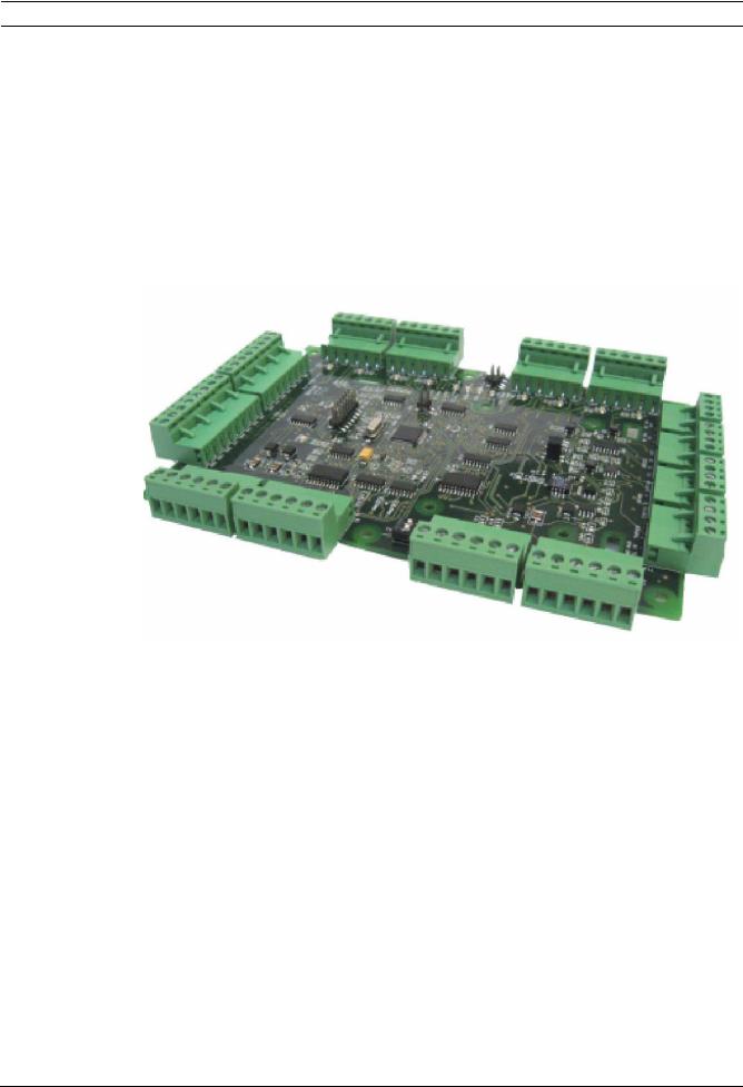
6 |
8-Input-Output Board |
|
This chapter describes one of the interface boards employed by the AEC2.1. This section |
|
identifies and locates key components on the board and includes a brief overview of the |
|
functional operation. |
|
The 8-IO board provides eight zones of end-of-line resistor type inputs and eight contact |
|
closure outputs. This board is intended for non-reader type applications where it is desirable |
|
to monitor emergency exit doors, or motion detectors. This board also provides eight Form-C |
|
type relay outputs, which can be used to control external equipment, such as lights, gate |
|
motor, etc. |
|
The board size and location of mounting holes on both the 4-Reader board and 8-IO board are |
|
the same. |
6.1 |
Technical Overview of 8-Input-Output Board |
|
Figure 6.1 8-Input-Output Board |
6.1.1 |
Component Layout of 8-Input-Output Board |
|
The diagram below shows the layout of 8-IO board. All major components are identified on the |
|
diagram, and a brief technical description is provided in the following pages. |
F.01U.122.796 | 1.0.5 | 2011.09 |
Hardware Manual |
Robert Bosch (SEA) Pte Ltd |
Access Easy Controller 2.1 |
8-Input-Output Board | en 29 |
|
|
BOSCH
T7 |
|
|
|
|
|
|
|
T6 |
|
|
|
Gnd |
In8 |
Gnd |
In7 |
Gnd |
In6 |
Gnd |
In5 |
Gnd |
In4 |
Gnd |
In3 |
1 2 3
|
|
|
|
|
|
SW1 |
8 Input Output Board |
|
|
|
|
|
|
|
|
|
Main |
+ - |
|
Earth |
B A |
Shield |
|
RTS |
TX RX |
GND |
||||
|
+ - |
|
|
|||||||||||
|
PWR |
Tamper |
|
RS485 |
|
|
|
RS232 |
|
|||||
|
Fail |
|
|
|
|
|
||||||||
|
|
|
|
|
|
|
|
|
|
|||||
|
|
|
|
|
|
|
|
|
|
|
|
|
|
|
|
|
|
|
T12 |
|
|
|
|
T13 |
|
|
|
|
T14 |
|
|
|
|
|
|
|
|
|
|
|
|
|
|
|
|
|
|
|
|
|
|
|
|
|
|
|
|
|
|
Figure 6.2 Layout of 8-Input-Output Board
Gnd |
In2 |
Gnd |
In1 |
COM1 T2
LED1 
 NC1
NC1
NO1
COM2
LED2 
 NC2
NC2
NO2
|
|
|
|
|
|
|
|
|
|
|
|
|
|
|
COM3 |
T3 |
|
||||
LED3 |
|
|
|
NC3 |
|
|
|
|
||
|
|
|
|
|
|
|
||||
|
|
|
|
|
|
|
||||
|
|
|
|
|
NO3 |
|
|
|
|
|
|
|
|
|
COM4 |
|
|
|
|
||
LED4 |
|
|
|
NC4 |
|
|
|
|
||
|
|
|
|
|
|
|
||||
|
|
|
|
|
|
|
||||
|
|
|
|
|
NO4 |
|
|
|
|
|
|
|
|
|
|
|
|
|
|
|
|
LED9 |
|
|
|
RUN |
JP1 |
|
||||
|
|
|
SW2 |
|
||||||
|
|
|
|
|||||||
LED10 |
|
|
|
TX |
|
|||||
|
|
|
|
|
|
|
||||
|
|
|
|
|
|
|
||||
LED11 |
|
|
|
RX |
|
|
|
|
||
|
|
|
|
|
|
|
||||
|
|
|
|
|
|
|
||||
LED12 |
|
|
|
CARD READ |
|
|||||
|
|
|
|
|||||||
|
|
|
|
|||||||
|
|
|
|
|
|
|
|
|
|
|
|
|
|
|
COM5 |
T4 |
|
||||
LED5 |
|
|
|
NC5 |
|
|
|
|
||
|
|
|
|
|
|
|
||||
|
|
|
|
|
|
|
||||
|
|
|
|
|
NO5 |
|
|
|
|
|
|
|
|
|
COM6 |
|
|
|
|
||
LED6 |
|
|
|
NC6 |
|
|
|
|
||
|
|
|
|
|
|
|
||||
|
|
|
|
|
|
|
||||
|
|
|
|
|
NO6 |
|
|
|
|
|
|
|
|
|
|
|
|
|
|
|
|
|
|
|
|
COM7 |
T5 |
|
||||
LED7 |
|
|
|
NC7 |
|
|
|
|
||
|
|
|
|
|
|
|
||||
|
|
|
|
|
|
|
||||
|
|
|
|
|
NO7 |
|
|
|
|
|
|
|
|
|
COM8 |
|
|
|
|
||
LED8 |
|
|
|
NC8 |
|
|
|
|
||
|
|
|
|
|
|
|
||||
|
|
|
|
|
NO8 |
|
|
|
|
|
DC 15V DC 15V |
|
|
|
|
||||||
IN |
|
OUT |
|
|
|
|
||||
+ - |
+ - |
|
|
|
|
|
|
|||
|
|
|
|
T1 |
|
|
|
|
|
|
|
|
|
|
|
|
|
|
|
|
|
|
|
|
|
|
|
|
|
|
|
|
6.1.2 Input Connectors
Two 8-pin terminal strips across the top of the 8-IO board provide termination points for wiring from door contacts and other alarm sensors. The terminal strips are identified as T6 and T7 on the 8-IO board.
Robert Bosch (SEA) Pte Ltd |
Hardware Manual |
F.01U.122.796 | 1.0.5 | 2011.09 |

30 en | 8-Input-Output Board Access Easy Controller 2.1
There are two terminals for each input point. Each input point is supervised and must be terminated according to the type of supervision applied to that particular input (Refer to
Section 9.5.1 Wiring Diagram for Supervised Inputs, page 51). All unused points should have the termination resistor installed across the terminals within the controller. Refer to Section 5 4- Reader Board, page 19 for detailed wiring diagrams.
|
|
The charts below show the various termination points on the terminal strips. |
||
|
|
|
|
|
|
|
T6 Terminal Strip |
|
|
|
|
|
|
|
|
|
IN1 |
Input Point #1 |
|
|
|
|
|
|
|
|
GND |
Input Point #1 |
|
|
|
|
|
|
|
|
IN2 |
Input Point #2 |
|
|
|
|
|
|
|
|
GND |
Input Point #2 |
|
|
|
|
|
|
|
|
IN3 |
Input Point #3 |
|
|
|
|
|
|
|
|
GND |
Input Point #3 |
|
|
|
|
|
|
|
|
IN4 |
Input Point #4 |
|
|
|
|
|
|
|
|
GND |
Input Point #4 |
|
|
|
|
|
|
|
|
|
|
|
|
|
T7 Terminal Strip |
|
|
|
|
|
|
|
|
|
IN5 |
Input Point #5 |
|
|
|
|
|
|
|
|
GND |
Input Point #5 |
|
|
|
|
|
|
|
|
IN6 |
Input Point #6 |
|
|
|
|
|
|
|
|
GND |
Input Point #6 |
|
|
|
|
|
|
|
|
IN7 |
Input Point #7 |
|
|
|
|
|
|
|
|
GND |
Input Point #7 |
|
|
|
|
|
|
|
|
IN8 |
Input Point #8 |
|
|
|
|
|
|
|
|
GND |
Input Point #8 |
|
|
|
|
|
|
6.1.3 |
Output Connectors |
|
|
|
Four 6-pin terminal strips provide connection points for connection of external devices controlled by the AEC2.1. The terminal strips are labelled on the circuit board as T2, T3, T4 and T5. The output terminals are Form-C type dry contacts from relays located on the 8-IO board. For each relay, Normally Closed (N/C), Normally Open (N/O) and a Common terminal (COM) are provided.
NOTICE!
The contacts of all relays are rated at DC 24V/1A maximum
The relay contacts can be connected directly to many low voltages DC powered devices, including alarm bells, security lights, horns, etc. When using the outputs to control high voltage devices, such as lighting circuits, electric door controllers, gate motors, etc., an external interface relay must always be used. Also, use an external relay when interfacing with AC-power devices.
In all instances where the output relay is used to operate an inductive load, such as when interfacing with an external relay, or powering the coil of an alarm bell, a back-biased diode
F.01U.122.796 | 1.0.5 | 2011.09 |
Hardware Manual |
Robert Bosch (SEA) Pte Ltd |
Loading...